Waste Incineration
Early Fire Detection and Automatic Extinguishing in Waste-to-Energy Power Plants and Waste Treatment Plants
Albert Orglmeister
1. Fire protection challenges – current status quo ...261
1.1. Why are there so many major fire incidents despite existing fire protection measures? ...261
1.2. What are the main causes of these major fires?...263
1.3. Industry applications – or: Which fire detection options are available for waste-to-energy plants and recycling companies? ...264
2. Infrared detection and thermal imaging technology with automatic extinguishing ...266
2.1. Short introduction to thermal imaging ...266
2.2. Past problems ...268
2.3. State-of-the-art technology ...268
2.4. Infrared early fire detection ...269
2.5. Automatic extinguishing ...270
2.6. Application examples ...271
2.7. Summary and outlook ...273
1. Fire protection challenges – current status quo 1.1. Why are there so many major fire incidents despite
existing fire protection measures?
In the UK, for example, according to a recent Resource Magazine online article, the waste industry has an average of one fire a day.
The UK Government revealed that in the years 2001 to 2012 the average rate of fires at waste and recycling works came in at ‘just under’ one per day (335 fires per year).
Naturally, these statistics vary from country to country, and as can be seen from the International Technical Committee for the Prevention and Extinction of Fire CTIF table below as a sample, some other countries face even more fire incidents in the waste sector.
Waste Incineration Table 1: Fire statistics by types Distribution of fires by types in the countries of the World in 2015 Number of fires No. CountryStructure fires%Vehicles%Forests%Grass, brush%Rubbish%Other% 1 Austria19,12377.71,5846.48833.62,74411.1– – 2881.2 2 Belarus5,31872.54586.21,21816.6– – – – 3454.7 3 Bulgaria3,73712.32,2627.51560.510,36534.26,34821.07,41124.5 4 Croatia3,43028.27165.93042.54,20334.62,27918.71,22410.1 5 Czech Republic4,40521.92,10110.41,7488.71,0925.45,26626.15,54027.5 6 Estonia1,65829.83746.71021.81,45026.11,72230.92584.6 7 Finland5,20946.42,20019.67466.67046.37306.51,63114.5 8 Hungary8,78941.77263.45,31725.3– – 1,1685.55,05624.0 9 Latvia9038.25615.16936.33,55632.31,47313.43,81834.7 10Liechtenstein1740.52 4.80 0.06 14.36 14.31126.2 11Lithuania6765.61,0889.13182.63,38828.22,61421.83,93432.7 12Moldova 1,38376.224213.3– – – – – – 19110.5 13New Zealand5,41335.34,81531.4– – 5,10233.3– – – – 14Poland29,96316.28,4634.611,3676.234,90018.924,20313.175,92141.1 15Romania2,40210.81,7447.84892.26,93031.02,55411.48,20736.8 16Russia118,44576.820,81713.512,3378.0– – – – 2,5401.6 17Singapore3,40373.9– – – – – – – – 1,20126.1 18Slovenia3,64752.272010.34897.076410.95317.683211.9 19Sweden9,49741.74,52623.51,243– 1,5027.82,305– 3,71219.3 20Ukraine34,23541.13,7024.43,8134.639,44447.3– – 2,2042.6 21USA501,50037.3204,50015.2– – 297,00022.1163,00012.1179,50013.3 Total763,15338.2261,60113.141,2232.1413,15020.7214,19910.7303,82415.2 urce: CTIF Report 2017
Waste Incineration
These scenes are familiar to most operators in the industry.
Figure 1:
Fire in a paper warehouse
Figure 2:
Fire at a facility for processing and storing recycling material
1.2. What are the main causes of these major fires?
• There is no fire detection system.
• As a result of the technology and installation applied for most fire detection sys- tems they primarily function as flame, smoke or heat detectors. Most importantly, the relevant indicator needs to reach the detector. An alarm is given once a fire has already had time to develop and spread. As this is no real early fire detection, fires often have time to grow.
• This is also the case for sprinklers. Even though they always respond by actively fighting the fire, they are often not powerful enough to extinguish fires with sub- stantial fire loads.
• Early detection is the only way to ensure that small fire sources can be extinguished using limited quantities of extinguishing agents in the initial fire development phase.
Waste Incineration
• Detectors that respond slowly to fires are not the recommended choice when relying on autonomous, automatic extinguishing systems, either. In such cases, the delay before the fire brigade is notified and arrives on site is far too long. A lot of the damage to the facility has been done by then. Moreover, any large-scale fire-fighting operation is costly in many ways – time, money, public image, energy – and, last but not least, puts firemen at risk.
Fire development curve Size
Fire Time
initial stages
first smoke or flames flashover
approx. 5 mins, depending
on material Figure 3:
Early stages of a fire
Conclusion: In order to stop fire from developing at an early stage, a detection system must be able to detect as soon as possible.
1.3. Industry applications – or: Which fire detection options are available for waste-to-energy plants and recycling companies?
The following fire detection systems are predominantly used at present:
Smoke detectors or smoke aspiration systems
These are mainly installed in the ceiling area to monitor waste treatment halls, and are therefore situated very high up. These halls are often open to the sides, which often causes the wind to blow the smoke away from the detectors. In addition, in the summer the hot air accumulates under the roof, and keeps the smoke from reaching the ceiling. It is also not possible for these smoke detectors to clearly distinguish between smoke from a fire and the smoky exhaust gases produced by poorly configured engines on wheel loaders and trucks. As a result, a large amount of smoke needs to rise to the ceiling of the hall before the fire detection system triggers. This creates a delay before firefighting can begin, wasting valuable time. Moreover, in a dusty and moist environment, these detectors are difficult to maintain and clean.
Laser smoke detection
There is a delay in detection when using these systems for the same reasons as smoke detectors and smoke aspiration systems. In addition, they have limited or no ability
Waste Incineration
to distinguish between dust and smoke, frequently causing false alarms. They are therefore not well suited to fire monitoring of recycling material and processes that generate a large amount of dust.
Video smoke detection These systems only work properly if they are combined with another kind of detection to avoid false alarms triggered by steam and fog – and they also require ideal lighting conditions and only work in an area with low levels of dust.
Linear heat detectors Linear heat detectors are sensor cable detectors, often known as thermocouples, and are mainly used to monitor tunnels or garages. These devices detect increases in temperature via changes in resistance. Modern linear fire detectors use fibre-optic cables and use the Raman effect to measure the temperature (fibre-optic temperature measurement). The benefits of these systems are their long range (several kilometres with an evaluating unit) and high degree of flexibility and that they prevent false alarms and are not affected by interference caused by electrical fields. In large halls in waste treatment plants, where linear heat detectors are to be installed on the ceiling, they will only pick up on the temperature change once a sufficient amount of heat builds up at ceiling height. Here again, the fire will already be substantial and large to alert them. Therefore, this technology is less suitable for recycling facilities.
Sprinklers These are triggered when heat causes a liquid to expand in a small glass bulb, which causes the glass tube to burst, releasing extinguishing water. The advantage of this system is that it triggers reliably. However, the disadvantage is that it requires a temperature of at least 70 °C to cause the glass bulb to burst. When installed on the ceiling in waste treatment halls, each sprinkler head normally protects an area of several square meters. Here, too, the heat must reach the detector in order to trigger the extinguishing process.
As a result, the fire must already have developed substantially. In open or partly open halls there is also the risk of wind dispersing the heat, delaying detection. Depending on the fire load of the material being stored, the sprinklers may be triggered too late to successfully extinguish the fire.
One common denominator of all of these detection systems is the fact that they require heavy smoke or a large fire in order to trigger the alarm. Some of these systems are prone to false alarms caused by dust or steam. These detectors will only detect fires in waste treatment halls or waste bunkers with high ceilings at a rather late stage.
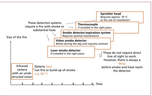
Figure 4 shows the time delay for detecting a large fire for the detection systems listed above.
Waste Incineration
2. Infrared detection and thermal imaging technology with automatic extinguishing
2.1. Short introduction to thermal imaging
Unlike the fire detection systems that have been listed so far, all of which react to smoke or fire, depending on the system type, fire monitoring with infrared (thermal) systems is not fire detection, but temperature monitoring instead.
An infrared detection system sees heat almost immediately.
An infrared early fire-detection system is primarily used to monitor waste processing halls full of stored recycling material. It measures the surface temperature of the recy- cling material without contact.
Should unusual surface temperatures of around 80 °C be detected it and usually indicates the preliminary stage of a fire. Such detection is effected within one tenth of a second.
Fire monitoring of an object with an infrared early fire-detection system therefore means a fire is identified in its formation phase.
Size of the fire
These detection systems require a fire with smoke or
substantial heat.
These do not require direct line of sight to work.
However, there is always a delay
before smoke and heat reach the detector.
Time Detects heat
not fire or build-up of smoke.
e.g. 80 °C Infrared
camera with an unob- structed vision
Sprinkler head Requires approx. 70 °C at the site of installation Thermocouple
if installed in the right place Smoke detector/aspiration system Requires optimal maintenance Video smoke detector
Works during the day and requires contrast Laser smoke detector
If installed in the right place
Figure 4: Fire detection systems in relation to time and required size of fire before triggering when used in waste treatment halls and waste bunkers
Waste Incineration
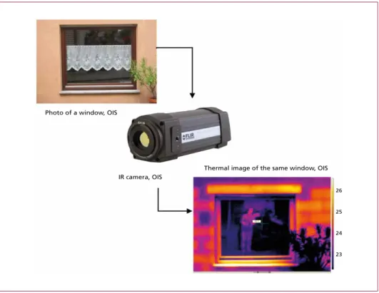
Photo of a window, OIS
IR camera, OIS
Thermal image of the same window, OIS 26
25
24
23
Figure 5: Comparison between a normal photo and a thermal image
Deep seated fires Even pockets of fire deep within a stack of recycling material can be detected.
This is what happens: fire requires oxygen. Once a fire breaks out in a heap of recycling material it can only grow and spread as a result of further kindling. Convection guides air away to the surface through gaps in the pile once the oxygen has been consumed, enabling fresh air with more oxygen to flow in. This heat transfer brings the heat of an underlying fire to the surface. When the infrared detector registers a rapid rise in temperature or if a temperature threshold unusual for the stored material (like 80 °C) is reached, a fire alarm is triggered.
Moreover, the infrared technology allows us to see through smoke. This is very bene- ficial for crane operators in waste bunkers to eliminate fires or hotspots directly into the incineration.
Also, the fire brigade can use the thermal images for orientation and the coordination of their operation. Usually, the smoke would obstruct the operation. Based on the thermal image the hot zones can easily be identified and the core of the fire can be attacked strategically.
Waste Incineration
2.2. Past problems
Infrared early fire detection has been available for many years, but it was often pro- blematic to operate.
Challenges of previous systems:
Tmax 114.21 Tmedium 96.51 Size: 74
• They were not suitable for continuous operation.
• There were many mechanical faults.
Pan-/tilt heads were not laid out for 24/7 operation.
• The only cameras available were those that required cooling, and the Stirling coolers for these cameras needed to be replaced after 600 operating hours.
• There were problems with moving cables.
• The computer capacity required for evaluation and managing disturban- ces did not exist.
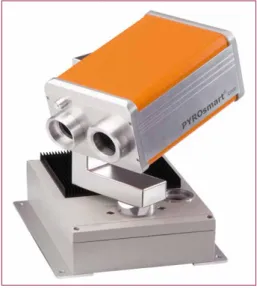
2.3. State-of-the-art technology
Modern infrared early fire detection systems, however, are reliable and can operate continuously without faults.
For cost effectiveness, and to achieve a high local resolution, scanning systems are used in place of large numbers of indi- vidual camera systems. Today, monitoring areas can be displayed in a hemispherical fashion, providing 360° vision.
Operational reliability over many years is now ensured via encapsulated and air- cooled housing.
Systems with high-precision pan and tilt drives designed for continuous operation (ten years or more) are available. These systems provide an unbroken infrared panoramic image, which enables complex objects to be evaluated in great detail.
Figure 6: PYROsmart by Orglmeister Infra- rot-Systeme GmbH & Co. KG
Figure 7: Detection of a disturbance (ex- haust). The temperature threshold for early fire detection is 85 °C. The exhaust (at 114 °C here) does not trigger an alarm
Waste Incineration
Some systems also provide panoramic video images alongside infrared images. In- tegrated cleaning systems ensure continuous cleaning of the lens in moist and dusty environments. Modern systems in recycling plants typically trigger fire alarms at approximately 85 °C.
Disturbances such as hot exhausts of delivery vehicles and wheel loaders, hot engines, lighting, etc., are recognised as such by intelligent infrared fire detection systems. This feature prevents false alarms, and is therefore crucial for the smooth operation of the recycling facility. A simple thermal camera is not able to distinguish between friend or foe.
2.4. Infrared early fire detection
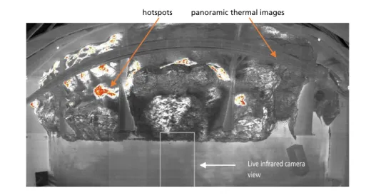
An intelligent infrared detection system creates unbroken high-resolution video and panoramic thermal images, uses these panoramic images to identify hotspots, and calculates 3D target coordinates to control extinguishing systems.
panoramic thermal images hotspots
Live infrared camera view
Figure 8: Panoramic thermal image of an input hall in a recycling plant (3,900 x 7,800 pixel thermal image)
Benefits of panoramic thermal imaging
• Extremely high-resolution thermal images. This makes it possible to detect the smallest temperature changes.
• Immediate overview of hot spots and orientation with the monitored area.
• Much better elimination of disturbances thanks to unbroken image analysis of all adjoining areas.
Infrared detection systems usually provide a user interface.
Waste Incineration
This is typically a terminal contained in a control room, crane cabin or held by the plant fire brigade.
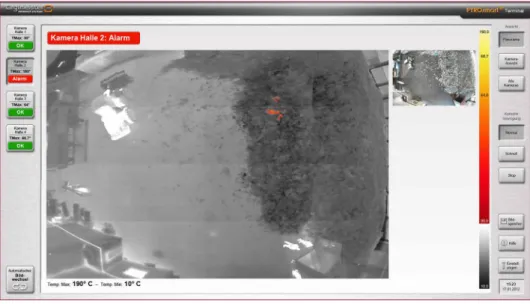
Any hotspots are displayed on the terminal. The user interface for the infrared fire detection system (Figure 9) shows that a hotspot has been detected in a deep level of a heap of recycling material in Hall 2. The maximum temperature (180 °C) is displayed as well. The alarm is also signalled by an audio alert.
At the same time, the potential fire is reported to the central fire alarm system, which immediately notifies the fire brigade. If the fire detection system is connected to an optional extinguishing system, the automatic extinguishing process begins immediately.
Figure 9: Example of a user interface of an infrared fire detection system
2.5. Automatic extinguishing
Infrared systems can precisely control the extinguishing of fires before or as they break out by attacking the hotspot.
The overall goal is an early detection and prevention of major fires with limited use of extinguishing medium.
Depending on the qualities of the stored material, a specific extinguishing procedure is chosen, one of which is described here.
Once the hotspot is detected the infrared system activates the water cannon, and initiates the first extinguishing cycle lasting one minute. The infrared system then immediately checks on the hotspot again to check on temperature changes. If there is a further increase in temperature, it is assumed that the hotspot/fire has not yet been completely cooled down/extinguished. In such cases, the second extinguishing cycle begins automatically. This process continues until the detected temperatures fall below the alarm threshold.
Waste Incineration
Figure 11: Waste bunker Stadtwerke
Düsseldorf Figure 12: Waste bunker Spreerecycling, Spremberg. Here, IR-detection and automatic extinguishing protect four bunker segments
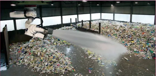
Figure 10: 800 l/min to 6,000 l/min of extinguishing medium is delivered by the water cannon directly onto the hotspot or fire source while it is still small
Source: Rosenbauer International AG, Leonding
Benefits of this extinguishing procedure:
• damage caused by large quantities of regular extinguishing agent by standard pro- cedure is prevented,
• reduced environmental impact and cost,
• interruptions in operation due to damage caused by the extinguishing process are avoided, as only a comparatively small area is affected.
2.6. Application examples
Waste bunkers in waste-to-energy plants
Waste Incineration
Storage and processing: tyres, waste, coal, wood, etc.
Figure 14: Panoramic video image showing outdoor storage of tyres at Heidel- bergCement
Figure 15: Panoramic infrared image showing outdoor storage of tyres at Heidel- bergCement
Figure 16: Combined detection and extin- guishing (IR system and water cannon) outdoor application at a
Figure 17: A ceiling-mounted IR system in a waste input hall
Figure 18: Panoramic infrared image created by an early fire-detection system in the input hall of a recycling plant showing storage areas with higher
Figure 13:
Thermal panoramic image of waste bunker surface at AVA Velsen GmbH
Waste Incineration
2.7. Summary and outlook
The earlier a fire source can be detected and extinguished, the better. It is not difficult to agree on that.
Tmax 100.27 Tmedium 90.57 Size: 16
Figure 19:
Panoramic infrared image by an early fire-detection system in the input hall of a recycling plant – day-time operation
Any new technology, however, needs time to prove it can replace the old solutions reliably, offering progress and improvement. It must withstand the opposition and rejection of established methods and procedures. This is and has been the case for the application of thermal imaging and automatic extinguishing in the field of fire pro- tection, too. By now, a multitude of successfully implemented projects and satisfied users show that what once was regarded as suspiciously innovative is becoming an industry standard.
Since 2015, this is especially reflected by the fact that the VdS’s (VdS Schadenverhütung GmbH, known as Verein der Sachversicherer – German Insurance Association) guideline 3189 on infrared camera units used for monitoring temperatures for fire protection purposes has been available and applied.
The new standard offers improved and approved fire protection along with more peace of mind for the waste industry.
Dorfstraße 51
D-16816 Nietwerder-Neuruppin
Tel. +49.3391-45.45-0 • Fax +49.3391-45.45-10
Waste Management
Order now: www. .de
Karl J. Thomé-Kozmiensky
WASTE MANAGEMENT
Luciano Pelloni
Thomé-Kozmiensky und PelloniWASTE MANAGEMENT
Volume 1 Eastern European Countries
1
Rüdiger Margraf
Waste Incineration
Figure 7:
Rough scheme dry hydration CaO Dosing balance
H2O Dry hydrator CaO
CaO Silo
Ca(OH)2 Ca(OH)2
Silo
towards lime dosing TIC
Several plants in Germany have been provided with this technology.
Figure 8 shows a plant, realised with a dry hydrator for a Ca(OH)2 production capacity of approximately 3 t/h.
Verbrennungs-rost Gewebefilter Elektro- filter Sprüh-
trockner Kamin
Dampf- kessel MüllkranAufgabe-trichter
Müll- bunkerVerbrennungs-luftgebläsevorrichtungAufgabe-Platten-wände TrogkettenfördererEntschlackung/
Ammoniak- Wasser- Eindüsung
Kessel- entaschung
AbgaswäscherDruckerhöhungs-gebläse Adsorbenssilo
Feuerraum Primär-luft
Figure 3:
Karl J. Thomé-Kozmiensky
Volume 2
WASTE MANAGEMENT
Luciano Pelloni
Waste Management Recycling Composting Fermentation Mechanical-Biological Treatment Energy Recovery from Waste Sewage Sludge Treatment
Thomé-Kozmiensky und PelloniWASTE MANAGEMENT
2
2
Thomé-Kozmiensky und Pelloni
Karl J. Thomé-Kozmiensky
Volume 3 Recycling and Recovery
WASTE MANAGEMENT
Stephanie Thiel
WASTE MANAGEMENTThomé-Kozmiensky und Thiel
3
, Thiel
5
2
Thomé-Kozmiensky und Pelloni
Volume 6 Waste-to-Energy
WASTE MANAGEMENT
Stephanie Thiel Karl J. Thomé-Kozmiensky
6
WASTE MANAGEMENTK. J. Thomé-Kozmiensky & S. Thiel
WASTE MANAGEMENT Volume 2
KARL J. THOMÉ-KOZMIENSKY STEPHANIE THIEL HRSG.
Copyright © 2011 TK Verlag Karl Thomé-Kozmiensky Alle Rechte vorbehalten.
Das Einspeisen der Daten in Netzwerke ist untersagt.
WASTE MANAGEMENT Volume 3
KARL J. THOMÉ-KOZMIENSKY STEPHANIE THIEL HRSG.
Copyright © 2011 TK Verlag Karl Thomé-Kozmiensky Alle Rechte vorbehalten.
Das Einspeisen der Daten in Netzwerke ist untersagt.
Waste Management, Volume 1 – 6 • CD Waste Management, Volume 2 and 3
289.00 EUR
save 121.00 EUR
Package Price
Editors: Waste Management, Vol. 1 – 2: Karl J. Thomé-Kozmiensky, Luciano Pelloni Waste Management, Vol. 3 – 6: Karl J. Thomé-Kozmiensky, Stephanie Thiel
Waste Management, Volume 5 (2015) ISBN: 978-3-944310-22-0 120.00 EUR Waste Management, Volume 1 (2010) ISBN: 978-3-935317-48-1 includes translations in Polish, German 20.00 EUR Waste Management, Volume 2 (2011) ISBN: 978-3-935317-69-6 CD includes translations in 50.00 EUR + CD Waste Management, Volume 2 ISBN: 978-3-935317-70-2 Polish and German
Waste Management, Volume 3 (2012) ISBN: 978-3-935317-83-2 CD includes translations in 50.00 EUR + CD Waste Management, Volume 3 ISBN: 978-3-935317-84-9 various languages
Waste Management, Volume 4 (2014) ISBN: 978-3-944310-15-2 50.00 EUR
Waste Management, Volume 6 (2016) ISBN: 978-3-944310-29-9 120.00 EUR
IRRC IRRC
Bibliografische Information der Deutschen Nationalbibliothek Die Deutsche Nationalbibliothek verzeichnet diese Publikation in der Deutschen Nationalbibliografie; detaillierte bibliografische Daten sind im Internet über http://dnb.dnb.de abrufbar
Thomé-Kozmiensky, K. J.; Thiel, S.; Thomé-Kozmiensky, E.;
Winter, F.; Juchelková, D. (Eds.): Waste Management, Volume 7 – Waste-to-Energy – ISBN 978-3-944310-37-4 TK Verlag Karl Thomé-Kozmiensky
Copyright: Elisabeth Thomé-Kozmiensky, M.Sc., Dr.-Ing. Stephanie Thiel All rights reserved
Publisher: TK Verlag Karl Thomé-Kozmiensky • Neuruppin 2017
Editorial office: Dr.-Ing. Stephanie Thiel, Elisabeth Thomé-Kozmiensky, M. Sc.
Janin Burbott-Seidel and Claudia Naumann-Deppe
Layout: Sandra Peters, Anne Kuhlo, Ginette Teske, Claudia Naumann-Deppe, Janin Burbott-Seidel, Gabi Spiegel and Cordula Müller
Printing: Universal Medien GmbH, Munich
This work is protected by copyright. The rights founded by this, particularly those of translation, reprinting, lecturing, extraction of illustrations and tables, broadcasting, micro- filming or reproduction by other means and storing in a retrieval system, remain reserved, even for exploitation only of excerpts. Reproduction of this work or of part of this work, also in individual cases, is only permissible within the limits of the legal provisions of the copyright law of the Federal Republic of Germany from 9 September 1965 in the currently valid revision. There is a fundamental duty to pay for this. Infringements are subject to the penal provisions of the copyright law.
The repeating of commonly used names, trade names, goods descriptions etc. in this work does not permit, even without specific mention, the assumption that such names are to be considered free under the terms of the law concerning goods descriptions and trade mark protection and can thus be used by anyone.
Should reference be made in this work, directly or indirectly, to laws, regulations or guide- lines, e.g. DIN, VDI, VDE, VGB, or these are quoted from, then the publisher cannot ac- cept any guarantee for correctness, completeness or currency. It is recommended to refer to the complete regulations or guidelines in their currently valid versions if required for ones own work.