MBT and SRF
Return of the Experience
in Two RDF Waste-to-Energy Plants in Italy
Luigi Bagnoli, Agostino Calcagno and Davide Rao
1. Refuse Derived Fuel (RDF) ...337 2. Grate combustion system for RDF in the Italian plants ...340 3. Fouling factors ...341 4. The use of Computational Fluid Dynamics (CFD)
for the flue gas prediction ...345 5. References ...348 In recent years, the Waste-to-Energy market in Italy has undergone significant changes, mainly driven by the use of waste with a high calorific value, particularly RDF (Refuse Derived Fuel). Our work will describe the experience gained through the projects of two Italian Waste-to Energy (W-t-E) plants: Pozzilli (IS) and San Vittore del Lazio (FR), during the last 2 years of operation.
The incinerators that burn RDF have some additional criticalities compared to traditi- onal ones, mainly due to the presence of melted ashes, which tend to form important deposits on the surface of the vaporizing screen and on the superheaters too.
Another important element is represented by the particular type of RDF combustion, whose volatile ashes continue to burn, completing the combustion along the radiant chambers.
1. Refuse Derived Fuel (RDF)
In last decades, in Europe (and particularly in Italy) the solid waste and the industrial or commercial one, had changed significantly its composition. This important variation is fundamentally due to the different way of life of citizens in the industrialized countries.
The first Waste-to-Energy plants were characterized by a combustion grate system integrated with an adiabatic chamber, which often was followed by and adiabatic first flue gas pass and then by a heat recovery boiler. The main aim of these industrial plants was the thermal-destruction of solid waste, in order to reduce the volume and the size of municipal waste of the biggest cities. This waste was characterized by a high content of water (moisture) and inert materials, while the content of plastics or combustible materials was very low. This means that the waste was characterized by a low calorific value, about 6 ÷ 8 MJ/kg, forcing to the use of an adiabatic combustion chamber in
MBT and SRF
order to avoid elevated carbon monoxide CO level emissions. Moreover, the steam produced by the boiler was rarely used for industrial purpose or for the production of electrical energy.
In a few decades, the water content of municipal waste has been reduced and, at the same time, the content of plastic materials has increased significantly: the effect was the higher calorific value of waste, higher combustion temperatures and more complex corrosion phenomena.
Nowadays, the Waste-to-Energy plants burn Municipal Solid Waste (MSW), industrial waste or commercial and assimilated one, with a Lower Calorific Value (LCV) of 8 ÷ 14 MJ/kg, up to 16 ÷ 18 MJ/kg, that is twice the original values of the first plants.
However, the municipalities needs have been expanded, with a higher disposal request and more aggressive fuels, increasing the criticality of a heat recovery boiler.
These changes have been accompanied by a different ethical approach in the manage- ment and production of municipal and assimilated waste, a more attentive behavior for the environments problems and recycling, through which there is a partial conversion of waste materials into new ones.
Refuse Derived Fuel (RDF) is a particular type of fuel which can be burned in the Waste-to-Energy plants. It consists of some organic materials, recyclable materials (such as PET or PE plastics), woods, non-recyclable materials, especially chlorine plastics, papers, textiles, plastic-aluminum or plastic-aluminum-paper multi-material packaging, non-chlorinated synthetic rubbers, resins and synthetic fibers.
organic matter
glasses
building wastes electronics
paper plastics
cellulose tetrabricks
metals textiles wood garden wastes
Figure 1:
Typical composition of RDF
Source: Montejo, C.; Martin, R.; Costa, C.; Marquez, M.: Energy Recovery of Reject Fraction of Municipal Solid Waste Resulting from the Mechanical-Biological Treatment Plants. In: Editor Klemes J.J.;
Lam H.L.; Varbanov, P.S.: Chemical en- gineering transactions Volume 21, 2010, pp. 751-756
According to the Lower Calorific Value (LCV) and the chlorine and mercury contents of the mix, different typologies of RDF can be identified. These can be used in cement kiln, in gasification process or they can be burned in dedicated incinerator plants or in co-combustion thermo-electric plants.
MBT and SRF 250,000
200,000
150,000
100,000
50,000 tons/y
total coincineration
plants power plants cement sector cement sector (Associazione Italiana
Tecnico Economica Cemento – AITEC) 0
2010 2011 2012 2013
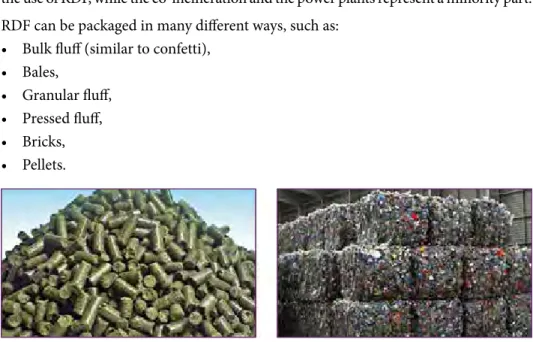
Figure 2: RDF destination in Italy in 2010, 2011 and 2012
Source: ISPRA, AITEC, ENEL
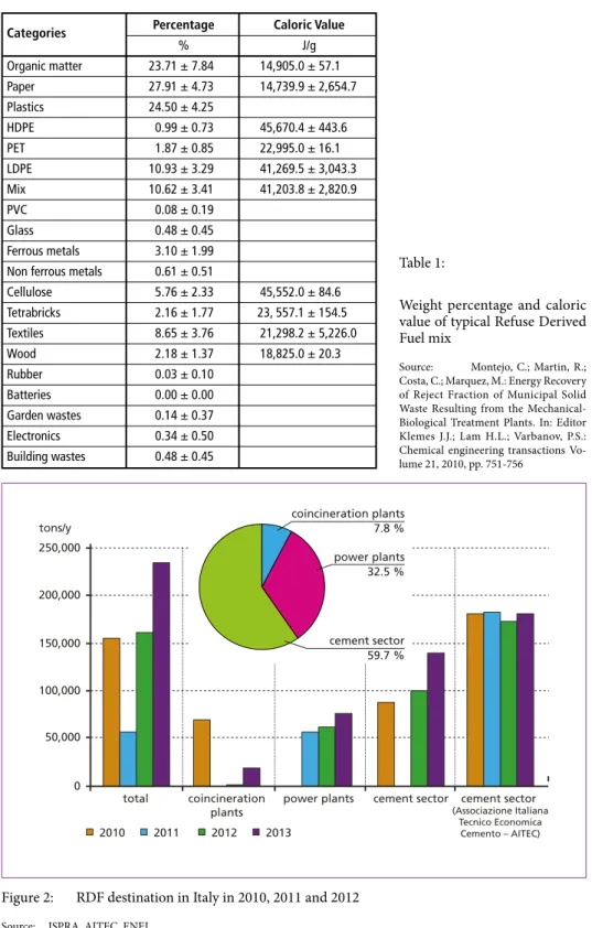
Categories Percentage Caloric Value
% J/g Organic matter 23.71 ± 7.84 14,905.0 ± 57.1
Paper 27.91 ± 4.73 14,739.9 ± 2,654.7
Plastics 24.50 ± 4.25
HDPE 0.99 ± 0.73 45,670.4 ± 443.6
PET 1.87 ± 0.85 22,995.0 ± 16.1
LDPE 10.93 ± 3.29 41,269.5 ± 3,043.3
Mix 10.62 ± 3.41 41,203.8 ± 2,820.9
PVC 0.08 ± 0.19
Glass 0.48 ± 0.45
Ferrous metals 3.10 ± 1.99 Non ferrous metals 0.61 ± 0.51
Cellulose 5.76 ± 2.33 45,552.0 ± 84.6
Tetrabricks 2.16 ± 1.77 23, 557.1 ± 154.5
Textiles 8.65 ± 3.76 21,298.2 ± 5,226.0
Wood 2.18 ± 1.37 18,825.0 ± 20.3
Rubber 0.03 ± 0.10
Batteries 0.00 ± 0.00
Garden wastes 0.14 ± 0.37 Electronics 0.34 ± 0.50 Building wastes 0.48 ± 0.45
Table 1:
Weight percentage and caloric value of typical Refuse Derived Fuel mix
Source: Montejo, C.; Martin, R.;
Costa, C.; Marquez, M.: Energy Recovery of Reject Fraction of Municipal Solid Waste Resulting from the Mechanical- Biological Treatment Plants. In: Editor Klemes J.J.; Lam H.L.; Varbanov, P.S.:
Chemical engineering transactions Vo- lume 21, 2010, pp. 751-756
coincineration plants 7.8 % power plants 32.5 %
cement sector 59.7 %
MBT and SRF
Figure 1 shows that nowadays the cement sector represents the most important one for the use of RDF, while the co-incineration and the power plants represent a minority part.
RDF can be packaged in many different ways, such as:
• Bulk fluff (similar to confetti),
• Bales,
• Granular fluff,
• Pressed fluff,
• Bricks,
• Pellets.
Figure 3: Example of the different forms of RDF packaging: on the left, pellets; on the right, bales
2. Grate combustion system for RDF in the Italian plants
The grate represents the core of the combustion system. Nowadays, there are different types of combustion grate, in order to reach the best combustion efficiency and the lowest pollutants emissions with a large range of fuels.
In fact, the typology of waste, especially RDF, burned in a thermal power plant, can vary significantly from plant to plant: therefore, every combustion grate must be chosen after an accurate analysis of refused mix which must be burned. There are many ways in which the grates can be divided, for example, according to the:
• grate disposition (there are the horizontal grates and the sloped ones),
• grate movement (forward and reverse-acting grates),
• grate cooling system (air cooled, water cooled and air-water cooled).
Other important characteristics which can be variable according to the RDF charac- teristics are the width and the length of the grate.
This article is fundamentally focused on the two Italian Waste-to-Energy plants of Pozzilli (IS) and San Vittore del Lazio (FR).
The combustion system of Pozzilli’s Waste-to-Energy plant is a reverse-acting grate, totally air cooled and it has been chosen in order to reach a large availability with the fuel variation.
MBT and SRF
The grate can burn fuels with a large range of lower heating values, from 11 to 17.5 MJ/kg, it is designed for a nominal throughput of 13.4 t/h and the total width is approximately 6.7 m.
The presence of significative air excess, with a large primary and secondary air flows, may cause particular phenomena. In fact, despite the high combustion efficiency and the low carbon monoxide (CO) production, thanks to the use of special thermal ca- meras we recognized regular flames through all the first radiant chamber and, at the same time, the presence of not totally combusted ashes in the second and third radiant chamber and in the convective pass too. It is important to underline that molted ashes may cause intense fouling phenomena on the exchange surfaces and significant ashes deposits too.
San Vittore del Lazio Waste-to-Energy plant presents a single line grate, wide 6.3 m, partially air and water cooled.
The water cooling system allows the use of high calorific value RDF without problems of local super-heating. Moreover, the water-cooled grate seems to have better results in order to control flue gas temperature. The presence of molted ashes may be lower too.
3. Fouling factors
The correct dimensioning of the boiler’s heat exchange surface can not be separated from a proper knowledge of the fouling phenomena in every part of the thermal units.
The fouling phenomena depend of different factors, such as:
• typology of waste and its chemical composition,
• tube wall temperature of the thermal exchange surface,
• geometrical disposition of the tubes,
• flue gas temperature,
• cleaning systems.
Obviously, an unwanted increase of fouling reduces heat exchange while, on the contrary, a cleaner surface improves the thermal exchange of the unit’s surface, mo- difying the thermal profile of the flue gases in the boiler’s path. So, it is necessary that during engineering phase there is a proper estimation of the boiler’s fouling and, at the same time, it is necessary that the esteemed fouling will be respected during the Waste-to-Energy lifetime. In addition, fouling phenomena change depending on the thermal zone of the boiler: the fouling of the radiative chambers is different from the convective one, and the fouling of a vaporizer unit is different from the superheater one. Moreover, thermal units are more or less cleaned depending on their disposition on the path of the boiler and their geometrical disposition. Finally, the cleaning system has a fundamental role regarding fouling control: the system must be effective, without causing corrosion or erosion phenomena of the tubes.
MBT and SRF
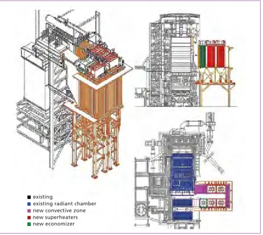
Meanwhile San Vittore del Lazio W-t-E plant is completely a new one erected by our society in 2016, Pozzilli W-t-E plant represents a very important example of revam- ping intervention, modifying in 2017 its vertical arrangement into a horizontal one.
Particularly, this plant was characterized by the removal of the ancient superheaters and vaporizer units from the second and third flue gas passes, the creation of a fourth empty chamber and a new convective zone in membrane walls with four new super- heaters and a new economizer.
The typology of the cleaning system adopted in Pozzilli and San Vittore del Lazio W-t-E plants are the same: normally, it was not foreseen the cleaning operation on the radiative chambers and on the convective one, while all the thermal blocs – including vaporizers, superheaters and economizers – are cleaned by hammers, disposed on their top and handled by electric motors.
This choice proved to be correct during the first months of operation, while after that it was necessary the occasional use of auxiliary cleaning system by controlled explosions, in order to make fall important ashes deposits both on the water walls (Pozzilli) and on some thermal units (San Vittore del Lazio).
Figure 4:
Original configuration of Pozzilli’s W-t-E plant
MBT and SRF Figure 5: New configuration of Pozzilli’s W-t-E plant after the revamping
economizer superheater vaporizer
Figure 6: Configuration of San Vittore del Lazio’s W-t-E plant
MBT and SRF
Particularly, controlled explosions were just used in Pozzilli W-t-E plant, both in the radiative and convective chambers, before the revamping. So, our intervention has re- duced the use of the auxiliary cleaning system, although it did not completely eliminate it. It is important to note that the parts more interested by significative ashes deposits are the inlet and the outlet ducts of the convective zone, because of their geometry and the reduction of section pass: the use of deflectors, installed in order to optimize the flue gas path, has in fact determined deposit accumulation zones.
In San Vittore del Lazio W-t-E plant, the first vaporizer and the first superheater – in the flue gas direction – are particularly interested by ashes deposits. In fact, despite the use of the top hammer cleaning system, successfully used in many other municipal solid waste incinerators, the first two thermal exchange units suffered a more intense fouling phenomenon. As a consequence, an auxiliary cleaning system with explosions is used too.
The other thermal exchange units do not suffer this type of phenomenon, demonstrating the efficacy of our traditional cleaning system.
Thanks to our studies on the two W-t-E plant, it is now possible indicate the cause of this not-expected event. In fact, the RDF combustion is different from the traditional municipal solid waste one, because of its different chemical composition and packaging.
The RDF ashes are more volatile and transportable with the flue gas flow: so, the ashes content of flue gas flow at the inlet of the convective chamber is higher, increasing the fouling phenomenon which is normally present in a W-t-E plant.
Moreover, thanks to the use of special thermal cameras both in the radiative and in the convective chambers, we proved that the particular combustion process of RDF can determine the presence of hot and incandescent ashes along all the radiative chambers
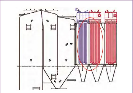
Figure 7:
Inlet duct of the convective cham- ber of Pozzilli W-t-E plant; the red circle indicates the area interested by significative ashes deposits
MBT and SRF
and on the convective pass too. The consequences are important, because the hot ashes – that is with a higher temperature then the flue gas bulk one, are close to their softening temperature, they stick more easily on cold surfaces such as the membrane walls or on the heat exchange surfaces of the thermal blocks.
Figure 8: Inlet duct of the convective chamber of San Vittore del Lazio W-t-E plant; the red circle indicates the area interested by significative ashes deposits – first vaporizer and super- heater
4. The use of Computational Fluid Dynamics (CFD) for the flue gas prediction
The presence of important ashes deposits, especially on the reduction cross section, can improve significantly the flue gas pressure drops. Obviously, elevated flue gas pres- sure drops values indicate important ashes deposits and may compromise the correct operation of the boiler (for example, problems with the flue gas extraction system).
Thanks to our studies on the flue gasses fluid dynamics and the chemical, physical and thermal characteristics of the ashes, are able to avoid the formation of ashes deposits.
Nowadays, the use of Computational Fluid Dynamics (CFD) represents in fact an important help in order to know exactly the flue gas flow pattern along the boiler, its velocity, stream lines distributions, localized and distributed pressure drops, any dead zones and recirculation.
MBT and SRF
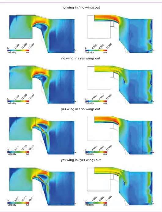
Figure 9: Example of 8 geometric configurations studied for the design of inlet and outlet ducts of Pozzilli W-t-E plant (Italy)
In order to have a correct thermal exchange on the different parts of the boiler, it is necessary to have good local distribution of flue gasses, both in the radiative chambers and in the convective pass. Therefore, a clear knowledge of the flow distribution in the chosen geometric configuration allows to easily identify those solutions which are able to improve the flue gas distribution and its homogeneity.
no wing in / no wings out
no wing in / yes wings out
yes wing in / no wings out
yes wing in / yes wings out
0 6.000 12.000 18.000 Velocity m/s
0 4.000 8.000 12.000 Velocity m/s
0 4.000 8.000 12.000 Velocity m/s
0 4.000 8.000 12.000 Velocity m/s
0 4.000 8.000 12.000 Velocity m/s 0 6.000 12.000 18.000
Velocity m/s
0 6.000 12.000 18.000 Velocity m/s
0 6.000 12.000 18.000 Velocity m/s
MBT and SRF
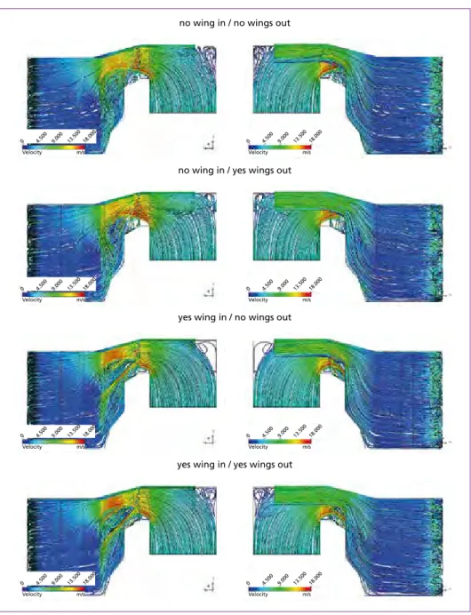
Figure 10: Example of velocity streamlines in the 8 geometric configurations studied for the design of the Pozzilli W-t-E plant (Italy)
Therefore, both in traditional municipal solid W-t-E plants that in the RDF ones, the knowledge of ashes characteristics and behavior, the exact flue gas distribution and the use of deflectors can represent the key-points for a successful W-t-E boiler design.
no wing in / no wings out
no wing in / yes wings out
yes wing in / no wings out
yes wing in / yes wings out
0 4.500 9.000 13.500 18.000
Velocity m/s
0 4.500 9.000 13.500 18.000
Velocity m/s
0 4.500 9.000 13.500 18.000
Velocity m/s
0 4.500 9.000 13.500 18.000
Velocity m/s
0 4.500 9.000 13.500 18.000
Velocity m/s
0 4.500 9.000 13.500 18.000
Velocity m/s
0 4.500 9.000 13.500 18.000
Velocity m/s
0 4.500 9.000 13.500 18.000
Velocity m/s
MBT and SRF
5. References
[1] ISPRA, AITEC, ENEL
[2] Montejo, C.; Martin, R.; Costa, C.; Marquez, M.: Energy Recovery of Reject Fraction of Municipal Solid Waste Resulting from the Mechanical-Biological Treatment Plants. In: Klemes, J. J.; Lam H.L.; Varbanov, P.S. (Eds.): Chemical engineering transactions Volume 21, 2010, pp. 751-756
Contact Person
Dr. Agostino Calcagno Ruths S.p.A.
Chief Executive Officer via Rivarolo 183 r 16161 Genova ITALY
Phone: 0039 - 10 - 741 50 03 Email: agostino.calcagno@ruths.it
Bibliografische Information der Deutschen Nationalbibliothek Die Deutsche Nationalbibliothek verzeichnet diese Publikation in der Deutschen Nationalbibliografie; detaillierte bibliografische Daten sind im Internet über http://dnb.dnb.de abrufbar
Thiel, S.; Thomé-Kozmiensky, E.; Winter, F.; Juchelková, D. (Eds.):
Waste Management, Volume 8 – Waste-to-Energy –
ISBN 978-3-944310-42-8 Thomé-Kozmiensky Verlag GmbH
Copyright: Elisabeth Thomé-Kozmiensky, M.Sc., Dr.-Ing. Stephanie Thiel All rights reserved
Publisher: Thomé-Kozmiensky Verlag GmbH • Neuruppin 2018 Editorial office: Dr.-Ing. Stephanie Thiel, Dr.-Ing. Olaf Holm,
Elisabeth Thomé-Kozmiensky, M.Sc.
Layout: Janin Burbott-Seidel, Ginette Teske, Roland Richter, Cordula Müller, Sarah Pietsch, Gabi Spiegel, Lena Bischkopf
Printing: Universal Medien GmbH, Munich
This work is protected by copyright. The rights founded by this, particularly those of translation, reprinting, lecturing, extraction of illustrations and tables, broadcasting, micro- filming or reproduction by other means and storing in a retrieval system, remain reserved, even for exploitation only of excerpts. Reproduction of this work or of part of this work, also in individual cases, is only permissible within the limits of the legal provisions of the copyright law of the Federal Republic of Germany from 9 September 1965 in the currently valid revision. There is a fundamental duty to pay for this. Infringements are subject to the penal provisions of the copyright law.
The repeating of commonly used names, trade names, goods descriptions etc. in this work does not permit, even without specific mention, the assumption that such names are to be considered free under the terms of the law concerning goods descriptions and trade mark protection and can thus be used by anyone.
Should reference be made in this work, directly or indirectly, to laws, regulations or guide- lines, e.g. DIN, VDI, VDE, VGB, or these are quoted from, then the publisher cannot ac- cept any guarantee for correctness, completeness or currency. It is recommended to refer to the complete regulations or guidelines in their currently valid versions if required for ones own work.