Waste Incineration
Engineered Solutions for the Tuning of Existing Waste-to-Energy Plants
Oliver Gohlke
1. Combustion control upgrades ...197
2. Combustion grate upgrades and improved grate bars ...198
3. Improved secondary combustion ...198
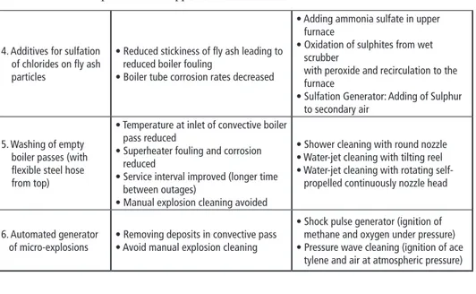
4. Additives for sulfation of chlorides on fly ash particles ...200
5. Washing of empty boiler passes (with flexible steel hose from top) ...201
6. Automated generator of micro-explosions ...204
7. References ...205 Smart engineered solutions have the capacity to boost the performance of waste inci- neration or waste-to-energy plants (WTE). The focus of this paper is on the existing more than 1,600 WTE [1], which operate sometimes with quite old or even outdated equipment. The operation allows to generate relevant amounts of power and heat from mixed municipal waste. A treatment capacity of over 200 million tons of waste per year is at stake.
The potential for performance increase is important and, in many cases, more sustaina- ble than complete new construction. In Table 1 and Figure 1 are given some examples of how the performance and availability of existing plants are improved. The focus is on the combustion system and boiler, which are the core component and most critical part of the WTE process.
Engineered
solutions Effect Examples
1. Combustion control upgrades
• Combustion stability increased (standard deviation of steam flow;
less dips of steam flow)
• Reduction of CO and NOx emissions
• Index-table based controls
• Fuzzy logic and neural net
• Model predictive controllers
• Machine learning
• High-level combustion control with programmed controllers
2. Combustion grate upgrades and improved grate bars
• Availability increased
• Bottom ash burnout improved
• Outage time reduced
• Water cooling of combustion grate avoided
• Improved grate bar shape/design
• Composite grate bars with high grade upper Inconel layer
Table 1: Engineered solutions for the tuning of existing waste-to-energy plants; examples from various operators and suppliers
Waste Incineration
Figure 1: Solutions for improving the performance of existing WTE plants (schematic represen- tation; solutions proposed by Dublix Technology ApS)
4. Additives for sulfation of chlorides on fly ash particles
• Reduced stickiness of fly ash leading to reduced boiler fouling
• Boiler tube corrosion rates decreased
• Adding ammonia sulfate in upper furnace
• Oxidation of sulphites from wet scrubber
with peroxide and recirculation to the furnace
• Sulfation Generator: Adding of Sulphur to secondary air
5. Washing of empty boiler passes (with flexible steel hose from top)
• Temperature at inlet of convective boiler pass reduced
• Superheater fouling and corrosion reduced
• Service interval improved (longer time between outages)
• Manual explosion cleaning avoided
• Shower cleaning with round nozzle
• Water-jet cleaning with tilting reel
• Water-jet cleaning with rotating self- propelled continuously nozzle head
6. Automated generator
of micro-explosions • Removing deposits in convective pass
• Avoid manual explosion cleaning
• Shock pulse generator (ignition of methane and oxygen under pressure)
• Pressure wave cleaning (ignition of ace tylene and air at atmospheric pressure) Table 1: Engineered solutions for the tuning of existing waste-to-energy plants; examples from
various operators and suppliers – continuation –
1. high level combustion control
3. double-jet secondary air
5. water-jet cleaning
3.
4.
2.
6. pressure wave cleaning
steam turbine
fluegas cleaning
4. sulfation generator 2. combustion grate upgrades
Waste Incineration
1. Combustion control upgrades
The main control challenges on WTE plants are uncontrolled variations in the waste heating values and long delays from a control action to full process response. Classical PID controllers are not efficient to cope with such control challenges. Consequently, many WTE plants operates partly in manual operation mode and become dependent on the attention of the operator in charge of the combustion.
Upgrades of existing control systems are possible with systems using index-table based controls, fuzzy logic, neural net, model predictive controllers, machine learning or programmed controllers.
At the IVOO plant in Oostende (Belgium) the registered annual waste treatment capacity could be increased by 6.5 % with the installation of a high level combustion optimization system based on programmed controllers [2].
In another typical example of Figure 2 the combustion optimization resulted in less fluctuation of steam flow as well as higher factual daily production at similar setpoint.
The classical PID controllers of line B lead to high and uneven fluctuation of the steam flow around the setpoint with more important dips than peaks. The situation could be remediated with the optimization of the combustion control based on programmed controllers.
classical control (line B)
optimized control FuzEvent (line A)
time (24 hours)
steam flow t/h
steam flow t/h
Figure 2: Effect of optimized combustion control with FuzEvent; reduced fluctuation of steam flow and increased average steam production
Waste Incineration
2. Combustion grate upgrades and improved grate bars
The core component of most WTE plants is the combustion technology based on a grate system (stoker). Many older plants suffer, because their original grate is not designed for an increased heating value and chloride content of the waste. Combustion grates can be upgraded by improvements in the grate bar design or material choices. In the example of Figure 3 the improved grate bar design is leading to reduced amounts of grate siftings (riddling) and maintenance times.
Figure 3:
Example of improved grate bar design leading to 80 % reduc- tion of grate siftings / riddling and 60 % reduced maintenance time during outage (example of DUB 3 grate bars at the Arezzo plant/Italy)
Another option for increasing grate bar lifetime are the installation of water-cooled grate systems. But in many cases the issues related to the use of water cooling are out- weighing the advantages of reduced thermal wear. Some other successful upgrades consisted of removing water cooled grates with smart designs of air-cooled grate bars.
One example of that are composite grate bars with an upper layer of casted Cr-Ni alloys (Inconel) on a welded standard steel structural basis.
3. Improved secondary combustion
Many efforts were made to improve the secondary combustion with flue gas recircula- tion. The flue gas recirculation is a mean of increasing turbulence without adding air.
This allows in some cases the reduction of the excess air rate and furnace temperatures.
But the need of reduced furnace temperatures can be avoided nowadays by the repla- cement of refractory or SiC tiles with Inconel. That is why flue gas recirculation is not the preferred solution anymore. Systems are removed in order to avoid the inherent risk of leaking flue gas at the pressure side of the flue gas recirculation fan and ducts.
Leaking flue gases are leading to contamination of the boiler house with negative effect on the health of working staff and corrosion of equipment. Numerous severe damages of equipment are reported caused by leaking flue gas recirculation systems.
An alternative to flue gas recirculation are additional levels of secondary air or more radical modifications in the shape of the lower furnace. One example for that is using boiler prism. These measures are effective but quite complicated to install and maintain.
For further description of the effectiveness see [4].
Waste Incineration
Another new option for existing plants in demand of optimization of the secondary com- bustion is the revamping with double-jet secondary air nozzles using supersonic steam jets. This allows a capacity increase and CO reduction without flue gas recirculation.
Figure 4: Double-jet secondary air nozzles with supersonic steam (left: view from boiler house;
right: view from furnace side)
Table 1: Double-jet secondary air nozzles with supersonic steam (BoosterSteam) supersonic double jet secondary air system
• velocity of core beam x 10
• mixing energy x 5
• secondary air flow x 0.5
combustion quality and CO reduction
• CO reduced by > 20 %
• reduced dips in steam flow at situations with low-heating value waste
• no more need of excess secondary air for mixing and controlling cold-CO
• higher furnace temperatures with less excess secondary air
• overall better steam stability and average steam production
increased operation time between outages • reduced flue gas velocities and fly ash carry over
• reduced fouling of convective passes
• no more slagging of secondary air nozzles
• operation time between outages increased
• preterm outage time due to slagging and fouling reduced by 10 %
easy maintenance
• flue gas recirculation avoided
• less explosion cleaning needed
• higher furnace temperatures with clean furnace after outage
Waste Incineration
The technology consists of installing steam injection ports in the secondary air nozzles.
The supersonic injection of steam has a very intense effect of mixing which allows a better burnout of the CO. This also results in a potential reduction of secondary air flow, flue gas flow/velocity and flue gas temperatures at superheater inlet. Furthermore, it is avoided that the secondary air nozzles are slagging with trumpets due to the back flow with suction of hot fly ash against the boiler wall around the nozzles. Overall in- creased performance as well as reduced fouling and corrosion are the consequences.
The Technology was developed at the Muellkraftwerk Schwandorf by Dr. Joerg Krueger and is successfully operated there for over 5 years [4].
4. Additives for sulfation of chlorides on fly ash particles
It is well known that rates of fouling and corrosion of boiler tubes are much higher in WTE plants than in coal fired power plants. The main reason for that is the high chlorine content in the waste that is then deposed on the fly ash particles as chlorides.
These chlorides are composed of alkali and earth alkali metals and even more critical of heavy metals (most relevant Zinc and Lead).
It was shown in numerous cases that the presence of SO3 leads to a rapid sulfation of chlorides: The SO3 reacts with the chloride to a sulphate and HCl is ejected. But the SO3 content in WTE flue gas is very small. More than 99 % of the sulphur contained in the fuel is transformed to SO2, which reacts much slower and does not lead to this positive effect. Stickiness of fly ash and hardness of deposits are drastically reduced by the sulfation. This effect is due to the increased melting point when chlorides are transformed to sulphates.
The sulfation can be achieved by adding ammonia sulphate to the furnace which de- composes to SO3. Another option is the oxidation of sulphites from wet scrubber with peroxide and recirculation to the furnace (injection of sulphates dissolved in water).
Another possibility is the Sulfation Generator (Krueger-Sulfation). This is a new technology, which consist of the injection a sulfur-based reactant through the se- condary air. First plants being successfully upgraded with this technology are in Weener (Germany), Wiesbaden (Germany) and Plymouth (United Kingdom). For further information on this topic see [3] or in the separate paper of Sascha Krueger in this book.
The status of development:
• Very good experience for over 5 years at the Weener plant. (First Generation system)
* Difficult fuel of secondary recovered fuel and car shredder residues
* Massive problem of boiler fouling and corrosion resolved
* Load increase by 15 % (to > 100 t/h of steam)
• 2nd generation system operational in Plymouth (MVV) since end of 2018
Waste Incineration
Features:
• Operation just during and after start-up and boiler cleaning intervals
• Very limited consumption of reactants (< 0,15 kg / t waste; < 0,015 %)
• Specific problems with boiler fouling and corrosion due to combustion of waste are resolved at the root Transformation of Chlorides to Sulphates directly on the surface of the ash particles.
100 1,900
flex steel hose
5. Washing of empty boiler passes (with flexible steel hose from top)
The flue gas temperatures can be reduced by using washing systems introduced to the boiler through the ceiling on a flexible steel hose. This is particularly efficient in the 2nd and 3rd pass as well as the and upper part of the furnace (first boiler pass). The result is a very significant reduction of the flue gas inlet temperatures at superheaters in convective boiler passes.
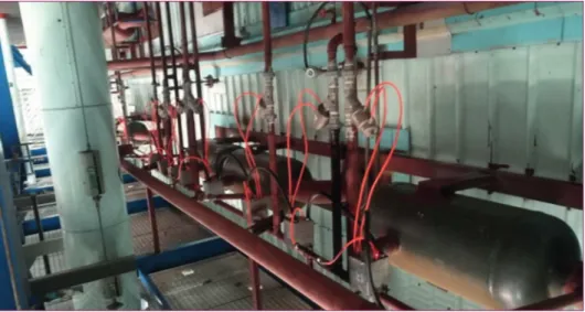
Figure 5:
Sulfation generator (Krueger- sulfation) at the Plymouth refe- rence plant
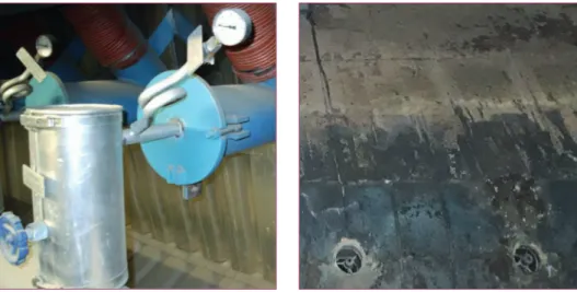
Figure 6:
Side view of boiler with water jet cleaning in 1st (furnace), 2nd and 3rd boiler pass
dosing station injection with secondary air
injection lance detailed injection nozzle
furnace side
Waste Incineration
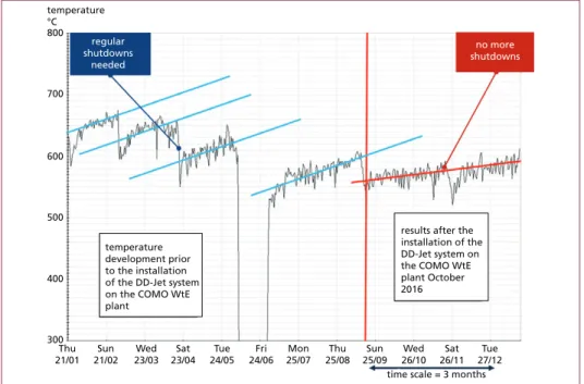
The washing of the empty boiler passes largely reduces its fouling, which leads to lower flue gas temperatures in the following superheaters of the convective passes (as well as evaporators). A decrease by 50 to 100 °C can be achieved with the revamping of such washing systems. The consequences are reduced fouling and corrosion rates of the superheaters. This leads to overall improvement of service intervals (time between outages) and availability. In Figure 8 is shown the evolution of the flue gas temperature over several months before and after installation of a water-jet cleaning system.
10,400
boiler
1,780
air seal blower
1,320 control cabinet
Figure 7:
Top view of same boiler (boiler width 10,8 m with 2 cleaning openings per boiler pass;
1 single system moves between 6 openings)
300 400 500
temperature development prior to the installation of the DD-Jet system on the COMO WtE plant
time scale = 3 months Thu
21/01 Sun 21/02
Wed 23/03
Sat 23/04
Tue 24/05
Fri 24/06
Mon 25/07
Thu 25/08
Sun 25/09
Wed 26/10
Sat 26/11
Tue 27/12 results after the installation of the DD-Jet system on the COMO WtE plant October 2016 600
700 800 temperature
°C
regular shutdowns
needed
no more shutdowns
Figure 8: Effect of water jet cleaning on flue gas temperature and boiler availability; this example is from the Como/Italy WTE plant (different from examples in other figures)
Waste Incineration
Different nozzle types are used for the washing of empty boiler passes:
• round nozzle with variable slid (360-degree spray; shower)
• nozzle head with directional single nozzles and tilting of reel
• nozzle head with directional single nozzles and self-propelled rotation
Systems are particularly efficient with a rotating nozzle head. A slow rotation speed of 10–20 turns per minute is important in order to create a directional beam of water reaching the boiler walls with low pressure. Boiler walls can be reached up to 6 m from the nozzle head with a very good cleaning result. Examples of successful realization of such upgrades are in Como (Italy), Weener (Germany) and Shinseung (South Korea).
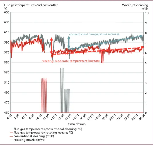
Figure 9: Effect of water jet cleaning on flue gas temperature outlet 2nd pass (inlet convective pass);
comparison of conventional system versus self-propelled rotating nozzle; two different days on same time scale; cleaning 8 times in second pass between 12:30 and 14:00 with the conventional system (grey) and the next day cleaning between 10:00 and 11:00 at 5 times with rotating nozzle (red)
450
6:00 7:00 8:00 9:00 10:00 11:00 12:00 13:00 14:00 15:00 16:00 17:00 18:00 19:00 20:00 21:00 22:00 23:00 00:00 0 1 2 3 4 5 6 7 8 9 10
470
time hh:mm 490
510 530 550 570 590 610 630 650
Flue gas temperatures 2nd pass outlet
°C
Water-jet cleaning m3/h
conventional: temperature increase
rotating: moderate temperature increase
flue gas temperature (conventional cleaning; °C) flue gas temperature (rotating nozzle; °C) conventional cleaning (m3/h)
rotating nozzle (m3/h)
Waste Incineration
6. Automated generator of micro-explosions
The convective passes of WTE boilers are typically equipped with steam soot blowers or rapping devices (hammers). But fouling and even clogging or obstruction of the tube bundles in the convective passes remain a critical factor for the availability and service intervals of WTE plants. This mainly due to the difficult composition of WTE fly ashes and sometimes in older plants made worse by poor boiler design as well as difficult maintenance of rapping devices or sootblowers..
That is why it became common to use additional explosion cleaning in WTE boilers.
In most cases this is done manually using lances. These lances carry either explosive charges or bags filled with explosive gases. They are introduced via boiler service doors (manholes) during operation.
The cleaning result of such manual explosions can be quite good. But it is costly as the explosion cleaning teams must travel for each campaign. Furthermore, it remains critical safety wise.
An alternative are automated explosion cleaning systems. These are also called shock pulse generators or pressure wave generators. It consists of a vessel (steel container) which is fixed at the outside of the boiler at the most critical locations of boiler fouling and blockages. A system using compressed gases is described in [3]. During the explosion of the gases a release valve opens and allows the shock wave to enter the boiler.
Another new system (pressure wave generator or DX-Wave supplied by Dublix Tech- nology ApS) is described in Figure 10. This system works with explosive gases under atmospheric pressure which are very slowly filled into a vessel. The vessel is fixed to the outside of the boiler. That way it can be kept open to the furnace and does not require a release valve. The system is isolated from the furnace by sealing air. The gas is igni- ted, and the resulting micro-explosion generates the pressure wave, which is directly released to the boiler (without action of any release valve). This gives the system a high degree of inherent safety.
Figure 10: Boiler cleaning with pressure wave boiler cleaning (automated explosion cleaning)
Waste Incineration
7. References
[1] Columbia University, Watste to Energy Research and Technology Council: 1600 Waste to Ener- gy-facilities in the World. Online available: http://www.seas.columbia.edu/earth/wtert/sofos/
WTE_Plants.xlsx
[2] Dublix Technology ApS, Copenhagen/Denmark. Online available: https://www.dublix.com/
solutions/combustion-control#testimonials
[3] Krüger, S.; Krüger, J.: Optimierung von Verbrennungsanlagen – Praxiserfahrungen bei der Verbrennung von Abfällen, EBS und Biomassen – einfache Umsetzung – große Wirkung. In:
Thomé-Kozmiensky, K. J.; Beckmann, M. (Hrsg.): Energie aus Abfall, Band 12. Neuruppin: TK Verlag Karl Thomé-Kozmiensky, 2015, S. 25-52. ISBN: 978-3-944310-18-3). Online available:
http://www.vivis.de/phocadownload/Download/2015_eaa/2015_EaA_25_39_Krueger_1.pdf [4] Schu, R.; Born, M.: Erhöhung der Energieeffizienz bei Abfallverbrennungsanlagen durch Pro-
zessführung und Anlagenschaltung. In: Thomé-Kozmiensky, K. J.; Beckmann, M. (Hrsg.): Op- timierung der Abfallverbrennung 3. Neuruppin: TK Verlag Karl Thomé-Kozmiensky, 2006, S. 283-326. ISBN: 978-3-935317-21-4). Online available: http://www.ecoenergy.de/go_public/
freigegeben/BiFuelCycle_Vivis_Maerz%202006.pdf
[5] Steiner, C.; Ninck, K.: Online Cleaning with Shock Pulse Generators – Current Experience.
Online available: https://cdn.waste-management-world.com/902/0-0-0/1/-/online-spg-twinl- cleaning-experiences-en-161012.pdf
Contact Person
Dr. Oliver Gohlke Dublix Technology ApS Technology Director
Technology (Engineering and Development) Grusbakken 10, 1
2820 Gentofte/Copenhagen DENMARK
+45 45650540 (Copenhagen office) og@dublix.com
Bibliografische Information der Deutschen Nationalbibliothek Die Deutsche Nationalbibliothek verzeichnet diese Publikation in der Deutschen Nationalbibliografie; detaillierte bibliografische Daten sind im Internet über http://dnb.dnb.de abrufbar
Thiel, S.; Thomé-Kozmiensky, E.; Winter, F.; Juchelková, D. (Eds.):
Waste Management, Volume 9 – Waste-to-Energy –
ISBN 978-3-944310-48-0 Thomé-Kozmiensky Verlag GmbH
Copyright: Elisabeth Thomé-Kozmiensky, M.Sc., Dr.-Ing. Stephanie Thiel All rights reserved
Publisher: Thomé-Kozmiensky Verlag GmbH • Neuruppin 2019 Editorial office: Dr.-Ing. Stephanie Thiel, Elisabeth Thomé-Kozmiensky, M.Sc.
Layout: Claudia Naumann-Deppe, Janin Burbott-Seidel, Sarah Pietsch, Ginette Teske, Roland Richter, Cordula Müller, Gabi Spiegel Printing: Universal Medien GmbH, Munich
This work is protected by copyright. The rights founded by this, particularly those of translation, reprinting, lecturing, extraction of illustrations and tables, broadcasting, micro- filming or reproduction by other means and storing in a retrieval system, remain reserved, even for exploitation only of excerpts. Reproduction of this work or of part of this work, also in individual cases, is only permissible within the limits of the legal provisions of the copyright law of the Federal Republic of Germany from 9 September 1965 in the currently valid revision. There is a fundamental duty to pay for this. Infringements are subject to the penal provisions of the copyright law.
The repeating of commonly used names, trade names, goods descriptions etc. in this work does not permit, even without specific mention, the assumption that such names are to be considered free under the terms of the law concerning goods descriptions and trade mark protection and can thus be used by anyone.
Should reference be made in this work, directly or indirectly, to laws, regulations or guide- lines, e.g. DIN, VDI, VDE, VGB, or these are quoted from, then the publisher cannot ac- cept any guarantee for correctness, completeness or currency. It is recommended to refer to the complete regulations or guidelines in their currently valid versions if required for ones own work.