455 Concepts for processing solid SRF
Concepts for Processing Solid Recovered Fuels of Different Waste Origins for Waste-to-Energy Plants
Jürgen Deditz, Michael Pinkel and Roland Pomberger
1. General principles ...455
2. Definition of alternative fuel ...456
2.1. Definition and added-value characteristics of alternative fuels ...456
2.2. Origin of alternative Fuels ...457
2.3. General classification of alternative fuels ...458
2.3.1. The high-calorie fraction ...458
2.3.2. The medium-calorie fraction ...458
2.3.3. The low-calorie fraction ...458
2.4. Requirements of and demands on alternative fuels ...458
2.4.1. Physical characteristics and calorific value ...459
2.4.2. Technological requirements...459
3. Processing concepts for preparation ...460
3.1. Concept 0 – waste pre-treatment ...463
3.2. Concept 1 – location in Germany ...463
3.3. Concept 2 – location in Estonia ...466
3.4. Concept 3 – location in Austria ...468
1. General principles
Waste-to-energy plants represent a major building block in a coordinated waste ma- nagement system. To make the best use of the energy content in waste, the alternative fuels recovered are used in the most varied plants. The applications range from the main burner in a cement plant to the traditional grate combustion plant. In line with this, the preparation processes are also very heavily dependent on the requirements – parame- ters – of the relevant fuel, taking into account its area of application. The use of varied pre-treatment stages – key phrase - selective crushing – through to differentiated final preparation – granule size distinction for 2D-3D materials, chlorine load reduction etc. – is dependent on the parameters required by the relevant user and also on the origin of the material to be prepared – domestic refuse, remains of separately collected
Jürgen Deditz, Michael Pinkel, Roland Pomberger
456
packaging waste, commercial waste, bulky waste. Before specifying a processing concept it is therefore essential not only to know the incoming flows of materials and hence the composition of the input material but also users’ specifications and requirements regarding the output product.
In general, with all concepts one may assume that some extraction of materials with recycling value has already occurred with any valuable waste.
2. Definition of alternative fuel
2.1. Definition and added-value characteristics of alternative fuels
Alternative fuels – or Solid Recovered Fuels –, which are also known as secondary fuels are used as substitutes for primary fuels i.e. fossil fuels such as coal – brown coal and anthracite –, petroleum, natural gas and peat. Alternative fuels are therefore sources of energy from waste that are suitable for energy generation and which are used on their own or in a relevant proportion for energy extraction and in doing so meet relevant quality criteria.
Various demands are made of alternative fuels by their users. For one thing, there are requirements regarding the following physical characteristics:
• moisture,
• granule size,
• density – differences between fluff, pellets and balls –.
For another, the following technical combustion and chemical properties are of interest:
• calorific value, specific energy content,
• flash point,
• chemical composition e.g. level of heavy metals, halogens,
• carbon and hydrogen,
• level of ash and/or its composition,
• hazardous substance classification to individual groups of materials.
In order to be able to carry the preparation of the waste flows used through to a high- quality alternative fuel, knowledge of potential hazardous substances and the physical characteristics of individual groups of materials is of central importance. Then one can prepare materials in a targeted manner according to groups of materials high in calorific value and free of hazardous substances, taking into account their physical behaviour in the most varied mechanical preparation stages.
457 Concepts for processing solid SRF
Figure 1: Solid recovered fuel chain
2.2. Origin of alternative Fuels
As can be seen in practice, very different waste flows containing groups of materials with a high calorific value may be drawn upon for the production of alternative fuels.
Alternative fuels may be produced from the most varied waste such as organic waste, mixed or separately collected municipal waste or from special batches from commerce and industry.
The main material flows for the production of alternative fuels are:
• Pre-treated flows of materials enriched with fractions with high calorific value from the sector of mechanical sorting – sorting residues from treatment plants already simply pre-treated.
• Screen overspills enriched with fractions with high calorific value from the sector of organic treatment of residual waste – mechanical organic waste treatment.
• Industrial and commercial waste direct from collection.
• Flows of parts from the construction site waste sector – in particular mixed skips with a high proportion of fractions with high calorific value such as cartons, films, timber etc.
• Flows of parts from the preparation of municipal waste generally.
So in the preparation of waste flows to make alternative fuels one may assume very different waste flows. Major criteria for assessing whether waste is suitable for prepa- ration to make an alternative fuel are:
• Can the waste be extracted by mechanical treatment steps?
• Can an alternative fuel fraction be economically separated from the extracted mix of waste?
• Can the product be stored?
Non- hazardous
waste
Sampling and test methods Production and trade of
Solid Recovered Fuels
Point of (waste) reception
Point of (SRF) delivery QMS
Agreed acceptance criteria
Classification Customer-specific
requirements
Specification template Terminology
Use of classified fuel
Jürgen Deditz, Michael Pinkel, Roland Pomberger
458
2.3. General classification of alternative fuels
Alternative fuels can be classified by their calorific value into groups that are significant with regard to their use. The statements on the calorific value window are described under the usual sector classifications.
2.3.1. The high-calorie fraction
This is primarily extracted by air separation but also by separation using pneumatic/
mechanical separators such as ballistic separators from the pre-crushed bulk flow. This fraction has the highest calorific value, which lies between 18,000 and 24,000 kJ per kilogram depending on the input material. The main components of this fraction are plastic films, fabrics, paper and carton components. This grade is used primarily in the primary combustion sector of the cement industry. For this use, crushing to a gra- nule size of 15 to 35 millimetres is also necessary. For technological reasons, there are stringent requirements of freedom from impurities since the rapidly running crushing processes react in a very sensitive manner to impurities in the area of the rotors and cogs.
2.3.2. The medium-calorie fraction
This fraction is prepared to a granule size in the range of 50 to 75 millimetres and with a relatively high calorific value – 15,000 to 18,000 kJ per kilogram – is used in the sector of secondary combustion in cement works and with a calorific value of about 13,000 to 17,000 kJ/kg in the sector of whirlwind separation combustion. Production normally occurs following separation of the light fraction and is achieved via various heavy particle ejections – inert material traps –, screening stages and metal separation devices. In the use of alternative fuels in cement kilns, inert impurities are undesirable and therefore they reduce quality. It is otherwise in whirlwind separation plants, where inert impurities are of less importance. This gives rise to different requirements in preparation depending on the plants in which this alternative fuel is to be used.
2.3.3. The low-calorie fraction
One speaks of low-calorie fractions when the calorific value is smaller than 12,000 kJ per kilogram. This fraction occurs as the sorting residue from the preparation of fuels from waste flows. Since the cost of disposal in the sector of refuse combustion plants is significantly above the cost of recycling in the cement works sector and whirlwind separation plants, every operator is interested in keeping the volume of this material flow as small as possible. For this reason, fine fraction proportions are sometimes ejected and prepared for direct deposit on waste disposal sites via organic subsequent treatment processes.
2.4. Requirements of and demands on alternative fuels
As already mentioned above, the quality requirements upon alternative fuels are for one thing dictated by the customer and for another defined by environmental consi- derations. One major requirement of a commodity is that uniform standards apply to
459 Concepts for processing solid SRF
it, permitting trade across borders and making it easier for plants to obtain permission to use it as an alternative fuel that is quality-assured as it is specified by standards. The EU’s aim is to make alternative fuels into a tradable commodity in order to further promote the recycling of waste.
2.4.1. Physical characteristics and calorific value In general, to permit the development of separation techniques for specific groups of materials, the physical characteristics in each case and the volumes of these groups of materials available in the waste flows are important. Here the geometrical dimensions in particular of individual groups of materials are also of interest.
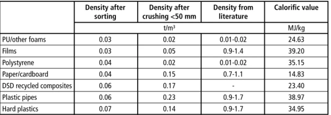
The table below shows the specific density and also the calorific value of fractions of interest for the production of alternative fuels from waste flows. The figures relate to a prepared condition of the individual groups of materials and also to after crushing to about fifty millimetres.
Table 1: Density and calorific value of fractions Density and calorific value of fractions for the production of alternative fuels from waste flows
Density after Density after Density from Calorific value sorting crushing <50 mm literature
t/m³ MJ/kg PU/other foams 0.03 0.02 0.01-0.02 24.63
Films 0.03 0.05 0.9-1.4 39.20
Polystyrene 0.04 0.02 0.01-0.02 35.15
Paper/cardboard 0.04 0.15 0.7-1.1 14.83 DSD recycled composites 0.06 0.17 - 23.40 Plastic pipes 0.06 0.23 0.9-1.7 38.97 Hard plastics 0.07 0.14 0.9-1.7 34.95
Correlations are sought so as to characterise the fractions in order to permit the targeted use of separation techniques for the production of alternative fuels.
Because of the often-used separation by density – e.g. in air separation – the correlation between density and calorific value can be seen in the following presentation. A trend may be discerned in which the lighter groups of materials in the mix of waste have a higher calorific value.
2.4.2. Technological requirements The requirements of the cement industry regarding alternative fuels At the moment the cement industry is one of the major customers for alternative fu- els. The cement industry uses various types of waste – such as industrial slurries and various chemicals high in calorific value – and has gained decades of experience in dealing with alternative fuels. Here alternative fuels are mixed in with primary fuels in
Jürgen Deditz, Michael Pinkel, Roland Pomberger
460
practically every mixing proportion up to almost 95 percent, with primary fuels still being used only for starting up and shutting down the cement kiln and for control of the process. The increase in the rate of use and the proportion of alternative fuels is accompanied by an increase in requirements as to the quality of the alternative fuel.
However, chlorine in particular is a limiting factor here. The requirements generally referred to with regard to alternative fuels for use in the cement industry are:
• energy content: larger than 20 MJoules per kg of dry substance
• chlorine content: less than 0.5 percent to 1.0 percent on average, possibly up to 3 percent
Industrial power stations
Another area of use that also has many years of experience is combined combustion in industrial plants. In industrial power stations, whirlwind separation technology is the technology of choice because of its high level of controllability. Here all mixing proportions are possible but power is mainly generated from one hundred percent alternative fuel. In Austria this technology has been used since the early eighties by industries with high energy requirements – e.g. paper and cellulose manufacture – and it is state of the art. The requirements generally referred to with regard to alternative fuel for use in industrial power stations with whirlwind separation technology are:
• energy content: 13.5 MJoules per kg of dry substance on average, with a spread of 8 to 18 MJoules per kg of dry substance
• chlorine content: less than 0.5 percent to 0.8 percent on average, possibly up to 3 percent
Coal power stations
Alternative fuels were first used on a large scale in big coal power stations in 2000 in the Netherlands, Germany and to a limited extent also in Austria. The requirements generally referred to with regard to the alternative fuel for use in coal power stations are:
• energy content: 13.5 MJoules per kg of dry substance on average, with a spread of 8 to 18 MJoules per kg of dry substance
• chlorine content: less than 0.6 percent on average, possibly up to 2.5 percent With regard to the chlorine content it should be borne in mind that the total chlorine content in the fuel mixture must be less than 0.2 percent – up to a maximum of 0.4 percent–.
3. Processing concepts for preparation
Three different processing concepts for the production of alternative fuels are presented below. What all three processing concepts have in common is that residual waste is not delivered directly from the municipal sector but is at least crushed in what are known as decentralised pre-treatment plants and then a fine fraction of smaller than forty to
463 Concepts for processing solid SRF
sixty millimetres is separated via a screen. However, this fraction as such is not suitable for the production of a high-quality alternative fuel. The screen overspill then goes into the plants shown below as input material.
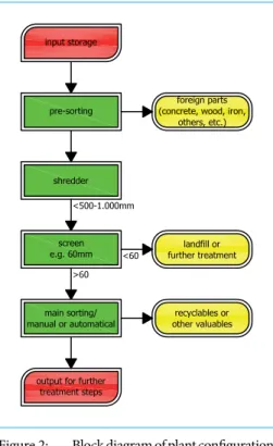
3.1. Concept 0 – waste pre-treatment
In the following concepts, 1 and 3, a concept of decentralised pre-treatment of domestic and residual refuse, bulk refuse and/or other mixed waste flows and centralised pre- paration for a fuel ready for combustion is used. Below a simple pre-treatment plant is presented that could also be used for the concepts shown below of the various al- ternative fuel plants.
The waste supplied is subjected to a pre- sort and any impurities not suitable for storage and any valuable materials are removed before further treatment. The treatment is carried out via a crushing sta- ge that serves mainly to homogenise the waste for the following treatment stages, accompanied by a subsequent separation by screening. Any metal may be removed before screening by a magnetic separator over the belt. The screen overflow, which as a rule is larger than sixty to one hund- red millimetres, should be fed to a process of manual or automatic removal of valua- ble materials so as to safeguard resources.
However, it may also go directly into the manufacture of the alternative fuel.
Depending on local conditions and the origin of the waste, the material passing through the screen may also be input to thermal recycling or to organic treatment.
Figure 2: Block diagram of plant configuration – concept 0
3.2. Concept 1 – location in Germany
The specific operating plant is located in Germany and has been in operation in its present plant configuration since 2011. The operating plant was set up on the premises of a paper factory and serves to supply a fluidized bed burner with alternative fuels from the refuse sector.
Jürgen Deditz, Michael Pinkel, Roland Pomberger
464 Task
Preparation of pre-treated waste fractions from domestic refuse or from the commercial and industrial waste sectors to make an alternative fuel with the required quality cha- racteristics. The pre-treated input material must meet a minimum standard with regard to granule size and calorific value. This is as a rule achieved by simple pre-crushing and separation by screening.
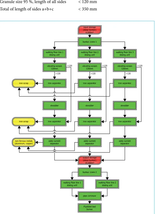
The plant consists of the following departments:
• input control,
• interim storage of input material – flat bunker with 6,000 m³,
• handling with crane,
• feed-dosing unit,
• inclined screen to sreen fraction smaller than one hundred millimetres,
• over belt magnet to separate ferrous metals from the overflow material stream,
• secondary crushing smaller than one hundred millimetres,
• separation of ferrous and non-ferrous metals with overbelt magnet and NE-sepa- rator of the entire fraction smaller than one hundred millimetres,
• interim storage of output material – flat bunker with 6,000 m³,
• automatic storage system – bunker crane,
• output belt conveyer to fluidized bed incineration.
Plant details
Nominal output 3 x 25 tonnes/hour Operating weeks 48 weeks/year Operating days 7 days/week
Operating hours 21 operating hours/day Theoretical capacity ~ 530,000 tonnes/year Actual capacity ~ 350,000 tonnes/year Quality of input material
Granule size 100 % < 300 x 300 mm Granule size 50 % < 100 x 100 mm
Foreign bodies – metal, glass etc. < 5 % of input by weight of dry substance Calorific value – 100 s 11,000 to 24,000 kJ/kg
Average calorific value – 100 s > 14,000 kJ/kg
465 Concepts for processing solid SRF
Quality of output material:
Granule size 100 %, length of all sides < 250 mm Granule size 95 %, length of all sides < 120 mm Total of length of sides a+b+c < 350 mm
Figure 3: Block diagram of plant configuration – concept 1
Jürgen Deditz, Michael Pinkel, Roland Pomberger
466
Figure 4: Shredder – 3 lines–
3.3. Concept 2 – location in Estonia
The specific operating plant is located in Estonia on its own operating plant site wit- hout a thermal recycling plant. The plant has been operating since 2012. In contrast to Concepts 1 and 3, the waste is taken in without pre-treatment.
Task
Preparation of waste fractions from domestic refuse or the commercial refuse sector without pre-treatment. The aim is to produce an alternative fuel for use in the cement industry in the main burner.
The plant consists of the following departments:
• goods in inspection
• interim storage of input material in the flat bunker
• pre-crushing
• separation of iron
• screening into fractions of smaller than one hundred millimetres and larger than one hundred millimetres
• air separation of the fraction of larger than one hundred millimetres
• subsequent crushing of the light fraction of larger than one hundred millimetres to smaller than 25 millimetres
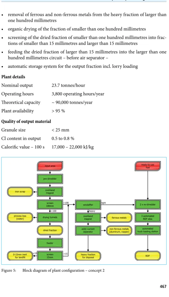
467 Concepts for processing solid SRF
• removal of ferrous and non-ferrous metals from the heavy fraction of larger than one hundred millimetres
• organic drying of the fraction of smaller than one hundred millimetres
• screening of the dried fraction of smaller than one hundred millimetres into frac- tions of smaller than 15 millimetres and larger than 15 millimetres
• feeding the dried fraction of larger than 15 millimetres into the larger than one hundred millimetres circuit – before air separator –
• automatic storage system for the output fraction incl. lorry loading Plant details
Nominal output 23.7 tonnes/hour
Operating hours 3,800 operating hours/year Theoretical capacity ~ 90,000 tonnes/year Plant availability > 95 %
Quality of output material
Granule size < 25 mm Cl content in output 0.5 to 0.8 %
Calorific value – 100 s 17,000 – 22,000 kJ/kg
Figure 5: Block diagram of plant configuration – concept 2
Jürgen Deditz, Michael Pinkel, Roland Pomberger
468
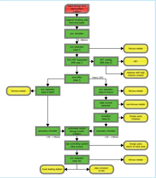
3.4. Concept 3 – location in Austria
The specific operating plant is located in Austria and has been operating in its present plant configuration since 2012. However, it had already achieved expansion stage 1 by 2003. The operating plant was set up on the premises of a cement plant and serves to supply the cement kiln with alternative fuels from the refuse sector for use in the main burner. About sixty percent of production volume is sent to other users via a lorry loading bay.
Task
Preparation of pre-treated waste fractions from the domestic refuse or commercial refuse sector and separately collected waste fractions with a high calorific value not to be recycled as materials, to be made into an alternative fuel. The pre-treatment must include at least the ejection of biogenic waste components as well as large proportions of inert materials.
The plant consists of the following departments
• input control
• interim storage of input material – flat bunker 2,000 m³ –
• input storage handling with wheel loader
• pre-crushing smaller than 250 millimetres
• first separation of ferrous metals with overbelt magnet
• output of high chlorine content particulars by NIR sorters
• seperation in a light fraction – foils and thin walled plastic parts – and a heavy fraction – hollow parts, non ferrous parts, wood etc. – by air separation
Figure 6:
Screening plant
469 Concepts for processing solid SRF
Figure 7: Block diagram of plant configuration – concept 3
Figure 8:
Output material
Jürgen Deditz, Michael Pinkel, Roland Pomberger
470
• secondary crushing of light fraction to a grain size smaller than 30 to 35 mm
• secondary separation of ferrous and non-ferrous metals from the heavy fraction with overbelt magnet and NE-separator
• heavy part separator – wood, inert materials – by a secondary air separation step
• secondary crushing of heavy fraction to a grain size smaller than 15 to 25 mm
• interim storage of output material with a capacity of at least 4,500 m³ including automatic storage systems
• automatic discharge system with contaminant control – particle size and fine steel discharge by a drum magnet –
• dispatch logistics by truck loading or pipe conveyor to the cement kiln
Plant details:
Nominal output 12.5 tonnes/hour Operating weeks 50 weeks/year Operating days 7 days/week
Operating hours 22.5 operating hours/day Theoretical capacity ~ 99,000 tonnes/year Plant availability > 92 %
Quality of output material:
Granule size 2D 30 x 30 x 0.3 mm
Granule size 3D 15 x 15 x 5 mm
Ejection - ferrous metals 97 % of actual input Ejection rate- non-ferrous metals 95 % of actual input Proportion of good material 25 % of the ejected fraction Cl content of output < 0.7 %
Cl content of rejected fraction > 12 % Average calorific value – 100 s – > 18,500 kJ/kg