Waste Incineration
Automated Radiation Pass Cleaning in Waste-to-Energy Plants
– Experience from More than 70 Shock Pulse Generator Installations –
Kaspar Ninck and Christian Mosbeck
1. Why modern waste to energy plants need a system to automatically
remove slag/deposits in radiation passes during boiler operation? ...257
2. History of radiation pass cleaning in waste to energy plants ...258
3. SPG radiation pass cleaning – chosen references ...259
3.1. Reference A – cleaning a radiation pass upstream of the SPG...260
3.2. Reference B – replacing water canons ...261
3.3. Reference C – replacing shower cleaning system ...261
3.4. Reference D – furnace pass and screen grid cleaning ...262
3.5. Reference E – newbuilt with radiation pass Inconel cladding ...262
3.6. Reference F – 100 t/h boiler with clean radiation passes ...262
4. SPG radiation pass cleaning – different types for different radiation passes ...263
5. Operating expenditures and benefits...264
6. References ...264 In contrast to previously often applied automated radiation pass cleaning technologies as Shower Cleaning, Water Canons and Wall Blowers, all running on water or steam, the Shock Pulse Generator (SPG) automatically creates powerful shock waves by pres- surized gas combustion [4]. A comparison of the cleaning performance achieved for six installations is presented. Based on 70+ SPGs installed in radiation passes of waste to energy plants world wide, design guidelines for the implementation for retrofits and new builts is given. Typical information about operating expenditures are then put into relation to customer benefits.
1. Why modern waste to energy plants need a system to automatically remove slag/deposits in radiation passes during boiler operation?
A waste to energy boiler consists of different sections. In the schematical drawing in Figure 1 the green box shows an economizer bundle, i.e. feed water is heated close to saturation temperature. Blue boxes or sections show evaporator bundles or panels
Waste Incineration
and red boxes show superheater bundles. The colour profile shifting from dark red (grate/furnace on the left) to clear yellow (at the boiler outlet to the right) shows the flue gases being cooled down from about 1,200 °C to 150-200 °C.
Since waste is a resource to produce elec- tricity and heat, waste to energy plants are designed to use this resource most efficiently. In order to maximise thermal efficiency steam should be superheated to the highest possible temperatures.
Hence on one hand superheater bundles or panels should be placed as closely to the furnace as possible. On the other hand there is the risk of superheater corrosi- on [3]. If the tube material reaches too high temperatures superheater tubes are damaged quickly due to chlorine attack of the metal matrix. Therefore, waste to energy boilers are normally designed Figure 1: Schematical boiler drawing
for final superheater bundles to exchange heat with flue gas temperatures lower than 700 °C, and with superheated steam temperatures in the range of 380 to 430 °C. Hence the flue gases have to be cooled down before heat can be exchanged with the superheater bundles. This is normally done by so called evaporator membrane walls and protective evaporators. These walls are usually operated in natural convection and contain a mix- ture of saturated water and steam. The water/steam mixture rises by free convection to the steam drum placed above. These boiler sections are called radiation passes since heat is mainly exchanged by radiation and not by convection as downstream of the boiler.
The surface area of these radiation passes is defined in the design phase. If during boiler operation the heat exchanged in these radiation passes is higher than the design value, i.e. flue gas temperatures at the exit of the radiation passes are lower than designed, the boiler can have problems reaching the required life steam temperature. If the exchanged heat is smaller than the design value, i.e. flue gas temperatures at the exit of the radiation passes are higher than designed, this would lead to increased corrosion and would also have a negative impact on fouling mechanism in the convective section. Hence there is a need to control the exchanged heat in the radiation passes and this can only be done by actively controlling the slagging/fouling at the walls of radiation passes.
2. History of radiation pass cleaning in waste to energy plants
A survey in 2010/2011 [3] of 70 waste to energy and 30 refuse derived fuel plants in Germany (a total of 121 incineration lines) exhibited only twenty percent to have a system to automatically remove slag/deposits in the radiation passes during boiler operation. By then, water was the dominating cleaning media. The reason for many older plants not having any radiation pass cleaning system is, that during design and construction of these plants, there was no effective technology on the market.
Waste Incineration
Hence the surface of radiation passes were normally designed too large. Slag/deposits were allowed to build up during operation.
At the beginning of the 21st century, radiation pass cleaning technologies as shower cleaning [2], water cannons and wall blowers entered the market. In 2009 the first Shock Pulse Generators were installed in a waste to energy plant. Since then 450+ Shock Pulse Generators were delivered worldwide. Today, more than seventy units are installed to clean radiation passes (Figure 2). Nowadays basically all newbuilt waste to energy plants in Europe are equipped with a system to automatically remove slag/deposits in radiation passes during boiler operation.
3. SPG radiation pass cleaning – chosen references
In Figure 3 six European waste to energy plants are shown where SPGs per- manently clean the radiation passes. Installation positions are shown by a blue square. All installation positions are situated either on the side or rear boiler walls.
Figure 2:
Installed TwinL Shock Pulse Generator in waste to energy plant Zurich Josefstrasse
Side wall installation Rear wall installation Figure 3: Chosen references of radiation pass cleaning from 17 t/h (A) to 100 t/h (F) steam load
Waste Incineration
The plants are ranked from A to F according to their steam load. Plant A generates 17 t/h, plant F 100 t/h (Table 1). Plant E is a newbuilt, the others are retrofits. Plants A to E clean the radiation passes solely by SPGs – plant F uses SPGs and Shower Cleaning in parallel. The SPGs were installed between 2009 and 2015. Since 2015 plant A is not in operation anymore, since it was replaced by plant E. The six installations are discussed below.
Table 1: Information on chosen references of radiation pass cleaning (compare Figure 3) Ref. Country Steam Rad. pass New built/ Total # Year of # of rad. Evap. panels
load width Retrofit SPGs inst. SPG install. passes rad. pass
t/h mm
A CH 17 3.100 Retrofit 4 2009 2 2nd pass
B FI 39 4.900 Retrofit 2 2010 3 no
C CH 52 7.200 Retrofit 1 2015 3 3rd pass
D DE 55 4.800 Retrofit 2 2012 2 no
E CH 58 5.500 New built 6 2015 3 no
F DE 100 9.000 Retrofit 6 2011 3 2nd and
3rd pass
3.1. Reference A – cleaning a radiation pass upstream of the SPG
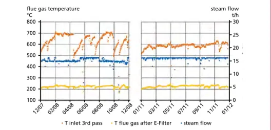
In reference A among others one SPG is installed at the rear wall of the third convective pass to clean the radiation pass 2 located upstream of the SPG. Temperature profile in Figure 3 show stable inlet temperatures at the third pass with installed SPGs in 2011.
Previously, values of 700 °C are reached regularly (see 2008), which led to a high cor- rosion rate in the final superheater. This plant A was shut down at the start of 2015, as it was replaced by a new waste-fired cogeneration plant (see reference E).
200 300 400 500 600 700 800
flue gas temperature
°C
100
12/07 02/08 04/08 06/08 08/08 10/08 12/08
30 25 20 15 10 5 0 01/11 03/11 05/11 07/11 09/11 11/11 01/12
steam flow T inlet 3rd pass T flue gas after E-Filter
steam flow t/h
Figure 4: Flue gas temperatures at outlet of radiation passes, after E-Filter and steam flow; on the left year 2008 (without SPGs), on the right year 2011 (with SPGs)
Waste Incineration
3.2. Reference B – replacing water canons
SPGs in reference B replaced existing water canons in radiation passes 2 and 3. Since installation of the SPGs, flue gas temperature at entrance to the fourth horizontal pass remains below 640 °C, and SH3 does not clog any more. The plant can achieve the desired continuous operating period even without additional manual boiler cleaning interventions, which was necessary twice a year before the installation of SPGs.
3.3. Reference C – replacing shower cleaning system
In this reference the third radiation pass contains a membrane evaporation wall, sub- dividing the pass into a left and a right half. In order to prevent excessive corrosion rate of superheater tubes, a maximum flue gas temperature of 700 °C should not be exceeded at the inlet of the horizontal pass.
In 2016, one SPG was installed at the lower part of the second radiation pass, to improve the cleaning of the radiation passes.
400 500 600 700 800 900
flue gas temperature
°C
29/03 28/04 29/05 28/06 29/07
300 250 200 150 100 50 0 25/03 24/04 25/05 24/06 25/07 T furnace T inlet horizontal pass T before SH2 T before SH1 steam flow
steam flow t/h
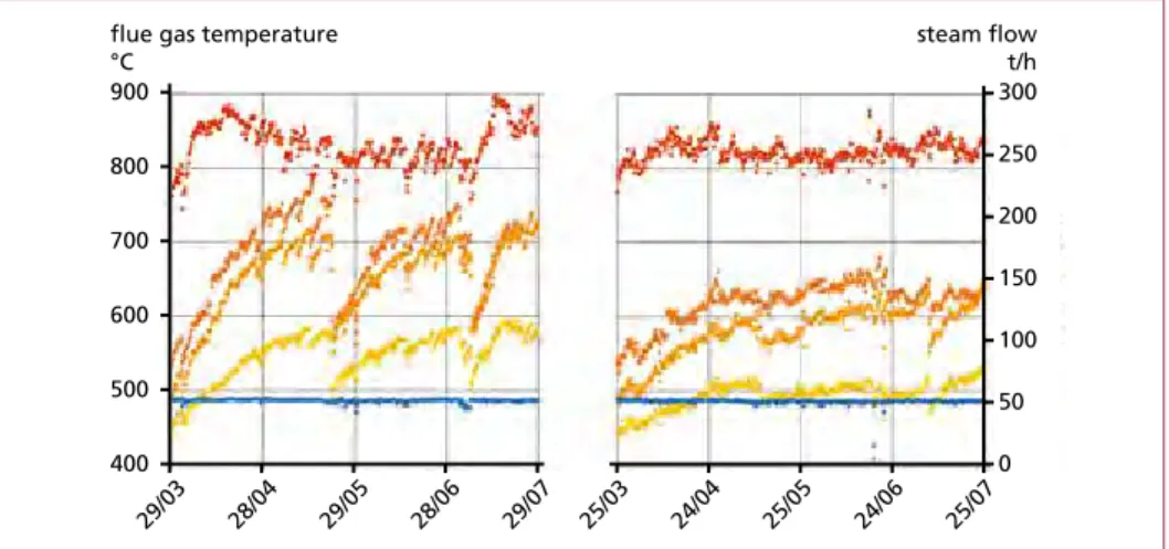
Figure 5: Temperature plots before and after SPG installation
In 2015 (Figure 5, left) the flue gas temperature at the inlet of the horizontal pass in- creased almost linearly, 7 °C per day, and reached the critical value of 700 °C less than one month after boiler start up. By using the Shower Cleaning System, the temperature could be kept around 700 °C for two to three weeks. In order to avoid a further increase of the temperature, a manual online boiler cleaning was required, which reduced the temperature to a similar value as after the maintenance stop. Thereafter, the periods until shower cleaning and manual boiler cleaning were again necessary, became shorter and shorter.
After the installation of the SPG (Figure 5, right), the flue gas temperature at the inlet of the horizontal pass increased in the first month to 600 °C but could then be kept within 600 to 650 °C for the rest of the four months operating period. The SPG was
Waste Incineration
commissioned one week after boiler start up. During week two and three the interval between Shock Pulses was four hours, during week four to five two hours and from week six onward one hour.
Further to the positive result of the reduced flue gas temperature and therefore lower corrosion rate at superheater bundles, the operator noticed positive effects for the ad- ditional manual online cleaning at the horizontal pass, which could be reduced from three to one intervention per 6-months-operation. Additionally, the sand blasting during the maintenance stop could be carried out faster because less material needed to be removed. Last but not least, the reduction of the flue gas temperature will allow overload operation of the boiler during periods with peak demand of the district hea- ting. A recent test proved to run a complete year without boiler stop, hence eliminating a previously planned shut down after six months.
3.4. Reference D – furnace pass and screen grid cleaning
In reference D a good cleaning effect at the grid tubes between first and second pass was reached due to the SPG installation. The cleaning effect is also clearly visible at walls of 1st pass (furnace) by reduced outlet temperatures at first pass. The boiler load was increased in 2008 by 15 %, therefore the plant operator encountered increased flue gas temperature, velocity and boiler fouling. After the SPG installation also the number of manual online cleanings within one traveling period was reduced to approximately one third.
3.5. Reference E – newbuilt with radiation pass Inconel cladding
In reference E SPGs for the three radiation passes were planned from the beginning.
The boiler was commissioned in 2015. It is a newbuilt boiler with Inconel cladding in the furnace pass. Experience from the last years showed the design values for radiation pass flue gas outlet temperature to be easily reached also after 8,000 hours (Table 2).
The three SPGs installed per boiler only create a Shock Pulse in average every 4.5 hours, which leads to low operating cost.
Reached mean value Measurement position after 8,000 h in 2016 °C
Flue gas temperature at inlet 2nd pass < 800 Flue gas temperature at inlet of horizontal pass < 600
Table 2:
Flue gas temperatures after 8,000 h operation
3.6. Reference F – 100 t/h boiler with clean radiation passes
This reference F is a nine-metre-wide boiler. Its radiation pass 2 and 3 are designed with evaporator panels covering part of the boiler pass. The cleaning effect of the units is good, the travelling period of the boiler was increased by one hundred percent after the installation. Before the retrofit intermediate manual boiler cleanings were required on a weekly basis. These SPGs are operated together with a Shower Cleaning System.
Waste Incineration
4. SPG radiation pass cleaning – different types for different radiation passes
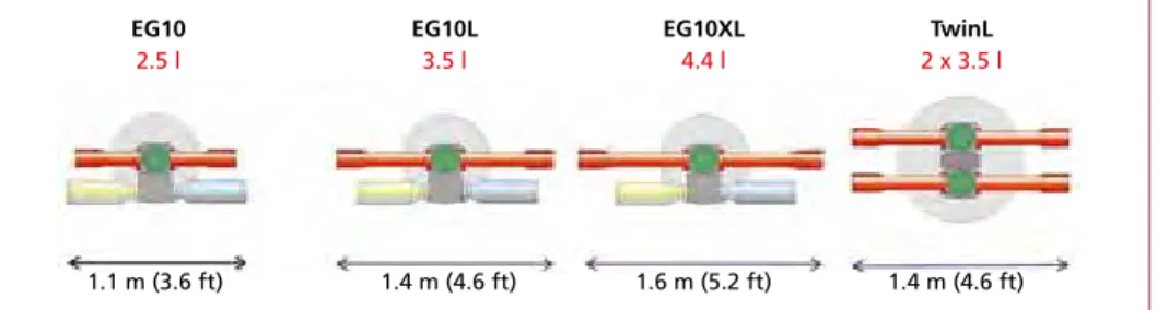
Nowadays, four different SPG types are available (Figure 6). The units differ by the amount of gas per one Shock Pulse. The following rules are based on the experience from radiation pass installations world wide. They can be taken as a rule of thumb for a first design proposal. For detailed planning, please reconfirm with the supplier or one of its partner companies.
Radiation passes without evaporator or superheater panels, i.e. only front wall, 2x side wall and rear wall as membrane walls, should be equipped as follows:
• pass width <= 6 m: 1 EG10L/pass
• pass width 6 to 8 m: 1 EG10XL/pass from one wall (side or front wall)
• pass width 8 to 12 m: 2 EG10XL/pass, from both sides, or 1 TwinL/pass from one side
• pass width 12 to 16 m: 2 TwinL/pass, from both side walls
EG10 EG10L EG10XL TwinL
2.5 l
1.1 m (3.6 ft) 1.4 m (4.6 ft) 1.6 m (5.2 ft) 1.4 m (4.6 ft)
3.5 l 4.4 l 2 x 3.5 l
Figure 6: Four different SPG types are available today
If evaporator or superheater panels are installed in the radiation pass, i.e. additional to front wall, 2x side wall and rear wall, it is more difficult to deliver rule of thumbs. A safe way would be to provide boiler drawings to the supplier or its partner companies for a detailed analysis. However, if the panels do not extend over the full length from front to rear wall, the following design guidelines can be used for preliminary planning:
• pass width <= 3 m and pitch of panels > 500 mm: 1 EG10L/pass
• pass width 3 to 6 m and pitch of panels > 500 mm: 1 EG10XL/pass
• pass width 6 to 10 m and pitch of panels > 500 mm: 2 EG10XL/pass, from both sides; or from rear wall; or 1 TwinL/pass from one wall
• pass width 10 to 14 m and pitch of panels > 500 mm: 2 TwinL/pass, from both side walls
For pass height larger than 15 metres or evaporator and superheater panels extending from the front to the rear wall, a detailed analysis must be performed. Also, if refractory or tiles are installed in the corresponding radiation pass, information about type, area and condition of the refractory are necessary.
Waste Incineration
5. Operating expenditures and benefits
The operation cost expenditures of the above described automated radiation pass cleaning system is mainly a function of the Shock Pulse Interval (SPI), i.e. how often the units are creating Shock Pulses. SPGs in radiation passes are operated on average with a SPI of two hours. Maintenance cost as well as gas consumption are related to these values. The units require a planned maintenance every 3,000 cycles. The shock pulses are created by means of combustion of methane or natural gas and oxygen.
The discharge nozzle is protected by permanent purge air (6 bar) and cooling air (e.g. 20 mbar).
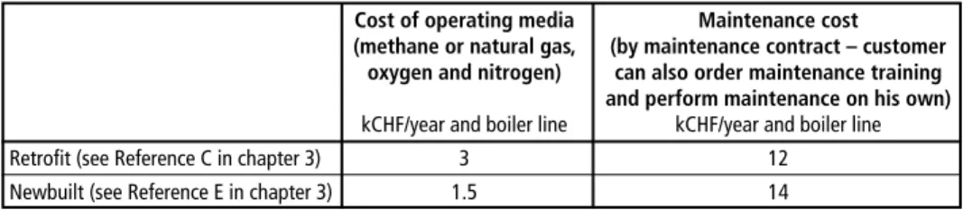
In Table 2 operating costs for two different references are shown. Hence customer in reference C has yearly operation cost for radiation pass cleaning of kCHF15 for one boiler. Customer in reference E cleans radiation passes of two boilers with yearly ope- ration cost of kCHF15.5 per line, i.e. total kCHF31, per year.
Table 3: Operating cost summary for a retrofit and a new built waste incineration plant Cost of operating media Maintenance cost (methane or natural gas, (by maintenance contract – customer
oxygen and nitrogen) can also order maintenance training and perform maintenance on his own) kCHF/year and boiler line kCHF/year and boiler line Retrofit (see Reference C in chapter 3) 3 12 Newbuilt (see Reference E in chapter 3) 1.5 14
Benefits of effective radiation pass cleaning are significant. In many cases, pay back times of few years have been reported. A big benefit is, that no additional water or steam is added to the flue gases, which might influence the convective pass fouling negatively.
In addition there is no klinker (risk to fall down) development in the radiation pas- ses – shorter downtime due to cleaning and less material to be dumped during boiler shut down for cleaning. Customers prolonged traveling period by up to one hundred percent, with less intermediate manual cleaning. Generally, lower and more stable flue gas temperatures at the outlet of the radiation passes were reached, contributing to overall smooth boiler operation and reduced corrosion rates.
6. References
[1] Born, M.; Beckmann, M.: Korrosionsschutzmaßnahmen in Abfallverbrennungsanlagen und Ersatzbrennstoff-Kraftwerken – Auswertung einer Betreiberbefragung. In: Thomé-Kozmiensky, K. J.; Beckmann, M. (Eds.): Energie aus Abfall, Band 9. Neuruppin: TK Verlag Karl Thomé- Kozmiensky, 2012, pp. 393-410
[2] Krüger, J.: Verhalten von Tropfen bei der Online-Kesselreinigung mit Wasser [3] Magel, G: Get to know the corrosions mechanism in waste-to-energy plants, 2017
[4] Steiner, C.; Ninck, K.: Boiler Cleaning with Shock Pulse Generators, POWER Magazin, Decem- ber 2016, Focus O&M pp.18-21, Online: http://www.powermag.com/boiler-cleaning-shock- pulse-generators/
Waste Incineration
Contact Person
Kaspar Ninck, M.Sc. Process Engineering ETH Explosion Power GmbH
Sales & Marketing Augustin-Keller-Straße 22 5600 Lenzburg
SWITZERLAND
Phone: 00 41 - 62 - 8 86 50 89
Email: kaspar.ninck@explosionpower.ch
Dorfstraße 51
D-16816 Nietwerder-Neuruppin
Phone: +49.3391-45.45-0 • Fax +49.3391-45.45-10
Waste Management
Rüdiger Margraf
Waste Incineration
Figure 7:
Rough scheme dry hydration CaO Dosing balance
H2O
Dry hydrator CaO
CaO Silo
Ca(OH)2 Ca(OH)2
Silo
towards lime dosing TIC
Several plants in Germany have been provided with this technology.
Figure 8 shows a plant, realised with a dry hydrator for a Ca(OH)2 production capacity of approximately 3 t/h.
Figure 8: RDF incineration plant EEW Premnitz / Germany As alternative there is the possibility to install the dry hydrator close to the additive
Verbrennungs-rost Gewebefilter Elektro- filter Sprüh-
trockner Kamin
Dampf- kessel MüllkranAufgabe-trichter
Müll- bunkerVerbrennungs-luftgebläseAufgabe-vorrichtungPlatten-wände TrogkettenfördererEntschlackung/
Ammoniak-Wasser- Eindüsung
Kessel- entaschung
AbgaswäscherDruckerhöhungs-gebläse Adsorbenssilo
Feuerraum Primär- luft
Figure 3:
Karl J. Thomé-Kozmiensky
Volume 2
WASTE MANAGEMENT
Luciano Pelloni
Waste Management Recycling Composting Fermentation Mechanical-Biological Treatment Energy Recovery from Waste Sewage Sludge Treatment
Thomé-Kozmiensky und PelloniWASTE MANAGEMENT
2
2
Thomé-Kozmiensky und Pelloni
Karl J. Thomé-Kozmiensky
Volume 3 Recycling and Recovery
WASTE MANAGEMENT
Stephanie Thiel
WASTE MANAGEMENTThomé-Kozmiensky und Thiel
3
, Thiel
5
2
Thomé-Kozmiensky und Pelloni
Volume 6 Waste-to-Energy
WASTE MANAGEMENT
Stephanie Thiel Karl J. Thomé-Kozmiensky
6
WASTE MANAGEMENTK. J. Thomé-Kozmiensky & S. Thiel
WASTE MANAGEMENT Volume 2
KARL J. THOMÉ-KOZMIENSKY STEPHANIE THIEL HRSG.
Copyright © 2011 TK Verlag Karl Thomé-Kozmiensky Alle Rechte vorbehalten.
Das Einspeisen der Daten in Netzwerke ist untersagt.
WASTE MANAGEMENT Volume 3
KARL J. THOMÉ-KOZMIENSKY STEPHANIE THIEL HRSG.
Copyright © 2011 TK Verlag Karl Thomé-KozmienskyAlle Rechte vorbehalten.
Das Einspeisen der Daten in Netzwerke ist untersagt.
Waste Management, Volume 2 – 7 • CD Waste Management, Volume 2 and 3
310.00 EUR
save 140.00 EUR
Package Price
Editors: Thomé-Kozmiensky (et.al.)
Waste Management, Volume 5 (2015) ISBN: 978-3-944310-22-0 90.00 EUR Waste Management, Volume 2 (2011) ISBN: 978-3-935317-69-6 CD includes translations in 50.00 EUR + CD Waste Management, Volume 2 ISBN: 978-3-935317-70-2 Polish and German
Waste Management, Volume 3 (2012) ISBN: 978-3-935317-83-2 CD includes translations in 50.00 EUR + CD Waste Management, Volume 3 ISBN: 978-3-935317-84-9 various languages
Waste Management, Volume 4 (2014) ISBN: 978-3-944310-15-2 50.00 EUR
Waste Management, Volume 6 (2016) ISBN: 978-3-944310-29-9 90.00 EUR Waste Management, Volume 7 (2017) ISBN: 978-3-944310-37-4 120.00 EUR
IRRC IRRC
2
Thomé-Kozmiensky und Pelloni
Volume 7 Waste-to-Energy
WASTE MANAGEMENT 7
WASTE MANAGEMENTK. J. Thomé-Kozmiensky et al.
Karl J. Thomé-Kozmiensky † Stephanie Thiel Elisabeth Thomé-Kozmiensky Franz Winter Dagmar Juchelková
TK Verlag GmbH
order now www. .de
hardc
over with coloured illustrations
Bibliografische Information der Deutschen Nationalbibliothek Die Deutsche Nationalbibliothek verzeichnet diese Publikation in der Deutschen Nationalbibliografie; detaillierte bibliografische Daten sind im Internet über http://dnb.dnb.de abrufbar
Thiel, S.; Thomé-Kozmiensky, E.; Winter, F.; Juchelková, D. (Eds.):
Waste Management, Volume 8 – Waste-to-Energy –
ISBN 978-3-944310-42-8 Thomé-Kozmiensky Verlag GmbH
Copyright: Elisabeth Thomé-Kozmiensky, M.Sc., Dr.-Ing. Stephanie Thiel All rights reserved
Publisher: Thomé-Kozmiensky Verlag GmbH • Neuruppin 2018 Editorial office: Dr.-Ing. Stephanie Thiel, Dr.-Ing. Olaf Holm,
Elisabeth Thomé-Kozmiensky, M.Sc.
Layout: Janin Burbott-Seidel, Ginette Teske, Roland Richter, Cordula Müller, Sarah Pietsch, Gabi Spiegel, Lena Bischkopf
Printing: Universal Medien GmbH, Munich
This work is protected by copyright. The rights founded by this, particularly those of translation, reprinting, lecturing, extraction of illustrations and tables, broadcasting, micro- filming or reproduction by other means and storing in a retrieval system, remain reserved, even for exploitation only of excerpts. Reproduction of this work or of part of this work, also in individual cases, is only permissible within the limits of the legal provisions of the copyright law of the Federal Republic of Germany from 9 September 1965 in the currently valid revision. There is a fundamental duty to pay for this. Infringements are subject to the penal provisions of the copyright law.
The repeating of commonly used names, trade names, goods descriptions etc. in this work does not permit, even without specific mention, the assumption that such names are to be considered free under the terms of the law concerning goods descriptions and trade mark protection and can thus be used by anyone.
Should reference be made in this work, directly or indirectly, to laws, regulations or guide- lines, e.g. DIN, VDI, VDE, VGB, or these are quoted from, then the publisher cannot ac- cept any guarantee for correctness, completeness or currency. It is recommended to refer to the complete regulations or guidelines in their currently valid versions if required for ones own work.