Flue Gas Cleaning Today
– Available Technologies and Latest Developments –
Christian Fuchs
1. Available flue gas cleaning technologies ...299
2. Description of the different technologies ...300
2.1. Dry sorption process ...300
2.2. Semidry process ...302
2.3. Wet process ...304
2.4. Hybrid process ...305
3. Today´s improvement on flue gas cleaning technologies ...307
4. History ...307
4.1. Components...308
4.2. Performance ...309
5. Availability and maintenance ...310
6. Return of invest ...310
7. Conclusion ...310 Many scientific approaches have been made in the past to determine the best flue gas cleaning technology.
An answer given was always depending on the legal requirements, the public opinion, the technical status of the period and maybe also depending on the persons interest giving the answer.
In other words, there is always a different or a new answer, depending on the year when you ask the question.
We try to summarize today´s situation on available flue gas cleaning technologies kno- wing that the corresponding BREF document is undergoing a revision at the moment.
1. Available flue gas cleaning technologies
In this presentation we will concentrate on the cleaning of acid gas components like SOx, HCl and HF of the flue gas only. Other pollutants like heavy metals, dioxins/furans or NOx require different technologies, which have to be combined with the acid gas cleaning or which have to be added as an additional cleaning stage.
Acid gas components are treated usually by adding caustic sorbents to the gas flow. There is a principal difference in cleaning technologies for flue gas differentiated into dry, semidry or wet procedures. In between is a significant number of hybrid-technologies, which combine these procedures to multistage cleaning systems. Multistage cleaning combines advantages of individual technologies to achieve an improved efficiency or economy.
As reactive sorbents available are different depending on the cleaning process:
• dry systems use either hydrated lime or sodium bicarbonate (actually sodium hy- drogen carbonate),
• semidry systems use quicklime,
• wet systems use caustic soda, quicklime or limestone.
2. Description of the different technologies 2.1. Dry sorption process
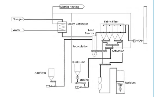
The dry sorption process based on hydrated lime has the architecture as described below – following the flue gas flow –:
• optional an evaporation cooler for the required conditioning of the flue gas to reach the required reaction temperature and to increase the humidity of the gas or alternatively a heat exchanger package to cool down the gas as required and thereby produce a significant amount of low pressure steam, which may be utilized (VapoLAB technology),
• a reactor to intensively mix sorbents and gas,
• a fabric filter to separate fly ash and sorbents from the flue gas flow,
• optional recirculation of the filter residues to enhance efficiency of the system,
• the ventilator to convey the flue gas from incineration to the stack,
• the stack,
• peripheral installations to support the process like storage and preparation of the sorbents, residues storage, compressed air preparation.
To treat acidic components of the flue gas additives like hydrated lime or sodium bicarbonate are injected into the flue gas and are thoroughly mixed by means of sta- tic or mechanical mixing devices, depending on the manufacturers technology. The efficiency of the reaction of sorbents with acid gas is strongly dependent of contact duration, sorbent distribution in the gas flow, reaction temperature and humidity. This is the reason why all variations of the dry sorption technology aim to optimize above mentioned conditions as much as possible.
An evaporation cooler is adjusting the temperature to the optimum for the reaction of hydrated lime, which is approx. 140 °C and represents the best compromise between efficiency and safe distance to the acid dew point, which mainly is depending on the HCl concentration of the gas.
As a secondary effect the relative humidity of the flue gas is increased by evaporation of water, which also has a very positive effect on the efficiency of the process. The presence of water (e.g. steam) is essential for the chemical reaction of acidic gas with hydrated lime.
Alternatively the flue gas may be cooled down to the reaction temperature using a heat exchanger to recover additional energy from the incineration to achieve a better thermal efficiency of the complete incineration system. The produced steam may be used in the boiler circuit, as city heating or utilized in the VapoLAB process, which is described later.
The influence of reaction time and particle distribution of additives in the flue gas is self-explaining. To reach better efficiencies there are various components used between injection of additives and the filter, which are static mixers, turbulence generators and mechanical reactors.
Recirculation of the fly ash and reaction salts captured in the fabric filter has a major effect on the efficiency of the dry sorption process. Not all injected sorbent had a chance to react in the time between its injection and the separation in the fabric filter. A certain amount of unused, still reactive sorbent is present in the filter ash. The unused amount of hydrated lime, in relation to the injected amount increases the stoichiometric ratio of the process above 1.0, which would be at one hundrd percent reaction. If all injected hydrated lime has reacted and there is no free lime in the residue, the stoichiometric ratio is 1.0. For dry systems the ratio is usually between two and three, depending on whether there is recirculation or not and whether there is additional humidification (water injection) of the residues while recirculating or not. To our experience the best stoichiometric ratio can be achieved by steam injection to the residues while recircu- lating, which has been measured with about 1.3.
Recirculation also has an additional positive effect: acid gas concentration resulting from a waste or RDF-incineration never is homogenous, there are always high con- centration peaks possible. Recirculating offers the benefit that the sheer mass of active sorbents in the flue gas flow is increased by factors – therefore the stability of such a system against peaks is by far higher than without recirculation.
In particular applications the use of sodium bicarbonate instead of hydrated lime as a sorbents may also be also advisable.
Here a cooling system is also required in most cases, in particular in existing incineration plants, to achieve a reaction temperature of about 170 to 180 °C. This requirement is not resulting from the use of sodium bicarbonate, but of other system requirements like the additional use of activated carbon, which limits the temperature to about 200 °C.
Flue gas
Water
Additives
Loop Reactor
Fabric Filter
Recirculation
Quick Lime
Slaking
Residues Activation Steam Generator
District Heating
Sodium bicarbonate is highly reactive, but requires in situ grinding of the granules to a very fine powder to achieve this high reactivity. Therefore grinding stations consisting of two or three special mills to be able to treat peaks and always have one mill available as being redundant for regular cleaning or unplanned downtimes.
When injecting the freshly ground powder into the hot flue gas actually the sodium bicarbonate is created out of sodium hydrogen carbonate by losing water.
Figure 1: Process diagram dry sorption, here: VapoLAB
2.2. Semidry process
The semidry process uses quicklime as sorbent, which is cheaper than the hydrated lime and also offer additional thirty percent reactive material, because it does not contain any water. The slaking may happen locally in an offline process to prepare lime milk, consisting of slaked lime and water.
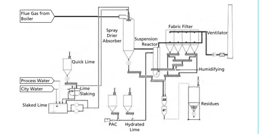
The semidry sorption process based on quicklime has the architecture as described below (following the flue gas flow):
• a spray drier absorber to condition the flue gas to the optimum reaction temperature of about 140 °C and simultaneously inject lime milk to reduce the acid components of the flue gas in a first stage,
• a reactor to intensively mix sorbents and gas and add additional sorbents like PAC (pulverized activated carbon) and hydrated lime to reduce acid components in a second stage,
• a fabric filter to separate fly ash and sorbents from the flue gas flow,
• optional recirculation of the filter residues to enhance efficiency of the system,
• the ventilator to convey the flue gas from incineration to the stack,
• the stack,
• peripheral Installations to support the process like storage and preparation of the sorbents, residues storage, compressed air preparation.
All conditions for the reaction already described in the chapter dry sorption are fully valid for the semidry sorption as well. These conditions are residence time, temperature, humidity and recirculation.
The main difference between dry sorption and semidry sorption is the sorbent being a suspension instead of a powder, which evaporates by increasing the humidity of the flue gas locally at the additive surface. Molecular movements of acid gas to prepare the reaction with lime are enhanced in these conditions, reaction in particular with SOx, HF and HCl are improved. When completely dried the sorbents still reacts with acid components in a normal dry sorption. As a general rule semidry systems are very effective because they have one additional reactor to allow for higher inlet concentra- tions of acid components.
Dimensioning of the absorber has to allow for a complete drying of the suspension to form dry particles. Usually this is achieved with a residence time of about twenty seconds, which also is additional reaction time.
The absorber usually is operated at about 140 °C to ensure the safe distance to the acid dew point.
Volatile heavy metals and dioxins/furans are captured efficiently both at dry and se- midry systems by injecting PAC.
Process Water City Water Flue Gas from Boiler
Slaked Lime
Quick Lime
Lime Slaking
Spray Drier Absorber
PAC Hydrated Lime
Fabric Filter
Ventilator
Residues Humidifying Suspension
Reactor
Figure 2: Process diagram semidry sorption (SemiSecoLAB)
2.3. Wet process
The wet process uses quicklime, caustic soda, ammonia or limestone as sorbent, depending on the application. Incinerations for waste and RDF usually operate with quicklime, since this reagent is a good compromise between performance, additional effort to prepare the sorbent and price. Incinerations for hazardous waste or sewage sludge use caustic soda, because these plants require a high performance and they are usually quite small, which means the consumption of costly caustic soda is low. Power plants, which consume tons of sorbent per hour for desulphurization, use limestone only, because this is widely available at low costs. A very special application is the use of ammonia as agent producing fertilizer instead of residues, which have to be disposed.
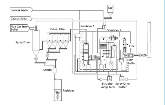
The wet process has the architecture as described below (following the flue gas flow):
• optional dust separation with electrostatic precipitation,
• a spray drier to evaporate the reaction salt suspension of the scrubber bleed,
• a fabric filter,
• a quench to condition the flue gas to saturation temperature, usually integrated in the scrubber,
• the first scrubber, mainly operating to treat strong acid gas like HF and HCl,
• droplet separators,
• the second scrubber, mainly operating to treat SO2,
• droplet separators,
• optional the Electrodynamic Venturi (EDV) to minimize the droplets passing the system,
• the ventilator to convey the flue gas from incineration to the stack,
• the stack,
• peripheral installations to support the process like storage and preparation of the sorbents, residue preparation, residues storage, compressed air preparation. In particular residue handling is involving extensive treatments like evaporation of scrubber bleed or waste water treatment,
• optional a gas/gas heat exchanger or a heat transfer system.
The flue gas entering the flue gas cleaning installation are usually quenched to satura- tion temperature (about 60 °C) subsequent to a dedusting facility like an Electrostatic Precipitator or, in case the reaction salts are evaporated, a spray drier and a fabric filter.
The first scrubber treats halogen acids and SO3, and is operated at a low pH-value. The droplet separator ensures a hydraulic separation between the two scrubbers. The second scrubber is operated at a relatively neutral pH value to mainly catch SO2. Finally follows a second droplet separator and, if required to reach very low particulate emissions, an additional EDV to minimize the droplets going to the Ventilator and stack.
Both scrubbers are controlled by monitoring and maintaining the pH value, if the value is decreasing, the continuous bleed is increased.
The bleed is either evaporated in a spray drier as part of the flue gas cleaning installa- tion or in an evaporation tower, which is extremely energy consuming. Alternatively a waste water treatment is possible with neutralization, separation of heavy metals and Mercury involving numerous pumps, pipings, measurements and vessels as well as a separate control system.
Separation of heavy metals, mercury and dioxins/furans can be integrated in the scrub- bing process and does not require additional process steps, just storage and injecting of an additional adsorbents, mainly PAC.
The wet process offers the benefit of a nearly complete chemical reaction of acid gas components and sorbents, stoichiometric ratio is near 1.0. This offers the most eco- nomic use of sorbents and also produces the minimum possible amount of residues.
Process Water Caustic Soda Flue Gas from Boiler
Spray Drier
Fabric Filter Scrubber 2
Scrubber 1
Residues
PAC
Sender
EDV
EDV Buffer
Spray Drier Buffer Scrubber Sump Tank
Figure 3: Process diagram wet process
2.4. Hybrid process
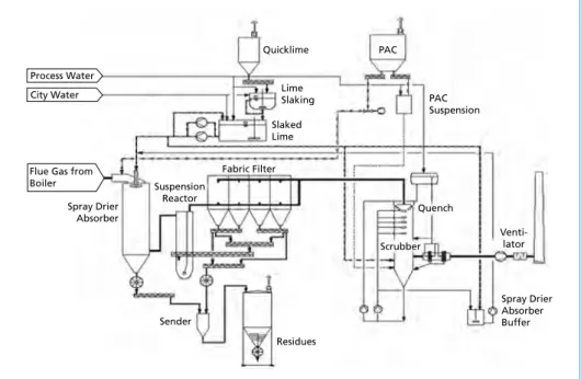
The hybrid process is mainly a combination of above technologies. Here we describe as an example the combination of semidry and wet process.
This particular hybrid process has the architecture as described below (following the flue gas flow):
• a spray drier absorber to condition the flue gas to the optimum reaction temperature of about 140 °C and simultaneously inject lime milk to reduce the acid components of the flue gas in a first stage. Also the scrubber bleed is evaporated here,
• optional a reactor to intensively mix sorbents and gas and add additional sorbents like PAC (pulverized activated carbon) and hydrated lime to reduce acid compo- nents in a second stage,
• a fabric filter to separate fly ash and sorbents from the flue gas flow,
• optional recirculation of the filter residues to enhance efficiency of the system,
• a quench to condition the flue gas to saturation temperature, usually integrated in the scrubber,
• the scrubber as a third cleaning stage,
• droplet separators,
• the ventilator to convey the flue gas from incineration to the stack,
• the stack,
• peripheral installations to support the process like storage and preparation of the sorbents, residue preparation, residues storage, compressed air preparation. In par- ticular residue handling is involving extensive treatments like neutralization and evaporation of scrubber bleed.
This particular hybrid process combines two powerful technologies to ensure very low emissions or to treat high concentrations of acid gas components.
Combining the powerful semidry process and the efficient scrubber forms an economic compromise of high performance characteristics at economic operating costs.
Figure 4: Process diagram hybrid process
Process Water
Quicklime
City Water Lime
Slaking Slaked Lime
Scrubber Quench
Spray Drier Absorber Buffer Spray Drier
Absorber
Suspension Reactor Flue Gas from
Boiler
Venti- lator Fabric Filter
PAC
PAC Suspension
Sender
Residues
3. Today´s improvement on flue gas cleaning technologies
Comparing and selecting flue gas cleaning technologies can only be complete under consideration of many conditions, which may be different at all possible locations.
Principally every installation will be different, which explains also the variety of tech- nologies available.
For example, an existing installation with grown infrastructure, limited space available and an existing permit describing certain emissions will surely build different compared with a new installation on green field, which is under planning only. Also availability, investment costs and operating costs as well as residues have to be considered.
Nevertheless, all flue gas cleaning installations have to fulfill one single requirement:
• low investment,
• low operation cost,
• low maintenance,
• low emission.
In the past the simple criteria low was difficult to fulfill in all above aspects. This is the explanation for the different approaches to clean flue gas.
In future this may be more simple:
The VapoLAB technology is able to fulfil all these tasks for most applications.
It is a dry/semidry technology which based on the simple dry sorption process. The new approach is that a standard dry sorption process consisting of (optional) evaporation cooler, loop reactor, fabric filter and recirculation with humidification is upgraded by the use of steam instead of water for the Humidification.
This modification dramatically improves the characteristics of the dry sorption tech- nology and boosts both performance and reliability.
4. History
Dry sorption technology used to be requested in the past by many investors due to the attractive commercial conditions, low investment costs and low requirements for space and maintenance.
On the other side the requirements on performance were raised to meet even the worst possible fuels like RDF or sewage sludge.
The R&D departments of the suppliers for flue gas cleaning systems have surely been active and developing today´s variety of dry systems.
We have been looking for new ways of combining all benefits of using only gas as a activator instead of using liquids and gas to be introduced to the recirculation ash.
From all experiences from other companies as well as our own we knew about the limitations you can achieve by using water.
Gas on the contrary to water does not form any paste or slurry with the ash, which re- mains powdery at all times. Our R&D department has proven this in our own laboratory.
A full scale trial was initiated in Bremen, Germany and a first industrial installation was finished in Teesside, England.
At the moment two installations are in operation and nine more under construction.
Obviously the demand for low invest and high performance flue gas cleaning techno- logy is very strong.
Below we present the technology and some results we achieved.
4.1. Components
The performance of a dry sorption system strongly depends on recirculation and reac- tivation. The VapoLAB technology is not different, but better. Filter ash is recycled via a twin screw mixer, which is able to intensively mix the recycled ash with the injected steam to enhance the contact and the contact time between ash and steam. After a certain residence time the recirculate is released to the feed screw and fed back to the flue gas in the reactor before filtration.
Thus we have the same and similar proven components for steam activation compared to water activation, but without the disadvantages.
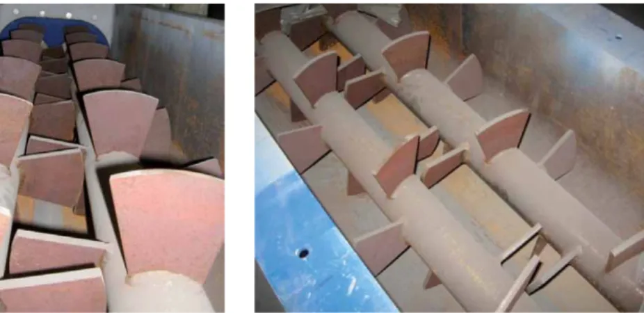
The arrangement of the recirculation mixer may be similar to the drawing below, which shows the arrangement in an existing installation.
Inside the mixer two screws with paddles take care to assure the correct residence time of the ash for activation with steam. We usually aim to keep a minimum ash level in the mixer to ensure the best reaction.
bucket elevator
vent pipe
distribution conveyor
steam manifold
activation screw Figure 5:
Mixer with steam activation
Figure 6 and 7: Mixer inside
The mixer itself is of sturdy design, made to reach long operational periods and reliable operation.
4.2. Performance
How is the effect of steam to the stoichiometric factor (lime consumption), how can lower emissions be reached without increasing lime consumption?
The answer is using steam for reactivation. Below are some diagrams showing direct- ly the effect of steam to the process. These data have been sampled in our reference installation Teesside in England. The first picture displays the effect of steam to the emissions values. It is a collection of 45 daily average values, where after 32 days the steam is cut off without changing the lime feed rate. This results in an increase of the emissions of SO2 from approx. 18 mg/Nm³ to 40 mg/Nm³.
If the emissions are not changed and are stabilized there is a different effect noticeable:
the lime consumption goes down and the stoichiometric ration is improved The dia- gram below again is a plot of 45 days, where after 32 days the steam is switched off. The result is an increase in lime consumption from 130 kg/h to 220 kg/h. in other words, our technology improved the lime consumption of this existing plant from originally 260 kg/h from the original supplier to 220 kg/h with our recirculation system and finally down to 130 kg/h with additional steam injection. This efficiency is comparable with the performance of bicarbonate or with wet scrubbing systems.
80 60 40 20 0
1 3 5 7 9 11 13 15 17 19 21 23 25 27 29 31 33 35 37 39 41 43 45
Figure 8:
Steam Effect on SO2 emissions
In the end the results of a long term operation show, that a consumption of about eleven kilogram lime per ton of incinerated waste is an average which can be achieved at an average municipal waste while maintaining a stable operation at full availability.
5. Availability and maintenance
The theoretical advantages of a technology using only gas to reactivate the recycled additives is self-explaining: the absence of any liquid makes it impossible to form pastes and slurries. The results in practice show, that the theory works. Two years operation in Teesside show, that no conditions appear which reduce the function or the availa- bility out of the mixing and the recirculation process itself. Maintenance is reduced to occasional cleaning of the reactor venting.
6. Return of invest
Our customer in England saves about 2,000 tons of lime per year, which reduce the ad- ditive costs, the disposal costs and the maintenance costs as well. In case of our English installation the existing flue gas cleaning technology was upgraded by the described system and provides a return of invest in less than two years.
When investing in a new installation, the system is of comparable costs as standard dry sorption technologies, but by far more effective and economic.
7. Conclusion
The range of available flue gas cleaning systems spreads from simple systems like the dry sorption to complex multistage wet scrubbing systems, which even may be combined to form hybrides to fulfill very particular economic or technical conditions.
Within the comparism of the different systems the dry sorption systems have gained in importance. They are attractive in invest cost, the performance has increased dra- matically during the recent years and in particular the VapoLAB process is very thrifty with costly additives.
400 300 200 100 0
1 4 7 10 13 16 19 22 25 28 31 34 37 40 43
Figure 9:
Steam Effect on lime consumption