Selective Flue Gas Cooling and TWIN-NO
x▪
▪
Selective Cooling optimizes flue gas temperatures for the SNCR process at the injection positions. NOx reduction rates are improved and the consumption of reagents is reduced.
The TWIN-NOx® process produces excellent results by combining the advantages of the reagents ammonia water and urea solution.
Combining Selective Cooling and TWIN-NOx®
Mehldau & Steinfath Umwelttechnik GmbH, Alfredstr. 279, 45133 Essen • Tel. +49 201 43783-0
Level3 Cooling Water Temp.
Measurement Level 2
Level 1 Mixing and Metering
Module FC
FC Compr . Air
Water Reagent
original SNCR
Extension for future NO limitsX
▪
▪
▪
▪
▪
▪
Low investment costs
Reduced consumption of reagents Easy retrofitting
High availability
Improved NOx reduction rates Safe compliance
with new EU standards
Optical temperature measurement
Flue Gas T
Complying with the New EU NO
xEmission Standards
– Combining Advanced SNCR Technologies –
Bernd von der Heide
1. Future NOX emission limits for combustion plants ...623
2. Retrofitting or refurbishing of existing SNCR systems ...628
3. Adaptation to changed operating conditions ...630
4. Results and practical experiences ...632
5. Comparing SCR to SCNR under energy and environmental aspects ....633
6. Summary and outlook ...634
7. Literature ...635 The valid emission limits in the EU, for example NOx emissions of waste-to-energy plants and combustion plants fired with other fuels like coal, oil, biomass, etc. have to be adjusted from time to time reflecting the progress of technical developments as well as environmental concerns.
A technology which is best suited to reach a high level of environmental protection by keeping a reasonable cost/benefit ratio is called Best Available Technology (BAT).
This paper shows how the improvements that have been achieved with the technology of Selective Non-Catalytic NOx Reduction (SNCR) can be applied not only in new but also in existing combustion plants which have been operating for many years with an older DeNOX system.
1. Future NO
xemission limits for combustion plants
BREF is the abbreviation for Best Available Technique REFerence Document, or in short: BAT reference Document. In German a BVT leaflet defines the Best Available Technique corresponding to BREF.
The Final Draft of the BVT leaflet for waste-to-energy plants defines the NOx emission requirements which are shown in Table 1.
When the first SNCR plants were put into operation in the 80s of the last century, the NOx limits of < 200 mg/Nm³ in accordance with the German Federal Emission Control Act (17. BImSchV) could reliably be complied with although the technical configuration
Flue Gas T was relatively simple. This was owed to the fact that the combustion plants were mostly operated at full load. Therefore, the variation of flue gas temperatures in the first boiler
Emissions Unit New plants Existing plants NOx
mg/Nm³
< 120 < 150
CO < 50 < 50
NH3 slip < 10 < 10
Table 1: Final draft of the BVT leaflet for Waste-to-Energy plants
pass stayed within an acceptable range.
Furthermore, ammonia slip was not of major concern at that time. According to TA Luft, another German regulation, the limit was < 30 mg/Nm³ so that an SNCR plant equipped with only one injection level was sufficient to fulfil the require- ments imposed by the regulators.
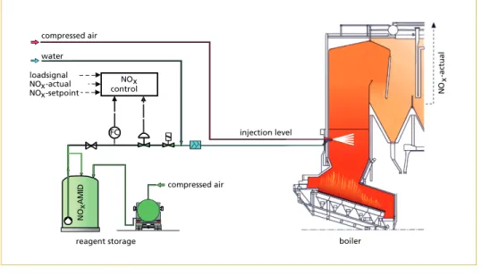
Figure 1 shows the concept and the functions of a typical first generation SNCR plant with urea solution as reagent which used to be operated in combustion plants according to 17. BlmSchV, reaching a NOx reduction of up to 60 %. Depending on the requirements the SNCR plants are equipped with one or two injection levels.
compressed air water
controlNOx loadsignal
NO -actualx NO -setpointx
FC injection level
compressed air
NOxAMID NO
-actual x
reagent storage boiler
Figure 1: Process diagram of a first generation SNCR plant
Source: von der Heide, B.: Ist das SNCR-Verfahren noch Stand der Technik? In: Thomé-Kozmiensky, K. J.; Beckmann, M. (Eds.):
Energie aus Abfall, Band 4. Neuruppin: TK Verlag Karl Thomé-Kozmiensky, 2008, pp. 275-293
In response to load changes and/or to the flue gas temperatures the injection levels can be switched to follow the average flue gas temperatures in the injection levels.
In order to follow major temperature variations and imbalances which typically arise during operation, to reduce NH3 slip and to optimize the consumption of reagent, two injection levels proved to be most effective in waste-to-energy plants which were equipped in the 1990s in accordance with the 17. BlmSchV (Figure 2). These two in- jection levels are switched on or off depending on the average temperatures measured with thermocouples at the boiler roof in the first flue gas path.
Flue Gas T
Figure 2: Changing injection levels following temperature imbalances
Under favourable operating conditions, when homogeneous fuel is used and the boiler is operated at constant load, NOx clean gas values of < 150 mg/Nm³ can be achieved with this concept. However, imbalances of the flue gas temperatures and the flue gas flow may affect NH3 slip and consumption of reagent. In case major temperature im- balances are found between the front and the rear walls of the furnace activating only one half of the injection level – front or rear – is a very successful solution.
level 2
level 1 temperature
too hot temperature
too cold temp. optimum
injection with one or two levels resp. changing from level 1 to level 2 level 2 in operation
level 1 not in operation
level 2
level 1
injection levels 1 and 2 front level 1 in operation rear level 2 in operation (changing of single lances) lance in operation lance not in operation
temperature too hot temperature
too cold temp. optimum
Advantages of changing of indiviual lances and/or injecting of cooling water versus
standard SNCR system
• higher efficiency
• lower NOx emission
• NH -slip < 10 mg/Nm3 3
• reduced reagent consumption
• lower CO emissions
changing of individual lances changing of individual lances
with selective flue gas cooling
Figure 3: Changing of individual lances with and without selective cooling versus standard SNCR However, the concepts described above are not sufficient for modern plants which are operated in accordance with the current BREF standards.
The next step in the technological progress was that individual lances or groups of lances were activated or deactivated in order to make sure for any location that the reagent is
Flue Gas T always injected into the range of the temperature window where NOx reduction, NH3 slip and consumption of reagent reach their optimum (Figure 3).
600 700 800 900 1,000 1,100 1,200 1,300
COO2 SO2 SO3
NOX
H2
Urea/NOX
(NSR)
0 20 40 60 80 100
10 0 20 30 40 50 60
"A" - optimum temperature for SNCR alone (low ammonia-slip)
NH3-slip mg/Nm³ NOx-reduction
%
"A"
"B"
NH3
NOx
temperature °C range for NO /NH -X 3
optimised operation
range for SNCR- and SCR-operation
"B" - optimum temperature for SNCR and SCR (high ammonia-slip)
Figure 4:
Influence of the flue gas com- position on the temperature window
For optimum performance both the flue gas composition and the flue gas temperatures are essential for controlling the SNCR process. Where the optimal temperature window for SNCR lies depends very much on the flue gas composition (Figure 4). This means, for example, that CO shifts the temperature window towards lower temperatures, while SO2 has the contrary effect. The optimal temperature window for waste-to-energy is located between 980 to 1,030 °C, for fluidized bed boilers where CO is generally high it is below 900 °C, and for furnaces with a high SO2 content in the flue gases it is up to 1,050 °C. Depending on the desired performance of the SNCR one of the following temperature measurement methods could be applied:
• Thermocouples are very sensitive to the influence of heat radiation from the furnace, as well as to cold radiation from the boiler walls and the heat exchangers. In the past they were installed in SNCR plants which had to comply with 17. BlmSchV only, but due to the described limitations this method does not meet the requirements of more stringent NOx limits.
• The measurements with suction pyrometers are quite accurate and are mainly used for manual temperature measurements to verify the continuous measurement sys- tems. They are not suitable for continuous measurements since their handling is time-consuming.
• Broad experience has been gathered with acoustic gas temperature measurement systems which have proven to be suitable for the most demanding applications. This method is therefore recommended where NOx emission values < 100 mg/Nm³ and NH3 slip < 10 mg/Nm³ have to be guaranteed.
Flue Gas T
• Since several years spectral pyrometers have been put into operation increasingly.
The results achieved with this optical method show that – in relation to acoustic measurements – comparable degrees of NOx reduction can be obtained at lower cost.
Figure 5: Methods of contact-free temperature measurement
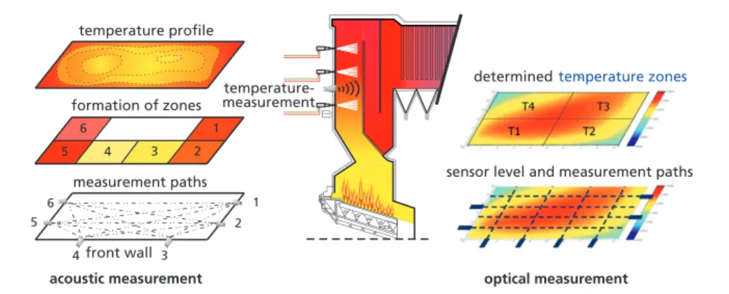
• Both methods, the optical and acoustical temperature measurement, have advan- tages and disadvantages (Figure 5 and 6): During the acoustic measurement each transceiver at the boiler wall communicates in turns with all the other transceivers.
Thus, a multitude of temperature paths is formed which provide a high resolution.
• In contrast, each spectral pyrometer measures one path only which results in a lower resolution. The advantage of this method is that it provides sufficiently accurate temperature measurements even in areas which are otherwise difficult to access, for example between the heat exchangers and individual injection lances.
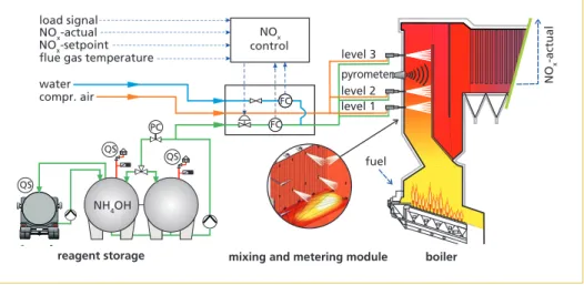
At the waste-to-energy plant Wijster in the Netherlands, three SCR units of the plant were shut down and replaced by SNCR systems. In response to the ambitious require- ments (NOx reduction from approximately 330 to 350 mg/Nm³ to < 60 mg/Nm³ and an NH3 slip < 10 mg/Nm³) three injection levels with six lances each were installed.
In this concept each lance is activated individually depending on zone temperatures.
sensor level and measurement paths determinedtemperature zones temperature-
measurement
2 1 3 4 5
6
2 3
5 6
4front wall measurement paths formation of zones
temperature profile
1
acoustic measurement optical measurement
Figure 6:
Methods of contract-free tempe- rature measurement – acoustic (left), optical (right)
Flue Gas T After determining the temperature profile, it is divided into sections and can be assigned to a certain lance or group of lances which can then be activated depending on the flue gas temperatures. Even when there are sudden changes in the flue gas temperatures this method ensures that the reagent is injected into those areas where optimum results regarding NOx reduction, NH3 slip and consumption of reagent can be achieved.
NOx-actual
mixing and metering module
reagent storage boiler
NH4OH NH4OH
F NOx control load signal
NOx-actual NOx-setpoint
flue gas temperature level 3
level 1 level 2 compr. air
water
NH4OH
QS QS QS
PC
FC FC
pyrometer
fuel
Figure 7: SNCR with individual change of lances in three levels – Waste-to-Energy plant The results that were measured in continuous operation of several combustion plants show that NOx clean gas values of < 100 mg/Nm³ and an NH3 slip of < 10 mg/Nm³ can be guaranteed and even noticeably better results are possible under favourable operating conditions.
2. Retrofitting or refurbishing of existing SNCR systems
Older SNCR plants which have been operated successfully for 20 years or more, have a limited ability to meet the recent requirements or cannot meet them at all. Consid- ering the future NOx limits of < 100 mg/Nm³, NH3 slip < 5 mg/Nm³ and minimized consumption of reagent, these plants need to be refurbished.
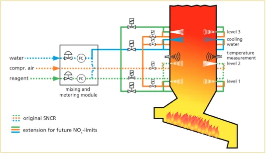
Measures for refurbishing include the extension of the system to three injection levels, changing of individual lances and acoustic or optical pyrometers for the continuous measurement of the flue gas temperatures (Figure 8).
Depending on age and condition of the SNCR plant it may be feasible to include the additionally needed armatures in the existing mixing and metering modules. In most cases, however, this cannot be recommended, and often it is not possible either since the additional components need more space than is available in the mixing and metering modules of the simple types of first generation SNCR. If space in the modules is too restricted, this may hinder the necessary access for maintenance works and should therefore be taken into consideration as well.
Flue Gas T
Sometimes the limited space in the boiler house does not allow for the installation of a bigger mixing and metering module. In such a case a possible solution may be to install the additional instruments between the module and the injection lances directly on the boiler walls.
Figure 8: SNCR process – flow diagram before and after retrofitting
Figure 9:
Mixing and metering modules before and after retrofitting – original (left), refurbished (right)
Figure 10: Installation of additional equipment on the boiler walls
Even if the further use of the existing components (e. g. control valves, pressure retaining valves, ball valves etc.) is intend- ed, in many cases, it makes more sense to use new and larger cabinets and to com- plement them with new armatures. Mostly it is easier and more cost-efficient to set up the mixing and metering modules in bigger new cabinets in the workshop than to use the old smaller cabinets for the mounting of additional parts at site (Figure 9 and 10).
level 3 cooling water t emperature measurement level 2
level 1 mixing and
metering module FC
FC compr. air
water
reagent
original SNCR
extension for future NOx-limits
Flue Gas T
3. Adaptation to changed operating conditions
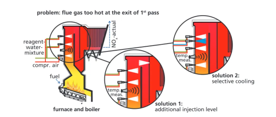
Many waste-to-energy plants are operated at a capacity range which is higher than originally designed for. As a result the flue gas temperatures are higher than they were at the time when the plant was first put into operation. Consequently, the optimum temperature range for the SNCR process is often shifted to the second pass, especially at the end of the service interval and when ammonia water is used as the reagent. With the rising temperatures the reagent is increasingly burnt to NOx. The required NOx reduction can, therefore, in many cases only be achieved with a higher consumption of reagent and an increased ammonia slip (Figure 11).
fuel
NOx-actual compr. air
temp.
meas.
problem: flue gas too hot at the exit of 1st pass
solution 1:
additional injection level solution 2:
selective cooling
furnace and boiler reagent-
water- mixture
temp.
meas.
Figure 11: Technical solutions when flue gas temperatures are too hot
A possible solution is the installation of additional injection lances in the second pass which can be activated when the flue gas temperatures are too high. Should this not be possible, the same effect can be realized by injecting additional cooling water beneath the hottest lances of the highest injection level (Figure 12).
T0 flue gas temperature > 1,050 °C reaction temperature < 1,050 °C
cooling water reagent/
water mixture T1
urea solution cooling water
compressed air burners
injection
agam
T0 T1
T1
flue gas
Figure 12: Principle of selective cooling
Flue Gas T
Relevant results and experiences with this method, protected by patent as Selective Cooling, showed in many cases a significant improvement of NOx reduction and the consumption of reagent. Selective Cooling cools the flue gases locally and temporarily. The major ad- vantage of this method is that even at high boiler loads and flue gas temperatures, i. e. the complete load range, by changing individual lances injection is possible in the areas with optimum flue gas temperatures which are free of installations at the end of the furnace.
This means that costly modifications of the heat-exchangers can be avoided.
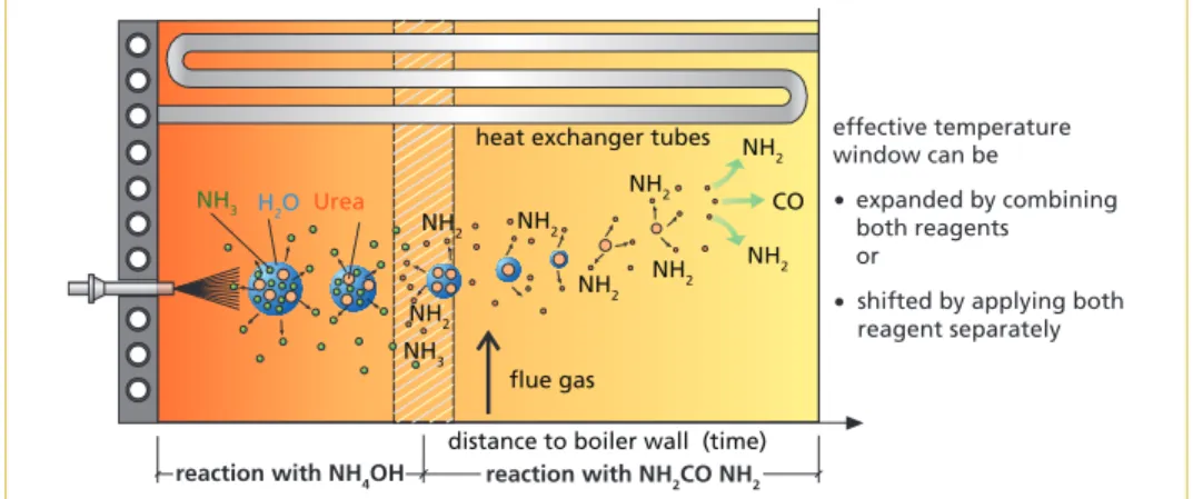
Another method which has performed well is the TWIN-NOx process which combines the benefits of both reagents, urea and ammonia, in such a way that the effective tem- perature window is practically expanded (Figure 13 and 14).
reaction with NH4OH reaction with NH2CO NH2 distance to boiler wall (time) NH2 NH2
NH2 NH2
NH2 NH3 NH3
NH2 NH2
NH2 CO H2O Urea
flue gas
heat exchanger tubes effective temperature window can be
expanded by combining both reagents or
shifted by applying both reagent separately
•
•
Figure 13: Expansion of temperature window – combination of urea solution and ammonia water This means that the highly volatile ammonia water is applied at low loads where the ammonia is released immediately and can react with NOx. When using urea solution, the reaction is delayed because the NOx reduction can only begin after the process water has evaporated and the urea molecules have been decomposed to NH2 radicals and CO.
Figure 14 shows a simplified process diagram of an SNCR plant which can be operated al- ternatively with urea solution or ammonia water as well as with a mixture of both reagents.
NH4OH
mixing and metering module
ammonia water urea solution
compr.
air water
FC FC
FC
NOx control load signal
NO actualx NO setpointx flue gas temp.
level 3
level 1 level 2 temp.
meas.
boiler NH4OH
NOxAMID
Figure 14: Process diagram of the TWIN-NO process
Flue Gas T
4. Results and practical experiences
The results and experiences with SNCR systems which have been retrofitted show that the future emission limits for NOx and ammonia can be met reliably.
0 2 4 6 8 10 12 14 16 18 20 22 24 26 28 30 32
0 10 20 30 40 50 60 70 80 90 100 110 120 130 140 150 160
12. Okt 17 20. Okt 17 28. Okt 17 05. Nov 17 NOx actual NOx limit NH3 actual NH3 limit Nitrogen Oxides (NOx)
mg/Nm³ Ammonia (NH3)
mg/Nm3
Figure 15: Emission levels – IKW Rüdersdorf
Source: IKW Rüdersdorf GmbH: IKW Rüdersdorf – Emissionswerte. Retrieved: November 12, 2017; from: http://ikw-rüdersdorf.
de/emissionswerte.htm
0 2 4 6 8 10 12 14 16 18 20 22 24 26 28 30 32
0 10 20 30 40 50 60 70 80 90 100 110 120 130 140 150 160
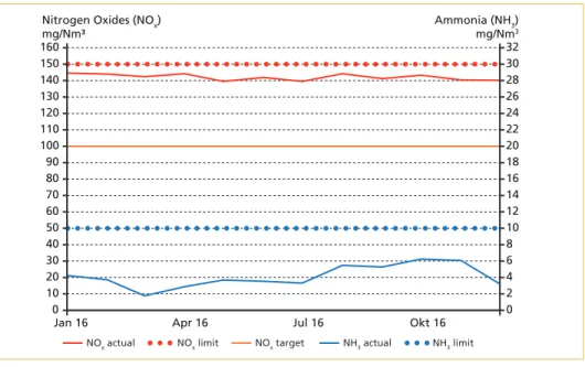
Jan 16 Apr 16 Jul 16 Okt 16
NOx actual NOx limit NOx target NH3 actual NH3 limit Nitrogen Oxides (NOx)
mg/Nm³
Ammonia (NH3) mg/Nm3
Figure 16: Emission levels – Waste-to Energy plant Salzbergen
Source: SRS EcoTherm GmbH: Emissionswerte der MVA Salzbergen 2016. Retrieved: November 12, 2017; from: http://www.
Flue Gas T
The combustion plants in Salzbergen (municipal waste) and Rüdersdorf (refuse de- rived fuels) have been retrofitted and safely comply with the present regulations of NOx < 150 mg/Nm³ and NH3 < 5 mg/Nm³, as can be seen from the results shown in Figure 15 and Figure 16.
These and other plants, which are presently being retrofitted, require relatively little efforts in order to enable them to guarantee NOx levels < 100 mg/Nm³.
5. Comparing SCR to SCNR under energy and environmental aspects
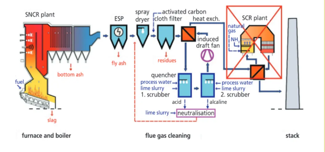
In the waste-to-energy plant in Wijster, Netherlands, the existing SCR plant was re- placed with an SNCR system in order to save operating costs (Figure 17). The SCR was installed downstream a wet flue gas cleaning system. The pressure drop across the heat-exchangers, the mixer, the flue gas ducts, and the catalyst elements amounted to approximately 25 mbar. To overcome the pressure drop, a blower with an electrical consumption of 250 kW per combustion line was required, whereas this additional energy is not needed in an SNCR plant. The temperature loss of the flue gas over the heat exchanger was about 30 K. The power required to raise the temperature again, was provided by gas burners consuming 2,200,000 m³ of natural gas per year and per plant.
After removing the three catalysts the flue gas temperature at the stack decreased from 150 °C to approximately 95 °C. [3]
Although the utilization of ammonia water is less efficient in SNCR than in SCR plants, the total amount of all operating costs is much lower in SNCR plants.
SNCR plant
ESP
bottom ash
fly ash spray dryer
slag
activated carbon cloth filter heat exch.
residues
induced draft fan
quencher
1. scrubber 2. scrubber
acid alcaline
fuel process water
lime slurry
lime slurry
lime slurry process water
SCR plant natural gasnatural gas
NH3 NH3
neutralisation
furnace and boiler flue gas cleaning stack
Figure 17: Waste-to-Energy plant Wijster after retrofitting
Source: Moorman, F.; Stubenhöfer, C.; von der Heide, B.: Umrüstung der Abfallverbrennungsanlage Wijster/Niederlande von SCR auf SNCR. In: Thomé-Kozmiensky, K. J.; Beckmann, M. (Eds.): Energie aus Abfall, Band 10. Neuruppin: TK Verlag Karl Thomé-Kozmiensky, 2013, pp. 683-702
Also from the environmental point of view the SNCR technology appears in a positive light: Consuming less energy also means reducing emissions like CO2 while the NOx emissions with SNCR are on the same level as with SCR.
Flue Gas T
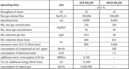
As opposed to that, an SCR plant produces additional CO2 emissions of 15,000 t/h just because it consumes a lot of additional energy for the generation of electricity which is needed for the higher blower capacity and for the gas-fired duct burners (Figure 18).
Table 2: Operating data – SCR versus SNCR (per line)
ammonia water power input natural gas steam
240 °C 240 °C
catalyst
235 °C 235 °C 210 °C
210 °C 95 °C
95 °C
120 °C 120 °C heat exchanger
Figure 18:
SCR and flue gas reheating
operating data unit SCR NH4OH SNCR NH4OH
24.5 %
throughput of waste t/h 25 25
flue gas volume flow Nm³/h, tr. 100,000 100,000
operating hours h/a 8,000 8,000
NOx raw gas concentration
mg/Nm³ 330 330
NOx clean gas concentration 45 50
NOx reduction per line kg/h 28.5 28
NOx reduction (three lines)
t/a 684 672
ammonia water 24.5 % (three lines) 800 4,000
consumption of compressed air incl. agam Nm³/h – 500
consumption of deionized water m³/h – 1.2
additional electr. consumption of ID fan MWh/a 6,100 –
CO2 for additional energy (three lines) t/a 12,000 –
consumption of natural gas Nm³/a 6,600,000 –
Table 2 indicates that operating costs for reducing one ton of NOx are by far higher when using SCR technology than they would be in an SNCR plant. From other studies it can be concluded that the investment costs for SCR are at least five times higher than for SNCR which clearly shows that an SNCR plant with its better cost/benefit ratio is more economical and therefore much more effective protecting the environment.
6. Summary and outlook
The results of several years of operation with a number of SNCR plants show that the current and future BREF standards can not only be met, but even exceeded in many cases. Many plants which have been operated for many years were retrofitted recently and comply now with the new standards.
Flue Gas T
The modification of an existing SNCR system is relatively easy: Generally, some extra lances, advanced temperature measurement systems and a modernized control system are sufficient.
It is known that the investment costs for SCR exceed those for SNCR, but – depending on the design of the individual projects – these costs can be five to ten times higher for SCR than for SNCR. Another well-known fact is that because of the chemical condi- tions in the SNCR process, the consumption of reagent is approximately three times higher than with SCR. However, it is usually not considered that this effect is by far compensated due to the savings of other consumables.
Furthermore, the SNCR process has been continuously developed and improved over the last years. It has reached a high technological standard and has widely found accept- ance in the meantime, especially with regard to NOx reduction in the flue gas of small to medium sized combustion plants burning for example waste, refuse derived fuel, and biomass. Depending on the design of the plant it is possible to maintain emission limits of < 100 mg/Nm³ NOx in clean gas and NH3 slip < 10 mg/Nm³, particularly when taking into account the cost/benefit ratio, the SNCR technology is well-established and accepted as Best Available Technology (BAT) for NOx reduction.
7. Literature
[1] IKW Rüdersdorf GmbH: IKW Rüdersdorf – Emissionswerte. Retrieved: November 12, 2017;
from: http://ikw-rüdersdorf.de/emissionswerte.htm
[2] Moorman, F.; Stubenhöfer, C.; von der Heide, B.: Umrüstung der Abfallverbrennungsanlage Wijster/Niederlande von SCR auf SNCR. In: Thomé-Kozmiensky, K. J.; Beckmann, M. (Eds.):
Energie aus Abfall, Band 10. Neuruppin: TK Verlag Karl Thomé-Kozmiensky, 2013, pp. 683-702 [3] SRS EcoTherm GmbH: Emissionswerte der MVA Salzbergen 2016. Retrieved: November 12,
2017; from: http://www.bisalzbergen.de/2016ZusammenfassungMVAwerte.pdf
[4] von der Heide, B.: Ist das SNCR-Verfahren noch Stand der Technik? In: Thomé-Kozmiensky, K. J.; Beckmann, M. (Eds.): Energie aus Abfall, Band 4. Neuruppin: TK Verlag Karl Thomé- Kozmiensky, 2008, pp. 275-293
Contact Person
Dipl.-Ing. Bernd von der Heide
Mehldau & Steinfath Umwelttechnik GmbH Chief Executive Officer (CEO)
Management Alfredstraße 279 45133 Essen GERMANY +49 20143783-0 zentrale@ms-umwelt.de
Bibliografische Information der Deutschen Nationalbibliothek Die Deutsche Nationalbibliothek verzeichnet diese Publikation in der Deutschen Nationalbibliografie; detaillierte bibliografische Daten sind im Internet über http://dnb.dnb.de abrufbar
Thiel, S.; Thomé-Kozmiensky, E.; Winter, F.; Juchelková, D. (Eds.):
Waste Management, Volume 9 – Waste-to-Energy –
ISBN 978-3-944310-48-0 Thomé-Kozmiensky Verlag GmbH
Copyright: Elisabeth Thomé-Kozmiensky, M.Sc., Dr.-Ing. Stephanie Thiel All rights reserved
Publisher: Thomé-Kozmiensky Verlag GmbH • Neuruppin 2019 Editorial office: Dr.-Ing. Stephanie Thiel, Elisabeth Thomé-Kozmiensky, M.Sc.
Layout: Claudia Naumann-Deppe, Janin Burbott-Seidel, Sarah Pietsch, Ginette Teske, Roland Richter, Cordula Müller, Gabi Spiegel Printing: Universal Medien GmbH, Munich
This work is protected by copyright. The rights founded by this, particularly those of translation, reprinting, lecturing, extraction of illustrations and tables, broadcasting, micro- filming or reproduction by other means and storing in a retrieval system, remain reserved, even for exploitation only of excerpts. Reproduction of this work or of part of this work, also in individual cases, is only permissible within the limits of the legal provisions of the copyright law of the Federal Republic of Germany from 9 September 1965 in the currently valid revision. There is a fundamental duty to pay for this. Infringements are subject to the penal provisions of the copyright law.
The repeating of commonly used names, trade names, goods descriptions etc. in this work does not permit, even without specific mention, the assumption that such names are to be considered free under the terms of the law concerning goods descriptions and trade mark protection and can thus be used by anyone.
Should reference be made in this work, directly or indirectly, to laws, regulations or guide- lines, e.g. DIN, VDI, VDE, VGB, or these are quoted from, then the publisher cannot ac- cept any guarantee for correctness, completeness or currency. It is recommended to refer to the complete regulations or guidelines in their currently valid versions if required for ones own work.