Layout Planning of Waste-to-Energy Plants
Falko Weber
The layout planning of waste incineration and solid recovered fuel power plants is sub- ject to certain local and project-specific boundary conditions alongside the technical ones. The results of this planning have significant influence on the functionality and operation of the plant, as well as on other criteria.
Layout planning or concrete general layout planning can be seen as comprehensive planning for a complete waste incineration plant and must exploit degrees of freedom in planning, while allowing the proper key aspects to be worked out with allowance for existing prerequisites, boundary conditions and client-side wishes and specifications.
What do we mean by optimal layout planning? An optimum has been reached when a maximum amount of functionality and efficiency for operation of the plant has been achieved according to the possibilities and specifications of the project and of the cus- tomer. Between boundary conditions and objectives an atmosphere of tension arises that has to be mastered in the planning process of the project. Alongside the technical aspects it is project discipline that plays a key role here, i.e., how early on can final fundamental decisions be made in the general planning so that implementation of the objectives is possible in supply and delivery as well as in construction, and according to deadlines in further project realization.
In the details of a technical system, e.g., the location of a valve, one can generally find remedies with manageable efforts.
The influence of the more or less good general layout of a waste incineration plant is far reaching in contrast. The subsequent modifications of the complete waste delivery logistics system, the O&M areas, and access as well as disassembly concepts or the distances from buildings and escape routes can only be achieved with sometimes considerable effort.
It is important at the start of a new construction project to place the necessary impor- tance on the project organization of the general layout planning. The general layout represents the brackets of the room and structure planning for structural engineering, installation engineering and the EI&C technology.
A number of aspects of general layout planning shall be touched upon in the following remarks and explanations. Along with the content-related and technical contexts, the step-by-step approach of a new construction project will be explained.
Further explanations are based on a waste incineration plant using grate firing.
Important superordinate aspects:
• Specifications and consideration of special requirements should be regarded early on in the project.
• Selection of the best technical solutions and the functional layout are decisive cri- teria for operation of the plant.
• The plant has to be brought into line with site and environmental requirements.
Individual aspects to be regarded in detail are:
• available construction and assembly area,
• requirements from the approval notification for the plant – e.g., maximum const- ruction height,
• waste fuel logistics – by road, rail, private delivery, etc.,
• fire safety requirements, escape routes/stair towers,
• local special building requirements – groundwater, foundations, terrain profile, etc.,
• architectural requirements,
• requirements for the assembly procedure,
• consideration or integration of older systems at the site,
• number of firing lines,
• local weather conditions – with regard to open or closed design of plant compo- nents, type of facades, materials, heating.
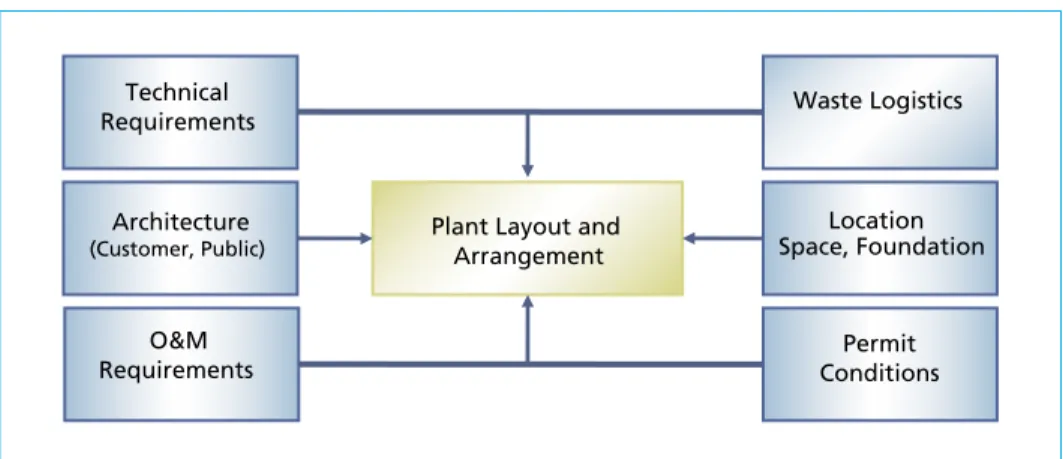
Figure 1 shows influences and requirements of general layout planning.
Figure 1: Influences and requirements
What documents and information are important in the initial considerations of the general arrangement plan?
• Overall layout plan with construction limits and property boundaries,
• ground elevation data,
• main connecting roads, access roads to the plant,
Plant Layout and Arrangement Technical
Requirements Waste Logistics
Location Space, Foundation Architecture
(Customer, Public)
O&M
Requirements Permit
Conditions
• data on the planned delivery of waste – rail, road, container, etc.,
• water and waste water connections, cooling water on hand,
• grid connection – location, technical data,
• noise requirements – expert‘s report –, location of residential areas,
• district heating or process steam connections,
• architectural concept or local guidelines from existing buildings.
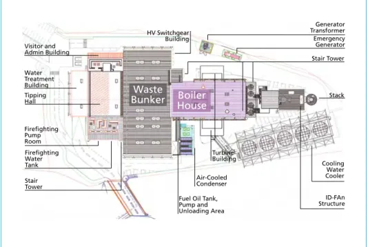
Example of a general arrangement plan
Figure 2: Example of an overall layout plan for a waste-to-energy plant, with a firing unit and with delivery of the waste by truck
General arrangement – necessary buildings and plant components Depending upon:
• the planned plant technology,
• the number of firing lines and the flue gas cleaning line and its hook-up,
• delivery logistics of the waste,
• the slag and filter dust storage and treatment concept on-site or externally,
• the cooling concept – water or air cooling – of the turbine exhaust steam,
Water Treatment Building Tipping Hall
Firefighting PumpRoom
Stair Tower
Cooling Water Cooler Air-Cooled
Condenser Turbine Building
Stair Tower HV Switchgear
Building
Generator Transformer Emergency Generator Visitor and
Admin Building
Stack
ID-FAn Structure Fuel Oil Tank,
Pump and Unloading Area Firefighting
Water Tank
Waste
Bunker Boiler House
• the necessary interim storage of additional fuels, treated water on the basis of local interfaces and supply situations,
• specific customer requirements,
• sound technology requirements,
• architectural guidelines,
• the electrical engineering concept.
Concrete plant areas and buildings can be determined, specific to each project. In the following the most important plant areas and buildings are listed, which are required, as a rule, for a new construction project of a waste incineration plant:
HV Switchgear Building Boiler House
Main Switchgear Building Stair Tower
Service Transformer Stack
Generator Transformer Flue Gas Heat Exchanger
Emergency Generator Turbine Building
Tipping Hall Air-Cooled Condenser
Waste Bunker Cooling Water Cooler
Baler and Bale Storage Workshop and Stores
Fuel Oil Tank, Pump and Unloading Area ID-Fan Structure
Bottom Ash Storage Visitor and Admin Building
Firefighting Pump Room Gate House
Water Treatment Building Vehicle Traffic Areas
Firefighting Water Tank Weigh Bridges
Demin Water Tank Visitor/Staff Parking Areas
Tanks for Water Treatment Chemicals Perimeter Fences and Gates
Urea Water Tank Landscaping and Rainwater
Retention Other Chemicals Storage
Dimensioning the main components and storage volumes
Along with determining technical details, which are crucial in a waste incineration plant, the volumes for interim storage of fuels, residual materials, wastes and operating
materials must be determined. This dimensioning of storage has, in turn, influence upon certain plant components and their layout:
Points to be especially observed – key point waste bunker:
• waste bunker capacity,
• ground water level – location of the waste bunker bed, tipping height,
• waste quality – grain size, stackability, density on delivery and during storage,
• waste delivery logistics, waste transfer point in waste bunker,
• number and design of waste cranes, operational mode,
• frequency and times of waste delivery,
• slag storage capacity – raw slag – or storage volume for treated slag,
• number of firing lines.
Structure of a waste bunker
The building structure of the waste bunker is derived from the planning-side boundary conditions and the already-described aspects:
• delivery points for the waste,
• adjacent buildings, such as switchgear building, stair tower,
• slag loading point,
• slag hopper level for waste feeding,
• crane level for the waste crane(s),
• planned bunker extension, if necessary,
• planned bulky waste cutters, if necessary,
• planned waste baling press system, if necessary,
• wear-resistant or wear-protected bunker interior walls and surfaces.
The structure of the waste bunker is derived from already-mentioned criteria and requirements as well as from static dimensioning.
The static dimensioning of the waste bunker is important insofar as there are limitations caused through the intermediate supports in the bunker walls (pilaster strips) in waste delivery as well as crane operation of the waste. Special wear and impact protection is required here. The interior walls of the bunker are also to be protected against impact from the waste cranes and against wear.
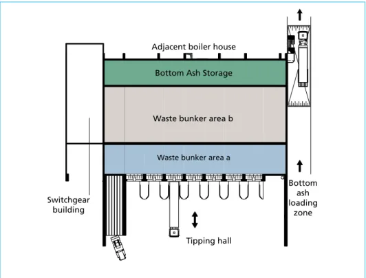
Figure 3: Ground plan of waste bunker
Figure 4: Waste bunker, longitudinal section (example)
+36,05
-7,00
Tipping
hall Waste
bunker area a Waste
bunker area b Bottom ash loading zone Adjacent boiler house
Bottom Ash Storage
Waste bunker area b
Waste bunker area a
Tipping hall Switchgear
building
Bottom ash loading
zone
Layout of the boiler house and the flue gas cleaning unit The boiler house with the firing system and the boiler unit is connected directly to the waste bunker. The flue gas cleaning unit is arranged after the boiler house.
The following aspects are to be considered superordinately in the layout planning (boiler and flue gas cleaning unit):
• number of firing lines,
• number and hook-up – flue gas flow – of the flue gas cleaning units,
• type of flue gas cleaning – cleaning method, cleaning stages,
• enclosure of the boiler house,
• enclosure of the flue gas cleaning unit or open construction,
• shared building – steel construction, enclosure – for boiler and flue gas cleaning unit planned?
• determine locations of main columns,
• location and height of waste feed hopper,
• escape routes, stair towers in boiler and flue gas cleaning unit, transition to other buildings,
• maximum allowable boiler roof height,
• construction design of the boiler – horizontal or vertical design,
• boiler house access for trucks,
• disassembly concept for the boiler heating surfaces,
• heating, smoke and heat extraction,
• adjacent buildings, fire protection.
Additional points especially for the flue gas cleaning unit:
• building for the storage of dosing materials and chemicals planned,
• layout of the compressed air generating system,
• location and minimum height of the smokestack, location of the emissions measuring points.
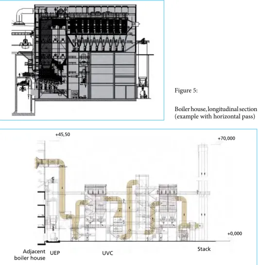
Figure 6: Flue gas cleaning unit with ash silo and stack, longitudinal section (example) Stack UEP UVC
+45,50
+70,000
+0,000
Adjacent boiler house
Figure 5:
Boiler house, longitudinal section (example with horizontal pass)
with 12t
Cran 2
Under Load 33,9 kN/m2 (SLW 60)
Boiler Hall
Figure 7: Example of crane setup for overhaul of boiler heating surfaces, longitudinal section
Turbine house and steam turbine generator set What is important to observe in the layout planning of the water-steam cycle and especially the components in the turbine house:
• turbine concept,
• selection of the condensing system/cooling of exhaust steam,
• layout of the steam turbine generator set,
• layout of auxiliary components.
It has to first be determined how and what kind of energy conversion is provided for and thereby which turbine concept:
• pure power generation, i.e. pure steam condensation,
• back-pressure turbine for district heating or process steam supply,
• steam condensation with partial steam extraction for proportional district heating or process steam supply.
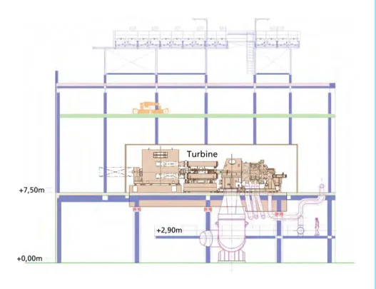
+0,00m +7,50m
+2,90m Turbine
Figure 8: Section of a turbine building with turbine deck (example)
For the selection of the condensing system the following are to be considered:
• air condenser,
• water condenser – cooling water via cooling circuit and wet cooling tower,
• water condenser – open cooling circuit, cooling water from river or sea.
Layout possibilities of the steam turbine generator set:
• ground-level placement – i.e. without turbine deck,
• placement with turbine deck,
• placement of exhaust steam upward, downward, horizontal.
A short live steam line from the boiler to the turbine generator set is to be strived for so that little energy is lost as a result of pressure loss.
In addition, topics such as operating and maintenance inspection surfaces are to be planned, pipe ways determined, a turbine house access road planned and, if necessary, a crane installation provided.
Infrastructure – fuel logistics, roads, access roads, surface areas
The infrastructure of a waste incineration plant is of enormous importance as much with regard to external accessibility and interfaces as it is within the plant itself. The daily traffic takes place here, and operating/observation/monitoring and maintenance measures are carried out.
Added to this, the infrastructure of the waste incineration plant is to be taken into consideration in a meaningful way for its construction. Synergetic effects come about when the construction site access roads and the circumference of the construction site can be used as fire department bypass roads from the very beginning, and these roads can also be used in the final state.
The main criteria for the infrastructure of a waste incineration plant:
• access from public roads, gatekeeper, scale,
• fire department bypass around the plant,
• waste bunker delivery area,
• access roads, parking spaces for tank installations and silos,
• general parking spaces,
• interim storage of waste for control purposes,
• waste delivery logistics,
• interim storage of waste outside the waste bunker planned (?), waste baling press planned (?),
• administrative building, storage building, workshop,
• visitors‘ presentation and reception rooms,
• location of the permanent work stations,
• escape routes, location of stair towers,
• surfaces for maintenance – depositing surfaces, assembly/disassembly routes, crane locations,
• fire protection equipment, hydrants,
• room for possible plant expansion.
Figure 9: 3D model of a planned waste-to-energy plant
Summary Waste incineration plants require special attention in the layout planning of the overall plant. The sites available or planned for such plants often have demanding boundary conditions for construction of the plant and for the final state of the structure.
Unilateral compromises that benefit other key points only become apparent in later operation, but these are then day-to-day and long-lasting. Later modifications and optimizations are only possible within limits, with increased effort and at the burden of other problems and costs.
The task of general layout planning lies in being able to determine the main requirements for the site at an early stage and to specifically implement these. The consideration of other criteria, such as architecture or one-time increased investment costs that favor the efficiency of the plant, can lead to a special situation.