As your expert for refractories we create innovative solutions for all industries. For more than 80 years.
Worldwide. The closeness to our customers has made us strong. We focus on the specific requirements of our business partners and provide customized complete solutions. We do not know any limits in Refracotries. In this sense we are always willing to be at your service.
in Waste-to-Energy
Thermische Anlagen Bazenheid, Switzerland Refractory Lining Boiler 1
Waste Incineration
Upscaling Combustion Grates – Technical Challenges
Tom Croymans, Nicolas Maertens, Peter Van de Moortel, Kenneth Villani and Rudi Pittoors
1. Challenges of large MSW incineration grates ...208 2. Solutions ...210 2.1. Flexible matrix grate technology ...210 2.1.1. Flexibility by modularization by means of lanes, elements,
zones and cells ...211 2.1.2. Built-in grate movement flexibility via sliding and tumbling tiles ...212 2.2. Sigma matrix combustion control ...213 2.3. The combination of flexible matrix grate technology
and the Sigma matrix combustion control system ...215 3. Conclusion ...216 4. References ...216
Worldwide 2.01 billion tons of municipal solid waste (MSW) was generated in 2016 [2].
Without proper actions the World Bank expects this number to rise to 3.4 billion tons by 2050 [2]. Rising population and urbanization lead to financial, environmental and logistic challenges of waste management, especially in densely populated areas [1, 3, 4].
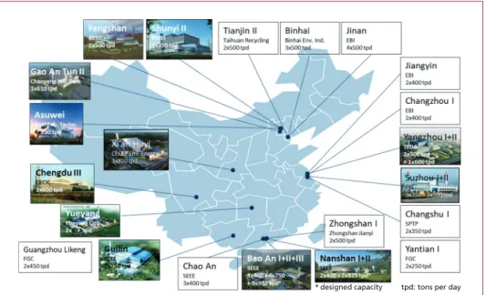
Addressing these challenges requires directing such waste towards large centralized waste treatment plants. Consequently, capacities of Energy from Waste (EfW) installa- tions to treat MSW are increasing year on year and so are line sizes. This trend is clearly shown in Figure 1 where in general higher treatment capacity per line can be seen in more recent plants. A milestone in terms of treatment capacity is the Bao’an – located in the Shenzhen area of P.R. China known for its leading position when it comes to high tech – EfW plant which treats 8,800 tons of MSW/day [5]. Technology suppliers are not only experiencing increasing demand for larger line capacities in China, this is also a trend seen in Europe and the Middle East.
To meet these trends and market demands technology suppliers not only need to develop larger grates but also develop the adequate combustion control algorithms to properly manage the combustion process. Consequently, only a combination of thought through hardware and intelligent software allows optimizing the entire combustion process in terms of process parameters such as throughput, process stability, use of consumables, meeting emission levels, ash quality etc.
Waste Incineration
Figure 1: Keppel Seghers’ reference plants in P.R. China developed over the last two decades, with an indication of treatment capacity per site; in general, the higher the treatment capacity per line, the more recent the plant
1. Challenges of large MSW incineration grates
Upscaling is a complex and challenging task typically driven by the industrial requi- rement for better economies of scale. Typically, the cost of one incineration line of a certain capacity is 10 – 15 % less expensive than two lines with the same total capacity.
In terms of challenges related to upscaling, the EfW industry is no exception. Challen- ges in the EfW sector are typically related to parameters such as heterogeneity in the municipal solid waste characteristics such as the Lower Heating Value (LHV), density, water content, and inert content for example. On smaller grates, the throughput is less and therefore such heterogeneity is naturally limited, however for large grates this heterogeneity leads to challenges in maintaining proper combustion over the entire large grate surface due to disturbances caused by local variations of the waste quality on the grate. Conventional non-flexible grate technology cannot cope with these local disturbances since those grates have no means to manage the heterogeneity properly.
An example of such a disturbance is:
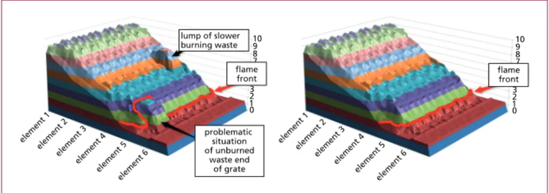
• snake head formation: Large lumps of relatively low LHV waste, compared to the adjacent waste are harder to burn and consequently affect the flame front in two ways: 1) separation of the flame front and 2) hold up of the flame front.
1) The primary flame front – typically situated at the transition between main and post combustion zone (as shown in Figure 2) – gets separated. This is due to the fact that the pile of low LHV waste is harder to burn. This pile moves forward on the grate and, if no specific control actions are taken, ultimately breaks through
* designed capacity tpd: tons per day
Waste Incineration
and separates itself from the primary flame front towards a lower combustion zone (e.g. post combustion zone) – as shown in Figure 2. Consequently, the waste upstream this pile cannot ignite in the right combustion zone. Clearly this situation is undesirable and requires local correction measures to prevent slowing down the entire combustion process.
2) In order to correct this situation through conventional grate technology, the incineration over the entire grate needs to be slowed down to avoid unburned material getting into the ash bunker. The larger the grates, the higher the risk of having a substantial pile of waste burning too slowly on the grate. This side effect will force the process to slow down the waste transport and throughput and forces the control system to run at the speed of the slowest burning waste (running at the speed of the waste with the lowest LHV on the grate). In sum- mary; the larger the grate the more likely it is that the waste heterogeneity will have a negative impact on the capacity of the grate and overall plant.
In the case of conventional non-flexible combustion grate technology heterogeneity phenomena has an impact on the flame front and consequently negatively affects:
• Throughput: slower burning areas slow down the combustion on the entire grate.
This means that local disturbances on the grate affect the combustion as a whole.
• Steam production: unstable steam production due to an inhomogeneous flame front and frequent reduced steam flow/loss in power to deal with those disturbances.
• Ash quality: elevated levels of unburned carbon in the ashes (LOI), if not properly dealt with by the combustion control system.
• Homogeneity of the flue gases: as there are spots of smoldering material which lead to lower performance of the flue gas cleaning systems (e.g. SNCR) and potentially higher emissions (e.g. CO; TOC).
• Hot/cold spots in boiler.
element
1 1023
109 87
1023 109 87
element 2 element
3 element
4 element
5 element
6
element 1 element
2 element
3 element
4 element
5 element
6 lump of slower
burning waste flame front
problematic situation of unburned
waste end of grate
flame front
Figure 2: Schematic example showing the waste layer thickness on the grate and local disturbances on the grate affecting the combustion as a whole; right figure represents the normal desi- red situation; left figure represents a situation with slower than average, burning waste lumps; formation of a snake head which is a pile of non-burning waste finally breaking through the primary flame front
It is clear that heterogeneity challenges have a negative impact revenue generation, operation cost and maintenance cost.
Waste Incineration
2. Solutions
It is common sense that good bunker design and bunker management are essential to have a stable and efficient combustion process. Nevertheless, even with optimal bunker management conditions there will still be a substantial residual LHV variation in the waste fed to the furnace, which is amongst other factors related to the size of the waste cranes which increases together with the EfW line size. This intrinsic condition of the waste fed to the furnace means that the grate design and design of the combustion control system will have to be able to deal with it.
Large grates not only have to deal with LHV variations in time (LHV variation over the length of the grate) but also LHV variations across the width of the grate.
Both the above mentioned phenomena, as well as, the subsequent consequences can be addressed by:
• the use of (multiple) smaller grates or
• a combination of a large flexible grate and adequate software to properly steer this grate and ensure that the large grate achieves the same relative performance as a small grate.
The solution to enjoy both economies of scale and superior process performance is the Keppel Seghers’ (KS) unique flexible matrix grate technology combined with Sigma matrix control algorithms. This unique combination of reliable and flexible hardware and worldclass combustion software enables optimal combustion control parameters in every square meter / zone of the grate.
2.1. Flexible matrix grate technology
There are two levels of flexibility in combustion grate technology i.e. 1) flexibility by modularisation and 2) built-in grate flexibility by independent degrees of movement per grate cell.
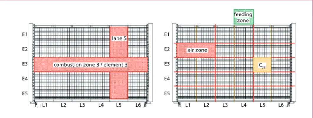
1) The first level of flexibility is linked to the mechanical design of the grate. The grate is divided in a matrix by means of lanes and elements which consequently divides the grate into different zones and cells as shown in Figure 3.
2) The second level of matrix flexibility is built-in by means of a combination of sliding (transport of the waste) and tumbling (provoking ignition of waste ha- ving difficulties to ignite, without transporting it) tiles, shown in Figure 4. In this matrix distribution each cell or collection of cells has its own hardware and instrumentation. Each cell can be controlled independently of the neighboring cells.
Waste Incineration Figure 3: Illustration of flexible matrix grate technology; left picture shows how the incineration
grate is divided into lanes and elements; right picture shows the formation of a matrix grate marking the matrix flexibility by different air or feeding zones and cells
L1 L2 L3 L4 L5 L6
E1 E2 E3 E4 E5
E1 E2 E3 E4 E5
air zone
feeding zone
C35
L1 L2 L3 L4 L5 L6
combustion zone 3 / element 3 lane 5
Figure 4: Sectional view of the air-cooled grate set-up with indication of sliding tile (left) and tumbling tile (right) movement actions
2.1.1. Flexibility by modularization by means of lanes, elements, zones and cells The flexible matrix grate technology consists of a combination of modular pre-assembled lanes and elements (shown in Figure 3 and Figure 5). By means of these pre-assembled modules, high flexibility in terms of grate size and waste throughput can be achieved through (combined) variation of:
• the number of lanes and
• the number of elements.
This allows the matrix grate to be tailored according to the needs of each specific case.
With this lane and element design, different zones and cells are established (shown in Figure 3) of which individual process parameters are monitored and control outputs
Waste Incineration
given. Based on this monitoring, the individual zones and cells are controlled and adjusted to achieve the optimal combustion results for the local waste characteristics.
This is done in order to attain the requested throughput and energy production whilst simultaneously assuring the required burn-out quality of the combustion ash. This de- sign also allows targeted actions linked to the afore mentioned heterogeneity challenges faced by larger grates and thereafter local combustion disturbances.
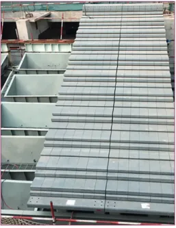
Figure 5: Picture of matrix grate installation on site
2.1.2. Built-in grate movement flexibility via sliding and tumbling tiles
Figure 4 shows the sliding, tumbling and fixed tiles and their configuration which all have a role in the efficient burning of waste. The function of the sliding tiles is to en- sure that the targeted waste throughput is achieved by transporting the burning waste bed over the combustion grate. The tumbling tiles are a unique KS feature, designed to ensure a complete combustion of low to medium calorific waste. By means of a so- called poking action the breakdown and improved mixing of clogged waste lumps is ensured. In addition, this action facilitates the introduction of primary combustion air, fed from below the grate, for waste drying and combustion. This principle, i.e.
independent waste mixing and transport movement, established by different types of tiles, allows the system to adapt swiftly to fluctuations in waste composition over both short and long term periods while addressing the challenges of larger grates. More details on this tile system can be found in [6].
Via the design of lanes and elements, the movement of the sliding and tumbling tiles can be varied both down the length and across the width of the grate.
To master the control on this detail of local combustion on the grate an autonomous combustion control system is required.
A non-exhaustive list of advantages rela- ted to the reliable hardware of this flexible matrix grate technology includes:
• flexible primary combustion air con- trol per air zone,
• flexible waste feeding per lane,
• flexible waste transport speed per lane/cell and
• flexible poking per cell to solve local disturbances.
Waste Incineration
2.2. Sigma matrix combustion control
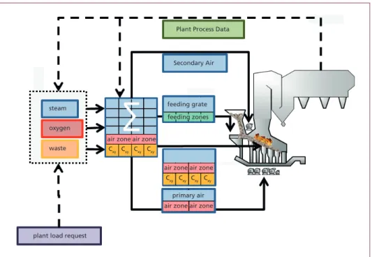
The flexible matrix grate technology hardware needs to be supported with an adequately advanced software. The Sigma matrix combustion control system is a level 3 autonomous control system (see next paragraph) and ensures a stable operation of the plant thanks to advanced integration of precise instrument measurements and selected feedback signals of process parameters, such as, but not limited to steam flow and oxygen level.
These are translated into an adjustment of combustion air supply and targeted grate movements (sliding and tumbling actions) at a cell by cell level. It must be noted that the input data and actions are at cell and/or zone level resulting in a flexible and local approach including their own feedback signals. Through this set-up a collection of various combustion influencing parameters are monitored at all times. Due to this wide variety of combustion control parameters only a smart control system allows guaranteeing an optimized, stable and reliable combustion process output.
The level 3 autonomous combustion control system is a level of combustion automation for which the operator is still required to input some initial setpoints but the control system will autonomously adapt to changing combustion conditions. The system is able to autonomously adapt the steam setpoint if required and autonomously decide about the best actions to solve process disturbances to keep the process within its boundary conditions (emissions, ash quality, throughput, stable steam production, etc).
Because of boiler legal constraints, the boiler critical safety actions are programmed in a separate safety PLC.
Plant Process Data
Secondary Air
air zone Cxy Cxy Cxy Cxy Cxy
Cxy Cxy Cxy air zone
air zone air zone
steam
oxygen
waste
air zone
air zone primary air feeding grate feeding zones
plant load request
Figure 6: Schematic illustration of Sigma matrix combustion control system
Waste Incineration
Figure 6 illustrates this concept starting from the plant load request set point (steam production or waste throughput) demanded by the control room operator via the combustion control system. This action directly responds to the input by adapting the dosing movements of the feeding grates, by varying the intensity of sliding and tumbling on the combustion grate and by adjusting the primary and secondary combustion air flows. The difference between measured values and the combustion control calculated set points defines the magnitude of the action of the individual controllers. The controller outputs finally keep the plant in a stable mode of operation.
On top of those basic control actions, the Sigma matrix combustion control system will detect waste and incineration disturbances in the furnace and will autonomously compensate locally on the grate to keep the desired fire front and burn out quality at all times.
0-30 -01 -02 -03 -04 -05 -06 -07
superheated HP steam_flow main steam present value (ton/h) thermal load 1 h avg. (MWth) thermal load 8 h avg. (MWth) LHV 1 h avg. (MJ/kg) LHV 8 h avg. (MJ/kg)
-08 -09 -10 -11 -12 -13 -14 -15 -16 -17 -18 -19 10
20 30 40 50 60 70 80 100
0 2 4 6 8 10 12 14 16 18 thermal load MWth
steam flow ton/h
LHV MJ/kg steam flow ton/h
time
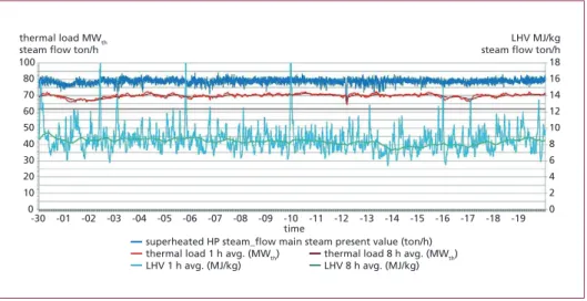
Figure 7: Actual performance of an air cooled grate over a period of 20 days (logging interval = 1 minute)
Figure 7 shows the results of a large scale grate with matrix control features at feeding grate and air distribution. While assuring the burn out quality of the bottom ashes these first local acting and compensating matrix control features are able to keep the steam stability within a standard deviation of 2 % on a minute time basis without operator intervention. The additional features concerning local different grate movements are still under test, but definitely will further improve the overall performance and cont- rollability of the fire.
Hence, in the case of an air cooled grate the software allows controlling up to:
• 104 individual grate movements (sliding 64 and tumbling 40) matrix elements,
• 8 individual feeding grate movements and
• 32 individual air dosing matrix zones.
Waste Incineration
2.3. The combination of flexible matrix grate technology and the Sigma matrix combustion control system
The combination of flexible grate technology and Sigma matrix combustion control leads to unparalleled advantages which are unable to be met with conventional incinera- tion technology. In terms of large incinerator grates, the proposed highly technological combination leads, because of the advanced control grid, to
• sustainable and higher overall throughput,
• stable temperature and oxygen levels,
* much longer lifetime boiler (less corrosion)
* less slagging leads to higher boiler efficiency which leads to more revenue
* lower CO emissions
* lower ammonia consumption for NOx removal
• high steam stability under varying LHV conditions and
* higher average steam output generates more revenue (energy and throughput)
* turbine runs at higher efficiency generates more revenue
* optimal design steam condensate circuit leads to less costs
* less wear and tear leads to less costs
• ensuring Loss of Ignition targets are met at all times
* better ash quality
* avoid unburned material, negatively affecting bottom ash reuse.
Of course also for the flexible matrix grate technology, the highest standards of steam stability are met. As with other KS grate technologies steam stability of less than 2 % standard deviation, on minute values, are achieved during periods of weeks for large grates. This exceptionally low amplitude (standard deviation) of steam flow fluctuations allows the installation to run constantly much closer to its ultimate design maximum without risk of damage to the installation. This in turn has a direct impact on the Return On Investment realized by the owner.
In summary, through its unique design the flexible matrix grate is divided in lanes, elements, zones and cells. This matrix set-up, in combination with a set of tumbling and sliding tiles, allows extremely flexible operation of the grate. The Sigma matrix combustion control smartly monitors and controls the grate based on data received from the advanced integration of precise instrument measurements and selected process parameters feedback signals.
Waste Incineration
3. Conclusion
From an economic point of view, large combustion grates can deliver a financial benefit in comparison to multiple smaller grates. However, increasing grate sizes lead to tech- nical challenges of which controlling the heterogeneity of waste across the combustion grate width is the most important. Controlling this heterogeneity cannot be addressed with conventional combustion technology.
A combination of flexible matrix grate technology with advanced intelligent software can overcome the challenges faced by such large grates. Keppel Seghers’ proprietary technology ensures maximized throughput, maximized stable energy production whilst simultaneously reducing long-term wear and ensuring full compliance of solid and gaseous parameters with emission limits at all times.
4. References
[1] Hoornweg, D.; Freir, M.: Building Sustainibility in an Urbanizing World - World Bank Group, 2013 [2] Kaza, S.; Yao, L.; Bhada-Tata, P.; Van Woerden, F.: What A Waste 2.0 A Global Snapshot of Solid
Waste Management to 2050 - World Bank Group, 2018
[3] United Nations: World Urbanization Prospects: The 2018 Revision, 2018
[4] United Nations: World Population Prospects the 2017 Revision Key Findings & Advance Tables, 2017 [5] Villani, K. et al.: Delivering high-throughput waste-to-energy solutions in the P.R.China – the
Shenzhen Bao‘an case., Sel. China Sanit. Technol. Dev. Facil., 2013
[6] Villani, K. et al.: Development of Flexible Combustion Grate and Combustion Control Techno- logy, Proc. Venice 2016, Sixth Int. Symp. Energy from Biomass Waste, 2016
Contact Persons
Dr. Tom Croymans Keppel Seghers Innovation Manager Hoofd 1
2830 Willebroek BELGIUM +32 3 8807788
tom_croymans@keppelseghers.com
Ing. Peter van de Moortel Keppel Seghers
Hoofd 1
2830 Willebroek BELGIUM +32 3 8807700
peter_vandemoortel@keppelseghers.com
Bibliografische Information der Deutschen Nationalbibliothek Die Deutsche Nationalbibliothek verzeichnet diese Publikation in der Deutschen Nationalbibliografie; detaillierte bibliografische Daten sind im Internet über http://dnb.dnb.de abrufbar
Thiel, S.; Thomé-Kozmiensky, E.; Winter, F.; Juchelková, D. (Eds.):
Waste Management, Volume 9 – Waste-to-Energy –
ISBN 978-3-944310-48-0 Thomé-Kozmiensky Verlag GmbH
Copyright: Elisabeth Thomé-Kozmiensky, M.Sc., Dr.-Ing. Stephanie Thiel All rights reserved
Publisher: Thomé-Kozmiensky Verlag GmbH • Neuruppin 2019 Editorial office: Dr.-Ing. Stephanie Thiel, Elisabeth Thomé-Kozmiensky, M.Sc.
Layout: Claudia Naumann-Deppe, Janin Burbott-Seidel, Sarah Pietsch, Ginette Teske, Roland Richter, Cordula Müller, Gabi Spiegel Printing: Universal Medien GmbH, Munich
This work is protected by copyright. The rights founded by this, particularly those of translation, reprinting, lecturing, extraction of illustrations and tables, broadcasting, micro- filming or reproduction by other means and storing in a retrieval system, remain reserved, even for exploitation only of excerpts. Reproduction of this work or of part of this work, also in individual cases, is only permissible within the limits of the legal provisions of the copyright law of the Federal Republic of Germany from 9 September 1965 in the currently valid revision. There is a fundamental duty to pay for this. Infringements are subject to the penal provisions of the copyright law.
The repeating of commonly used names, trade names, goods descriptions etc. in this work does not permit, even without specific mention, the assumption that such names are to be considered free under the terms of the law concerning goods descriptions and trade mark protection and can thus be used by anyone.
Should reference be made in this work, directly or indirectly, to laws, regulations or guide- lines, e.g. DIN, VDI, VDE, VGB, or these are quoted from, then the publisher cannot ac- cept any guarantee for correctness, completeness or currency. It is recommended to refer to the complete regulations or guidelines in their currently valid versions if required for ones own work.