Dorfstraße 51 D-16816 Nietwerder-Neuruppin Phone: +49.3391-45.45-0 • Fax +49.3391-45.45-10 E-Mail: order@vivis.de TK Verlag GmbH
order now www. .de
Waste-to-Energy Plants
– Germany –
The actual book 2016|2017 carries forward the survey of waste-to-energy plants in the Federal Republic of Germany which started in the 1990´s. With the first publication we have two books which complement each other perfectly. Both books provide extensive information about the installed technology and the environmental impact of the waste-to-energy plants.
The quality of the new inquiry has been extended in terms of the technical data. Existing gaps regarding the data were partially filled.
This is the result from the considerable assistance of numerous plant operators. The publication on hand shall be seen as an interims report. The work on the data acquisition will be continued. For this reason we ask plant operators and manufactures to critically review the release data.
• 33 minucipal solid waste incineration plant
• 7 solid recovered fuel power plant
• 1 Sonderabfallverbrennungsanlage
The further investigations will be extended to the missing German waste-to-energy plants as well as to plants in other countries.
Elisabeth Thomé-Kozmiensky
1.5. Generalunternehmer (Planung und Ausführung) Deutsche Babcock Anlagen GmbH
Kesselerneuerung Von Roll Inova, resp. HITACHI Zosen Inova Turbinenerneuerung
1.6. Genehmigungsbehörde Regierung von Oberfranken Ludwigstraße 20 95444 Bayreuth
1.7. Aufsichtsführende Behörde Bayerisches Landesamt für Umweltschutz Bürgermeister Ullrich-Straße 160 86179 Augsburg 1.8. Inbetriebnahme
1978: Linien 1 + 2 und
Klärschlammbehandlung
1981: Linie 3
1982: Erweiterung um Stromerzeugung 1982-1988: Fernwärmeauskopplung und -verteilung 1990: Feuerraumoptimierung, 1. Erweiterung der Abgasreinigungsanlage
1996: 2. Erweiterung der
Abgasreinigungsanlage
Abwasserbehandlung und Schlammentwässerung
Löschwasserbecken Notstrom- aggregate 3+4 Katalysatoren
(SCR)
Gewebefilter Öl-tank
Waage Zentral- lager Grundstücksgrenze
Ausdehnungs- gefäß
Energieteil Abwärmenutzung Heizwerk 1 Abfall- bunker An- lieferung Klärschlamm- Stapelbehälter
Kessel- hausElektro-
filter
Teich Luftkondensator Maschinenhaus für neue Turbine/Generator Wertstoffhof
Stadt Bamberg
AVA Augsburg
3. Abfallaufkommen Abfallarten
Hausmüll: 131.103 t
hausmüllähnlicher Gewerbemüll: 81.835 t
Sperrmüll: 14.204 t
Krankenhausabfälle: 3.363 t
insgesamt: 230.505 t
4. Kapazität, Durchsatz und Geometrie Kapazität (Auslegung) 255.000 t/a davon
• Siedlungsabfälle: 251.500 t/a
• Krankenhausabfälle: 3.500 t/a bei einem Heizwert von 9,2 MJ/kg Durchsatz (Siedlungsabfälle)
Durchsatz 2014: 238.224 t
Durchsatz 2013: 236.693 t
Durchsatz 2012: 233.888 t
Durchsatz (Krankenhausabfälle)
Durchsatz 2014: 3.363 t
Durchsatz 2013: 3.097 t
Durchsatz 2012: 3.257 t
Abmessungen des Baukörpers 235.000 m2
Bauhöhe ohne Kamin: 38 m
5. Anlieferung und Lagerung Abfallanlieferungen mit: LKW
~ 35.000 Anlieferungen/Jahr 5.1. Waage Hersteller:
Bauart: Brückenwaage
Anzahl: 3
5.2. Anlieferungshalle/Entladestation Anzahl der Abkippstellen: 12 5.3. Bunker für feste Abfälle Abfallart: Siedlungsabfälle Maße (l x b x h) 55 m x 13 m x 25 m nutzbares Volumen: 10.000 m3
Nutzmasse: ~ 5.000 t
Anzahl der Abkippstellen: 12 Abfallart: Krankenhausabfälle nutzbares Volumen: 5.000 m3 5.4. Bunker für Schlacken nutzbares Volumen: ~ 500 m3
5.5. Betriebsmittellagerung
Heizöl: ~ 80 m3
Ammoniakwasser: ~ 60 m3
Bild 5: Schlackehalle der AVA Augsburg
ABFALLVERBRENNUNGSANLAGEN – Deutschland –
2014 | 2015 2014 | 2015
ISBN: 978-3-944310-26-8 Hardcover: 581 Pages,
with coloured illustrations Price: 45.00 EUR
2016 | 2017
ISBN: 978-3-944310-38-1 Hardcover: 407 Pages,
with coloured illustrations Price: 68.00 EUR
ABFALLVERBRENNUNGSANLAGEN – Deutschland –
2014 | 2015 Elisabeth Thomé-Kozmiensky
Editor: Elisabeth Thomé-Kozmiensky
ABFALLVERBRENNUNGSANLAGEN – Deutschland –
2016 | 2017 Elisabeth Thomé-Kozmiensky – Deutschland –
– Deutschland – – Deutschland –
WASTE-SCAN and FIRE-SCAN
InfraTec GmbH Infrarotsensorik und Messtechnik, Gostritzer Str. 61 – 63, 01217 Dresden / GERMANY Tel. +49 351 871-8630, Fax +49 351 871-8727, E-Mail: thermo@InfraTec.de, www.InfraTec.eu
Crane operators have access to the infrared monitoring system from the crane cabin
Advantages of WASTE-SCAN and FIRE-SCAN
Use of high-resolution thermographic cameras with up to (2.048 × 1.536) IR pixels for reliable detection of the smallest causes of fire formations on large-scale areas
Single or multiple-camera systems and the combination with pan-tilt heads ensure consistently high spatial resolution and allow for complete scanning
Modular system design enables various expansion stages
Benefit from our services
Turnkey thermographic system with full service and comprehensive technical advice
Reliable localisation of hot spots in waste bunkers, warehouses or on open areas for fuel storage
More than 60 installed early fire detection systems operate successfully in 24 / 7 mode
© iStock.com / Cylonphoto, Pojbic
Automated Infrared Monitoring Systems for Reliable Early Fire Detection
Bunker installation with pan-tilt head
of Experience
Waste Incineration
Technical Concept and Energy Management of the Tampere Waste-to-Energy Plant in Finland
Mika Pekkinen
1. Tampere waste-to-energy concept ...219
1.1. Project background ...219
1.2. The Tampere WtE construction project completed on a tight schedule ...221
1.3. Layout and technical data ...222
1.4. Energy production and ashes ...224
1.5. Emissions ...225
2. Waste and energy management at the Tampere WtE plant ...225
2.1. Organisation of operations ...225
2.2. Developing the waste collection system increases recycling and accelerates incineration...226
2.3. Waste incineration benefits for energy company ...228
3. Summary ...229
1. Tampere waste-to-energy concept 1.1. Project background
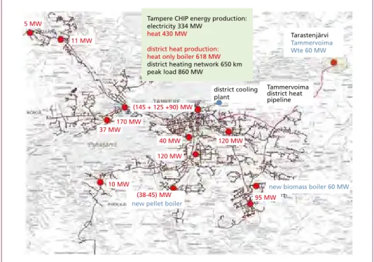
Project implementation was initiated by the revised Finnish Waste Act of 2011 that prohibited, starting from 2016, the disposal of biodegradable and other organic waste to landfills. As the result of the new legislation, Tampere Regional Solid Waste Ma- nagement Ltd decided to start planning a waste incineration solution together with Tampere Power Utility. The aim was to find a site for the new plant in the area covered by the Tampere district heating network because district heating load is large enough to fully utilize the heat of waste incineration even in summer time. The Tampere dis- trict heating network includes 5,700 buildings and more than 230,000 residents live in houses with district heating. The market share for district heating in Tampere is 92 %, and the annual consumption of district heat is 2,200 GWh.
Based on the results of environmental impact assessment, the Tarastenjärvi area was chosen as the site location. Twelve kilometres of new district heat pipelines had to be constructed between the site and the city centre of Tampere. The landfill area of the
Waste Incineration
waste management company is located at Tarastenjärvi, which made it logistically a good site for the new facility. No changes to waste transport systems were needed, and the waste management company is responsible for waste receiving station and weighing services utilising the existing infrastructure as previously.
Figure 1: Tampere district heating network
Tampere CHIP energy production:
electricity 334 MW heat 430 MW district heat production:
heat only boiler 618 MW district heating network 650 km peak load 860 MW
11 MW 5 MW
37 MW170 MW
10 MW
40 MW 120 MW
120 MW
95 MW (38-45) MW
new pellet boiler
new biomass boiler 60 MW (145 + 125 +90) MW
district cooling plant
Tarastenjärvi Tammervoima Wte 60 MW
Tammervoima district heat pipeline
In 2011, a joint undertaking by the name of Tammervoima Oy was established with the task of overseeing the construction of a new waste incineration plant in Tampere.
The stakeholders for this new company are Tampere Power Utility (51 %) and Tampere Regional Solid Waste Management Ltd (49 %). The aim for waste incineration was that it must promote materials recycling, and only the portion of the municipal solid waste (MSW) that is invalid for materials reuse was to be directed to energy production. The reliable grate technology was chosen for the new plant, and incineration capacity was set to 160,000 tonnes per year. The collected waste comes from the 17 municipalities and 500,000 residents in the Tampere region for a total of 130,000 tonnes per year, with an additional 30,000 tonnes from 150,000 residents in Central Finland. The munici- pal waste management company in the Jyväskylä region was chosen to complement waste collection so that we were able to construct an adequately large facility to ensure cost-effectiveness for incineration. The Tampere WtE plant is currently incinerating the MSW produced by 650,000 residents, along with small amounts of hospital waste (2 %) and commercial waste lots (5 %). The maximum waste transporting distance to the new plant is approximately 150 km.
Waste Incineration
Figure 2: Tampere region waste collection area, 500,000 residents
1.2. The Tampere WtE construction project completed on a tight schedule
Preparations for the project started in 2011 with an environmental impact assess- ment. The result of the environmental analysis clearly supported the Tarastenjärvi area as the best location for the WtE plant, even the energy company wanted the plant to be closer to the existing district heat network. The license application pro- cesses for the incineration plant and the zoning for the power plant site advanced quickly in 2012 and 2013. There were no complaints or appeals that could have imposed delays for the project. In addition, Tammervoima received the Finland’s Best Award for the environmental impact assessment (EIA) in 2012, which helped promote the project’s public image.
Once the building permit for the power plant was granted in the summer of 2013, construction could start right away in early September. The plant was ready for production in two years and the total cost came to 111 million EUR. By using the EPCM (Engineering, Procurement, and Construction Management) project mo- del, the construction project was divided into 54 separate procurement packages and contract work assignments. During the construction phase, a total number of 2,300 workers were employed and the entire project size was 350 person-workyears on site.
Parkano
Virrat
Ruovesi
Mänttä- Vilppula Ylöjärvi
Ikaalinen
Hämeenkyrö Sastamala
Nokia
Tampere
Pirkkala
Vesilahti Lempäälä
Kangasala
Pälkäne Orivesi
Juupajoki
Tampere Region
Tampere regional solid waste management provides waste management services within the 17 owner municipalities in the southern part of Finland
Waste Incineration
The first batches of waste were incinerated as early as September 2015, and the com- missioning of the whole plant and the warranty tests were highly successful during the last quarter of 2015. The new WtE plant received acceptance for commercial produc- tion right at the start of 2016, at the same time the disposal of waste to landfills was forbidden in Finland.
Figure 3:
Tampere WtE plant’s building period Sept 2013 – Dec 2015, Status in Summer 2014 – on the background the waste pre- treatment plant and closed land- fill area
1.3. Layout and technical data
As our EPCM consultant, ÅF Consult Oy was responsible for the plant’s design, construction supervision, and commissioning. The building’s layout is very traditi- onal and compact. The flue gas cleaning system is located outside the boiler house.
Figure 4:
January 2016, plant already in commercial production – in the foreground the separate office building and visiting auditorium
Waste Incineration
The turbine hall is built under the boiler facility’s horizontal part to save cubic content.
The plant’s electrical systems are located next to the turbine hall so that the 20 kV medium voltage switchgears and stand-by supply system on the lowest floor. The low voltage equipment is on the second floor and the instrumentation and automation systems on the third floor.
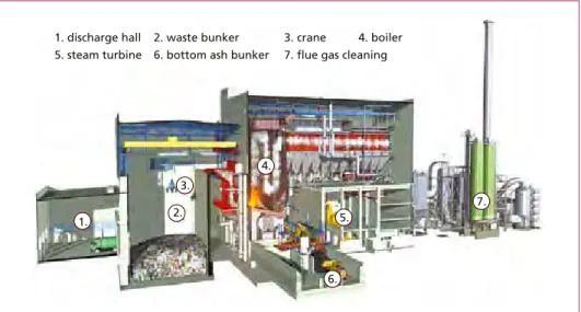
7.
1. 2.
3.
4.
5.
6.
1. discharge hall 2. waste bunker 3. crane 4. boiler 5. steam turbine 6. bottom ash bunker 7. flue gas cleaning
Figure 5: Tampere WtE plant layout
The aims for the plant design were flexible adjustment features for electricity and heat production, as well as high usability for the hole facility. In addition to the main heat exchanger, there are also two reduction heat exchangers that enable continuing incineration at full capacity even when the turbine facility is out of use. The district heating system has a heat accumulator to add flexibility to district heat production during fluctuating district heat consumption at different times of the day. The plant is also connected to two different substations to guarantee the electricity supply.
Table 1: Building volumes and production capacity of the Tampere WtE plant Site and building
Land area of the site 32,000 m2 Building volume 144,260 m3 Total floor area 9,900 m2 The high of the boiler house 46 m Production capacity electricity/heat CHP operation net 12.5 MW / 45 MW Heat only mode net 0.5 MW / 57 MW Internal electricity load 1.6 MW Heat storage 2,300 m3 / 100 MWh 15 MW
As a technical innovation, the plant fea- tures utilising the condensation water of the flue gas condenser in the power plant processes and flue gas cleaning system.
The rest of condensation water is purified for the extra district heat water and fed into the district heat network via the heat accumulator. The plant uses an extremely small amount of clean water and it is only used for boiler water.
The Tammervoima waste-to-energy plant‘s building and technical data are listed below.
Waste Incineration
1.4. Energy production and ashes
The production targets set for the plant have been reached very well. In the first two years of operation, waste incineration usability has been at a level of 99.0 to 99.5 % with annual operation of 8,050 to 8,100 hours. The plant has had one yearly summer revision with a duration of three to four weeks. The plant’s annual production has been raised with 5 % overload operation to the level of 470 GWh, and in 2018 the received amount of waste will be 170,000 tonnes.
Table 2: Technical data of the main components of the Tampere WtE plant Boiler Steinmüller Babcock Environment GmbH Number of units 1 unit / grate system, boiler and steam generator
Throughput per unit 20 Mg/h
Throughput total plant 160,000 Mg/y Design heating value of the waste 10.5 MJ/kg
Thermal capacity 58.5 MW
Grate system air cooled forward moving grate/surface 73 m2
Type of boiler 4-pass horizontal
Production of steam per unit 73.8 t/h
Steam pressure 42 bar
Steam temperature 402 °C
Flue gas cleaning Lühr GmbH
Procedure Semi dry system | scrubber, upper and lower circulation | ESP and SNCR Flue gas volume flow 110,000 Nm3/h humid
Turbine – Generator 16 MVA MAN Energy Solutions SE
Type of turbine District heating turbine with one stage DH-exchanger Steam parameters 40 bar(a) | 400 °C | 22,0 kg/s
Cranes – 2 units Kone Cranes Oyj Charging capacity, nominal per unit 46.8 tonnes/h
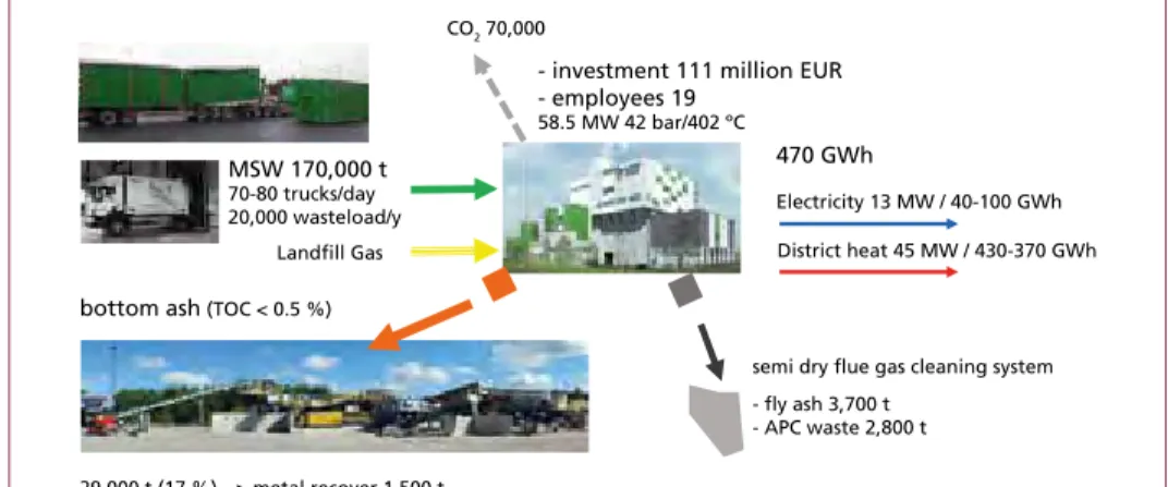
- investment 111 million EUR - employees 19
58.5 MW 42 bar/402 ºC CO2 70,000
470 GWh
Electricity 13 MW / 40-100 GWh District heat 45 MW / 430-370 GWh
semi dry flue gas cleaning system - fly ash 3,700 t
- APC waste 2,800 t
29,000 t (17 %) --> metal recover 1,500 t bottom ash (TOC < 0.5 %)
MSW 170,000 t 70-80 trucks/day 20,000 wasteload/y
Landfill Gas
Figure 6: Tampere waste-to-energy concept
Waste Incineration
The utilisation of bottom ash from the incineration process has also been resolved al- ready during the first year of plant operations. After metals have been recovered from the bottom ash, the remaining ash is sieved. The separated mineral fractions are utilised as auxiliary material in concrete and the coarser fractions in foundation engineering for street construction. In the future, it will be possible to resolve salts and metals also from the fly ash, which will raise the materials utilisation rate of the ashes produced in the waste incineration process to 97 %. Air pollution control residue (APC waste) is taken to a landfill.
1.5. Emissions
Thanks to the efficient flue gas cleaning system, the plant’s atmospheric emissions have been realised at a very low level. Compared to the plant’s environmental license, the realised emissions in 2017 have been only 1 % of the allowed discharge standard excluding nitrogen oxides and carbon monoxide. The level of NOx emissions is 66 % and that of carbon monoxide is 16 % of the allowed discharge standard. The plant’s carbon dioxide emissions are 70,000 tonnes per year. The calculations are based on the Finnish CO2 default emission factor 40 t/TJ for municipal solid waste.
Environmental Measured New BAT-AEL Parameter permit 2013 value Realisation for existing
plants
mg/Nm3 mg/Nm3 % mg/Nm3
NOx 200 132 66 50 – 180 (SNCR)
SO2 50 0.3 0.6 5 – 40
Dust 10 0.1 1.0 < 2 – 5
CO 50 8.0 16 10 – 50
TOC 10 0.1 1.0 < 3 – 10
HCl 10 0.1 1.0 < 2 – 8
HF 1 0.001 0.1 < 1
Table 3:
Tampere WtE plants emission versus the environmental permit and the new BAT
The flue gas purification equipment was built by utilising the best available technolo- gy (BAT) while also taking into account the new BREF Waste Incineration Draft. In Finland, the NOX limit for the new BAT-AEL for existing plants is likely to be lowered to 150 mg/Nm3 (SNCR) based on the environmental licence for the new plant to be constructed in Western Finland. The operation of the Tampere plant is already in compliance with the new flue gas discharge standards enforced in the future. As the environmental license is updated in the future, it is likely that the only investment for the emission measurement equipment is real-time Hg measuring system.
2. Waste and energy management at the Tampere WtE plant 2.1. Organisation of operations
The production operations of the waste incineration plant are carried out in a cost- effective manner by utilising its owners’ core competencies. The waste incineration company does not have its own staff, it purchases all the resources and services from
Waste Incineration
its owners or from external service providers. Tampere WtE business concept is to incinerate waste at cost price and to produce low-priced district heat and electricity for energy company.
The resources and services produced by the owners can be summarised as follows:
Services produced by the waste management company:
• Waste transport and collection
• Waste acquisition and intermediate storing if required
• Waste classification and weighing services
• Operation of the waste pretreatment plant
• Reclamation of materials in bottom ash and recovery of metals
• Public relations and consumer advice on waste management issues Services produced by the energy company:
• Power plant running and maintenance
• Company’s administrative and financial services
• Environmental reporting and reports to authorities
The plant has 19 employees, with 12 operators working in pairs in 12-hour shifts. The Plant manager is responsible for production operations and the Maintenance manager take care of maintenance whit four maintenance technicians. The cleaning services and maintaining the outside areas are subcontracted. The disposal services for the fly ash and APC waste are also outsourced.
Presentation at the power plant are handled by the owner companies’ communications staff. 10,000 guests have already visited the new Tampere WtE plant in its first two years of operation.
2.2. Developing the waste collection system increases recycling and accelerates incineration
As the waste management company is responsible for the acquisition of waste-derived fuel and for its quality, it is in the best interest of the company to improve the heating value of waste and to decrease the number of objects unfit for incineration. In Tampere, separate collection of catering waste and bio-waste has been implemented more than twenty years ago in all buildings with more than five apartments. To increase recyc- ling rates, 5,500 containers for recyclable glass and metal have been distributed free of charge to housing cooperatives since 2016 in the Tampere region. Separate collection of plastic in residential buildings started in 2017.
Quality control for waste reception has been enhanced also at the weighing station by directing 30 % of the arriving waste loads to the new pretreatment plant where metals and pieces of concrete is separated and the remaining waste is crushed. By developing
Waste Incineration
its collection system, the local waste management company has increased its recycling rate by nearly 5 % in the past few years. At the same time, the amount of incineration bottom ash has decreased by 10 % and its TOC has stabilised at a level of 0.5 % thanks to the improved quality of waste and efficient incineration process.
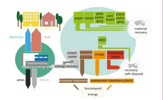
Figure 7: Tampere waste collection system
The quality of waste fuel has been high enough to avoid using oil as support fuel except when starting up and shutting down the plant. The annual average heat value for waste has stabilised at a level of 11.3 MJ/kg. The high heat value has limited the amount of received waste in summer time, and the design value of 20 t/h for incineration capacity has not been reached.
1 2 3 4 5 6 7 8 9 10 11 12
10.4 10.6 10.8 11.0 11.2 11.4 11.6 11.8 12.0
heating values of waste MJ/kg
months
Figure 8:
Monthly heating values of waste
Tammervoima waste-to-energy plant
paper metals
electricity heat
ashes metals
energy biocompost
wastewater treatment plants biowaste treatment
sludge hazardous waste biowaste
mixed waste
recovery/
safe disposal material recovery WEEE
energy recovery
glass packa-
ging card- board
plastic packa- ging
Waste Incineration
2.3. Waste incineration benefits for energy company
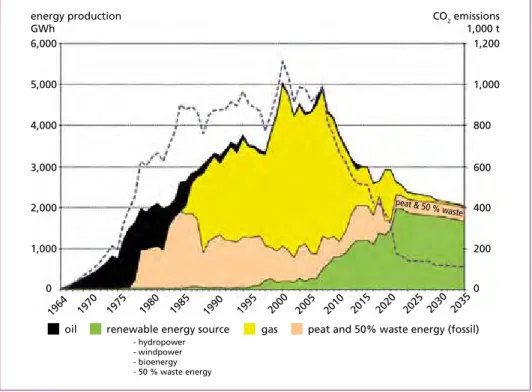
Tampere has been one of the biggest users of gas in Finland since the 1990s. As the taxation for gas has become eightfold in the past decade, using gas has become a threat to district heat competitiveness. In addition, the trend in Finland is to free the heating market by removing the municipal right of obligating parties constructing new buil- dings to join the district heating network.
Waste incineration is replacing the use of fossil fuels in Tampere, especially natural gas, thus lowering district heat production costs. In the same time the greenhouse gas emissions in energy production has decreased by ten percent. The production of rene- wable energy in Tampere has also increased by twenty percent due to waste incineration.
gas peat and 50% waste energy (fossil) peat & 50 % w
aste
oil renewable energy source energy production
GWh
0 1,000 2,000 3,000 4,000 5,000 6,000
CO2 emissions 1,000 t
0 200 400 600 800 1,000 1,200
1964 1970 1975 1980 1985 1990 1995 2000 2005 2010 2015 2020 2025 2030 2035 - hydropower
- windpower - bioenergy - 50 % waste energy
Figure 9: Tampere energy production and CO2 emissions
The flexible and fast production controlling possibilities in a modern waste incineration plant has brought new opportunities for energy production optimisation for energy companies. Waste incineration plant has no longer to be of a production unit running fixed base loads. The production plan of the Tampere WtE plant is optimised daily and per hour in the energy management system as part of a larger production complex while taking into account the market conditions for fuel and electricity. Profitability at the Tampere WtE plant has significantly been increased by heat accumulator when the cost of electricity has been low or increased heat production has been required in peak load situations.
Waste Incineration
In the future, the performance of the production process could be further improved by adding a heat pump to lower the return water temperature of the district heat, thus also increasing the production of the existing flue gas scrubber. The profitability of electricity production could additionally be improved by investing in electric accumulators that would enable the WtE plant to participate in the frequency electricity market.
3. Summary
The local waste management company and the energy company in Tampere region have managed to construct, in a Public-Private Partnership, an efficient energy recovery concept for municipal solid waste. This concept provides an annual added value of 30 million euros and the waste fees are the lowest in Finland. The waste management company has provided residents with thorough waste sorting counselling. 500,000 re- sidents are now source separating waste in homes. Only one percent of the municipal solid waste is disposed to landfills in the Tampere region.
In the Tammervoima plant, one hundred percent of the waste energy is recovered with the operational efficiency of more than 95 %. Waste incineration has decreased local CO2 emissions by 60,000 tonnes annually and it has compensated for 600 GWh of gas export from Russia. Today, waste-to-energy covers 15 % of the district heating and electricity production in Tampere.
Contact Person
Dipl.-Ing. Mika Pekkinen Tammervoima Oy Chief Executive Officer Hyötyvoimankuja 1 33680 Tampere FINLAND
Phone: 00358 - 50 599 43 00
Email: Mika.Pekkinen@sahkolaitos.fi
Weld overlay for boiler protection at highest quality From our state of the art workshop in Portugal
MARTIN plants and technologies
Bibliografische Information der Deutschen Nationalbibliothek Die Deutsche Nationalbibliothek verzeichnet diese Publikation in der Deutschen Nationalbibliografie; detaillierte bibliografische Daten sind im Internet über http://dnb.dnb.de abrufbar
Thiel, S.; Thomé-Kozmiensky, E.; Winter, F.; Juchelková, D. (Eds.):
Waste Management, Volume 8 – Waste-to-Energy –
ISBN 978-3-944310-42-8 Thomé-Kozmiensky Verlag GmbH
Copyright: Elisabeth Thomé-Kozmiensky, M.Sc., Dr.-Ing. Stephanie Thiel All rights reserved
Publisher: Thomé-Kozmiensky Verlag GmbH • Neuruppin 2018 Editorial office: Dr.-Ing. Stephanie Thiel, Dr.-Ing. Olaf Holm,
Elisabeth Thomé-Kozmiensky, M.Sc.
Layout: Janin Burbott-Seidel, Ginette Teske, Roland Richter, Cordula Müller, Sarah Pietsch, Gabi Spiegel, Lena Bischkopf
Printing: Universal Medien GmbH, Munich
This work is protected by copyright. The rights founded by this, particularly those of translation, reprinting, lecturing, extraction of illustrations and tables, broadcasting, micro- filming or reproduction by other means and storing in a retrieval system, remain reserved, even for exploitation only of excerpts. Reproduction of this work or of part of this work, also in individual cases, is only permissible within the limits of the legal provisions of the copyright law of the Federal Republic of Germany from 9 September 1965 in the currently valid revision. There is a fundamental duty to pay for this. Infringements are subject to the penal provisions of the copyright law.
The repeating of commonly used names, trade names, goods descriptions etc. in this work does not permit, even without specific mention, the assumption that such names are to be considered free under the terms of the law concerning goods descriptions and trade mark protection and can thus be used by anyone.
Should reference be made in this work, directly or indirectly, to laws, regulations or guide- lines, e.g. DIN, VDI, VDE, VGB, or these are quoted from, then the publisher cannot ac- cept any guarantee for correctness, completeness or currency. It is recommended to refer to the complete regulations or guidelines in their currently valid versions if required for ones own work.