As your expert for refractories we create innovative solutions for all industries. For more than 80 years.
Worldwide. The closeness to our customers has made us strong. We focus on the specific requirements of our business partners and provide customized complete solutions. We do not know any limits in Refracotries. In this sense we are always willing to be at your service.
in Waste-to-Energy
Thermische Anlagen Bazenheid, Switzerland Refractory Lining Boiler 1
osion
Fouling Textures and Micro-Milieus Determine High Temperature Chlorine Corrosion in Power Plants
Fired with Waste or Biomass
Wolfgang Spiegel, Marie Kaiser and Werner Schmidl
1. Standard method for handling corrosion samples ...552
2. Reading fouling textures ...553
3. Micro-milieus of high temperature chlorine corrosion ...555
4. Examples ...557
5. Literature ...559
Due to the highly aggressive chemical environment resulting from the incineration of waste and biomass corrosion on heat exchanging tubes in power plants is quite common.
Therein corrosion leads to a restriction in energy efficiency, life time and availability of power plants, which is still of high economic importance for plant manufacturers and operators.
Especially high temperature chlorine corrosion of boiler tubes in such power plants is a well-known phenomenon. Chloridic salts of alkali-elements (K, Na), also earth- alkali-elements (Ca, Mg) and heavy metals (Zn, Pb) are frequent root causes for this kind of corrosion.
The load and chemical species in the flue gas, the temperature level at the tube surface and the heat flux set conditions which result in a specific type and dynamic of corrosion attack [1, 4, 5, 6].
Despite of these well-known chemical and thermal facts further conditions are of relevance to get high temperature chlorine corrosion started on a tube surface. These conditions refer to textural properties. High temperature chlorine corrosion depends on the formation of a kind of cover on the tube surface, for example a thin layer of fouling on the clean tube surface and/or a scale layer.
After chlorine corrosion has started, the first corrosion products, chlorides, sulphides, sulphates and oxides form a fouling growing from the tube side and will interact with the fouling components coming from the flue gas side. Whilst maturing, formation and growth of the fouling, the corrosion front will become a reaction zone with a certain micro-milieu encapsulated from the flue gas.
The thermal, chemical and textural conditions of that micro-milieu determine the type, mechanism and dynamic of the corrosive wear. As a pile of layered structures
osion
the influencing volume of that encapsulated micro milieu starts even in the tube alloy material with unchanged alloy, followed by the most inner front of corrosion attack starting at grain boundaries. Adjacent follow several layers of corrosion products in- tercalated with salts and finally layers of fouling from flue gas components.
The texture formed by these layers changes with ongoing corrosion and mechanical, chemical or thermal impact, resulting in different dynamics of corrosion on a local scale.
To unveil the respective corrosion processes and to understand the causes and mecha- nisms of corrosion detailed investigations of the corrosion layers are necessary. The authors recommend standardized conditions for handling and preparation of samples.
Destructive testing of corroded tubes or probe-based corrosion tests typically focus on the layered structures and on the corrosion front to define the micro-milieu of formation, using microscopic measures.
Like sediments can be read by geologists to reclaim a deposition history, these layered structures and their textures deliver information to understand causes, mechanism and important conditions of high temperature chlorine corrosion. This paper gives recom- mendations for sample handling and preparation as well as examples of interpretation of textural information deriving from microscopic techniques.
1. Standard method for handling corrosion samples
The authors report and discuss on corrosion in power plants based on investigations of damage-samples or probe installations. During the last decades thousands of objects have been handled at the CheMin labs, which led to a wide range of experience and know-how.
In order to ensure a high level of reliability and comparability of the results, the compa- ny investigates tube material affected by corrosion with a specific procedure, which is based on experience and internal quality requirements. This CheMin standard method for corrosion investigations includes:
• The tube to be investigated should be untouched after shut down, including espe- cially no cleaning and mechanical harm.
• The extraction procedure of tube material by company staff preserves all corrosion phenomena and minimizes the mechanical and thermal impact during cutting and transportation onsite.
• The exact position of the extracted sample within its orientation in the structural element is documented and photographed.
• After a transportable size of an onsite-sample is reached, further impact of humidity is stopped by packaging.
• The transport from the plant site to the lab should be handled by company staff. In cases where this is not possible due to logistic conditions, special transportation equipment is used.
osion
• At the lab the sample and the corrosion phenomena are documented and photo- graphed in detail.
• Regarding the questions to be answered for the client, the sample is evaluated by corrosion experts to select the most promising positions for further investigations on a local scale.
• Selected positions are cut, embedded in resin and polished in order to get an un- disturbed view on the whole corrosion sequence of alloy, corrosion front, corrosion products and fouling. This procedure is essential in order to preserve all informati- on. Especially all steps of preparation have to be free of any water impact, in order not to bring salts into solution. Such, the corrosion can be investigated spatially resolved by light microscopy and scanning electron microscopy.
• The microscopic investigations start with the identification of phenomena on a larger scale and will continue towards smaller scales. Texture, chemical composition and chemical distribution of specific elements are of relevance as well as species de- termination by spot analysis with an energy dispersive x-ray analyser (SEM-EDX).
• Additionally, mechanical separated parts of the sample like fouling or corrosion products are examined by bulk chemical investigation (XRF, wet chemistry), to check the presence of specific components like carbonates or ammonium salts or to parallelize information of bulk chemical composition from fouling samples extracted separately from the boiler.
• All findings from the above described investigation steps are merged in order to identify the type, cause and mechanism of corrosion for each sample or damage.
• All findings are classified into categories like common, typical, rare, new, or special for a specific influencing condition, connected with chemical, mechanical or ther- mal impact.
2. Reading fouling textures
To read fouling textures in a precise way some key facts have to be considered:
• The investigation of fouling textures of corrosion processes is a post mortem analy- sis. Any corrosion process was frozen during shutdown. Also there is no timestamp at any specific textural condition. But, the relative position of a textural condition in the whole process (first adjacent to the corrosion front, second, third ….) can be extracted in many cases.
• The starting condition of a fouling texture is a new tube or protective coating be- fore first operation. Also the virgin material texture, chemistry and metallurgy are important preconditions for any upcoming corrosion.
• First operation shifts the alloy and the simultaneous formed scale to a specific temperature level and heat is transported through the system. This imprints a spe- cific thermal expansion of the tube and a differing thermal expansion of the scale,
osion
as well as a thermal gradient inside the scale and the tube. This will induce stress into the two components, tube and scale, and possibly weaken the fixation of the scale on the tube surface.
• Firing solid fuels like waste or biomass will upload the flue gas with solid, molten and gaseous components. Due to flow conditions the tube surface will get in con- tact with solid and molten particles. Depending on surfaces stickiness a particle can be deposited and can become part of the fouling. Also gaseous components contribute to the fouling by desublimation and/or condensation at local cooling of the flue gas and saturation of salt species or by gas-solid reactions (i.e. sulphation).
All fouling formation processes cover the alloy and the scale, lower the heat flux and local temperatures inside the alloy, the scale and the fouling. At the same time, with growing fouling thickness the surface temperature of the fouling rises.
• Further, with growing thickness of the fouling the formerly deposited parts of the fouling tend to form a micro-milieu with specific textural properties. Especially reduction of open porosity and formation of caverns support proper conditions for high temperature chlorine corrosion. Main processes in this pastry bakery are solid-solid reactions of salts, state transitions (solid to liquid and vice versa), eva- poration of salts (partial pressure) and desublimation. Gas-solid reactions occur, in which oxygen, chlorine and sulphur are reacting with fouling components, corro- sion products and the alloy. Also grain coarsening and local enrichment of specific components happen due to their thermodynamic properties.
• With changing operational conditions like fuel chemistry, firing conditions, or de- creasing boiler performance during an operational period the micro-milieu will create higher or lower corrosion performance. Maturing effects will stabilise the pastry in most cases. The typical time scale of hundreds to thousands of hours and the ongoing heating enables the corrosion processes to behave flexible and to keep reactions running.
• Each shutdown freezes more or less suddenly the fouling and stops almost all inclu- ded processes. This gives an unavoidable final impact to some textural conditions, like segregation of melts, new cracks due to shrinkage and brittleness and also impact by outage air humidity.
The investigation of damage tube samples is not only a post mortem analysis but typi- cally also affected by unknown past conditions:
• In most cases the history of operational conditions during lifetime of the damaged tube are of limited transparency.
• Findings from damage tube samples about mechanism(s) and cause(s) of corrosion refer in a strict sense to conditions of boiler operation before last shutdown. The whole sequence of relevant operational conditions during lifetime of the tube and evolution of the corrosion damage possibly includes a complex chain of causes rela- ted to changing chemical, thermal, mechanical and textural conditions during one or even several operational periods. This chain can’t be decoded by investigation of a damage sample in any case.
osion
• Especially losses of corrosion products and/or fouling during lifetime of the da- maged tube due to falling off or cleaning have a strong impact on the texture and the micro milieu. From investigations of damage tube samples it remains unclear in most cases if all corrosion products are preserved or not.
In contrast to the unavoidable post mortem character of the sample the unknown past conditions are avoidable, if the damage sample is not derived from a boiler tube but from a probe tube. A probe tube can be regarded as a case of designed and controlled damage. The step to proceed from damage samples cut out of boiler tubes towards da- mage samples cut out of probe tubes, which have been installed inside a boiler, enables higher transparency of the processes and accuracy of information. This is a significant upgrade for a better understanding of corrosion processes.
CheMin has developed several kinds of probes. With this method of a defined time range examination the unknown past can be eliminated. Most relevant for fouling and corrosion investigations are the so called temperature-range-probes (TRP). The following publications give detailed information: [1, 2, 3]. These probes are temporarily operated as heat exchanging components, like an additional part of the boiler. The probe will be affected by the same conditions like the water walls and super heaters according to the installation position of the probe. It collects agglomerates and performs the same fouling and corrosion processes like the surrounding boiler tubes.
One big benefit of TRPs is the freely selectable time window of operation. Beginning and ending of operation of the TRP is independent from shutdown. The time window can be selected in relation to specific operational conditions (fuel or firing) or with interest to specific questions (i.e. fouling formation and corrosion mechanism after a shorter or longer time period). The time window may vary from some hours up to several months.
The TRPs were designed as a one-way-probe for a robust, quick and frequent use in any kind of boiler or other hot processes. High variability of size, materials and positions inside the boiler support a wide range of applications.
The standard method for corrosion investigation as described in chapter 1 for damage tube samples is relevant for TRPs in the same way.
3. Micro-milieus of high temperature chlorine corrosion
High temperature chlorine corrosion is the most important corrosion process in power plants fired with waste or biomass. Also an essential type of corrosion processes is salt melt corrosion. But the impact towards damages and economical disadvantages of salt melt corrosion is much lower than that of high temperature chlorine corrosion. A further type of corrosion is deliquescent corrosion, which is of relevance for the colder parts of a boiler, e.g. ECO, LUVO, flue gas cleaning.
All these corrosion types in power plants are related to the formation of fouling. But not all kinds of fouling will induce one of these corrosion types. A fouling consisting
osion
of towards these corrosion processes inert components only, like oxides, with low porosity and no desublimation of salts in pores, will behave like a refractory layer.
The only effect of this kind of fouling is a reduced heat flux. In such cases the access of HCl, SO2 and O2 from the flue gas towards the surface of the alloy is limited and no corrosion process will start.
The following consideration of micro-milieus will focus on high temperature chlorine corrosion, because it shows a wide variety of textural phenomena.
In contrast, salt melt corrosion is characterized by one dominating phenomenon:
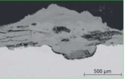
pitting into the alloy with a quite sharp and trans-crystalline corrosion front (Figure 1). The same morphology can be reached by deliquescent corrosion, which is not high temperature corrosion but induced by water-electrolyte with typical dew point corrosion phenomena (figure 2).
500 µm 500 µm
Figure 1: A salt-melt corrosion attack digs out a dip of the material surface (temperature approx. 500 °C);
after a certain time the chemical potential of the primary salt melt is exhausted and the process stops
Figure 2: Deliquescent corrosion attack caused by Ammonium-Chloride- Bromide leads to a similar optical result like in Figure 1; a local pitting excavated in carbon steel at a tem- perature level around 95 °C
In general, high temperature chlorine corrosion phenomena are characterised by seve- ral gas-solid and gas-gas reactions and state transitions. The relevant gaseous species diffuse into the porous structure of the fouling and of the corrosion products. If this porous space is connected to the corrosion front of the material corrosion reactions are possible. Each type of reaction forms textural indications. Some relevant indications are (figure 3 relates to iron-based alloys):
• Intercrystalline corrosion front with a depth of some 10 to some 100 micron in the alloy see figure 3 (a).
• Formation of some 10 to some 100 micron thick layer of iron chloride with low porosity, see figure 3 (a, b and e).
• Formation of iron sulphides with low porosity in vicinity to iron chlorides (b).
• Formation of fine iron oxide pigments in the porous structure of the fouling, libe- rating gaseous chlorine species for chlorine looping, see figure 3 (b).
osion
• Formation of iron oxide layers with high porosity and a puff pastry texture, see figure 3 (c).
• Mixed salts of alkalis and heavy metals (chlorides with some sulphate components) inside the pastry texture, acting as a chlorine depot, see figure 3 (c and d).
• Redistribution of salts at specific temperature areas inside the fouling, forming a gas barrier (d and e).
• Crystal growth and sulphation reaction of chloridic salts (f).
50 µm 500 µm
200 µm 200 µm
100 µm 200 µm
In general, high temperature chlorine corrosion needs a micro milieu free of oxygen in the gas phase and the presence of gaseous chlorine. It is still a matter of research to estimate and understand the beginning of the process, i.e. proper starting conditions.
Anyhow with matured fouling these conditions are more likely available, presumably after some hours of operation.
4. Examples
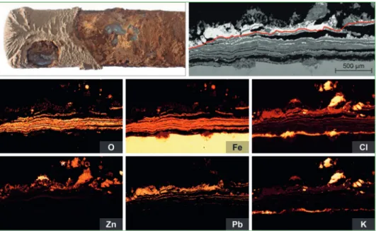
The examples in figure 4 and 5 belong to TRPs investigated by SEM-EDX, including their respective element maps. The examples are selected to illustrate the reading of textures and the complex variety of phenomena of high temperature chlorine corrosion.
Any systematic consideration of specific conditions is not included (i.e. kind of fuel, firing, part of the boiler, alloy, heat flux, medium temperature, flue gas temperature).
The figure text describes the textural highlights.
Figure 3:
All figures show stratigraphic information from deposition of a salt-ash-covering on heat exchanging surfaces and a cor- rosion layer
a) Intercrystalline corrosion attack on a plain carbon steel surface. The 10-micron chloride layer swallows little perlite grains of the steel and digests them into oxides.
b) Under certain conditions (absence of oxygen) an intermediate step from iron chlorides to iron oxides can be a sulfidation with the formation of iron sulfide (yellow colour in light microscopy).
c) Multi-layer scaling of a puff pastry type. Very thin sheets of oxide layers are separated by salt interlaces and capsuled by a salt-ash- formation
d) A layered iron oxide formation with lead- chloride-plumes form a mushroom-texture.
e) A four-horizon corrosion scaling is sealed from top by the growth of a lead-chloride- crystal salt barrier (bright colour).
f) Lead-sulphate-crystals (again bright colour) can also form idiomorphic structures (like in a geode) when they have enough time and temperature to recrystalize
osion
Figure 4: Corrosion scales of a Puff-Pastry-Type; after only 300 h of exposition to firing conditions a strong stratification has evolved with thin iron oxide layers and intercalated lead salts;
the red line marks the former tube surface; at the corrosion front potassium chlorides serve first as chlorine deliverant for active oxidation and at the fireside together with lead and zinc as a sealing for closed shop conditions
Figure 5: Salt-ash-deposition of a glass-marble-type (continuation following page)
osion Figure 5 – continuation: Salt-ash-deposition of a glass-marble-type; after 800 h of exposition slag spheroids have been deposited and corrosion scales have evolved; the red line marks the former tube surface. The calcium-aluminium silicate marbles are covered and glued together by a zinc-potassium sulphate-salt with a chloridic component; it first appeared as chloride and was sulphated; again at the corrosion front iron-chlorides do their destructive job
Both examples illustrate the potential of TRPs to investigate the cause and mechanism of corrosion in an undisturbed, transparent and clear way. This high quality of informa- tion is a proper basis to mitigate corrosion by optimisation of operational conditions and/or materials.
In many cases of optimisation a stepwise approach with a sequence of TRPs is of high value.
5. Literature
[1] Kaiser, M., Spiegel, W. (2017): Thermochemische Prozesse verstehen und verbessern. In Beck- mann, M. und Hurtado, A. (Hrsg.): Kraftwerkstechnik 2017 Strategien, Anlagentechnik und Betrieb, page 329-341. Available on www.chemin.de
[2] Kaiser, M.; Schneider, D.; Brell, J.; Kuttner, T.; Spiegel, W. (2016): Temperature-Range-Probe (TRP): Korrosion erkennen, vermindern, vermeiden. In Beckmann, M. und Hurtado, A. (Hrsg.):
Kraftwerkstechnik 2016 Strategien, Anlagentechnik und Betrieb, page 381-393. Available on www.chemin.de
[3] Kaiser, M., Schneider, D., Brell, J., Molitor, D., Kuttner, T.: Effizienzsteigerung – Anwendung der Temperature–Range-Probe zur Optimierung der Werkstoffwahl in Kraftwerken. In: VGB Powertech, Vol. 10/2015, page 53-58. Available on www.chemin.de
[4] Magel, G. (2017): Get to know the Corrosion Mechanisms in Waste-to-Energy-Plants. IRRC Wien 2017. Available on www.chemin.de
[5] Müller, W., Schneider, D., Kaiser, M., Brell, J., Spiegel, W. and Pohl, M. (2014): Fuel leaflets for the prevention of negative impact on the boiler from minor fuel constituents. VGB PowerTech, Vol. 7/2014, page 76 - 81. Available on www.chemin.de
[6] Spiegel, W.; Kaiser, M.; Magel, G.; Schmidl, W. (2018): Relevant Thermochemical Processes in Biomass Fired Power Plants. IRRC Wien 2018. Available on www.chemin.de
Contact Person
Dr. rer. nat. Wolfgang Spiegel Managing Director
CheMin GmbH
Am Mittleren Moos 46 A 86167 Augsburg
GERMANY +49 821 7483940 w.spiegel@chemin.de
Dorfstraße 51
D-16816 Nietwerder-Neuruppin
Phone: +49.3391-45.45-0 • Fax +49.3391-45.45-10 E-Mail: order@vivis.de
Waste Management – Waste-to-Energy
Rüdiger Margraf
Waste Incineration
Figure 7:
Rough scheme dry hydration CaO Dosing balance
H2O
Dry hydrator CaO
CaO Silo
Ca(OH)2 Ca(OH)2 Silo towards lime dosing TIC
Several plants in Germany have been provided with this technology.
Figure 8 shows a plant, realised with a dry hydrator for a Ca(OH)2 production capacity of approximately 3 t/h.
Figure 8: RDF incineration plant EEW Premnitz / Germany As alternative there is the possibility to install the dry hydrator close to the additive
2 can now be injected directly into the reactor without temporary storage in a silo.
Verbrennungs-rost Gewebefilter Elektro-filter Sprüh-
trockner Kamin
Dampf-kessel MüllkranAufgabe-trichter
Müll- bunkerVerbrennungs-luftgebläseAufgabe-vorrichtungPlatten-wände TrogkettenfördererEntschlackung/
Ammoniak-Wasser- Eindüsung
Kessel- entaschung
AbgaswäscherDruckerhöhungs-gebläse Adsorbenssilo
Feuerraum Primär-luft
Figure 3:
Karl J. Thomé-Kozmiensky
Volume 2
WASTE MANAGEMENT
Luciano Pelloni
Waste Management Recycling Composting Fermentation Mechanical-Biological Treatment Energy Recovery from Waste Sewage Sludge Treatment
Thomé-Kozmiensky und PelloniWASTE MANAGEMENT
2
2
Thomé-Kozmiensky und Pelloni
Karl J. Thomé-Kozmiensky
Volume 3 Recycling and Recovery
WASTE MANAGEMENT
Stephanie Thiel
WASTE MANAGEMENTThomé-Kozmiensky und Thiel
3
, Thiel
5
2
Thomé-Kozmiensky und Pelloni
Volume 6 Waste-to-Energy
WASTE MANAGEMENT
Stephanie Thiel Karl J. Thomé-Kozmiensky
6
WASTE MANAGEMENTK. J. Thomé-Kozmiensky & S. Thiel
WASTE MANAGEMENT Volume 2
KARL J. THOMÉ-KOZMIENSKY STEPHANIE THIEL HRSG.
Copyright © 2011 TK Verlag Karl Thomé-KozmienskyAlle Rechte vorbehalten.
Das Einspeisen der Daten in Netzwerke ist untersagt.
WASTE MANAGEMENT Volume 3
KARL J. THOMÉ-KOZMIENSKY STEPHANIE THIEL HRSG.
Copyright © 2011 TK Verlag Karl Thomé-Kozmiensky Alle Rechte vorbehalten.
Das Einspeisen der Daten in Netzwerke ist untersagt.
Waste Management, Volume 2 – 8 • CD Waste Management, Volume 2 and 3
395.00 EUR
save 175.00 EUR
Package Price
Editors: Thomé-Kozmiensky (et.al.)
Waste Management, Volume 5 (2015) ISBN: 978-3-944310-22-0 90.00 EUR Waste Management, Volume 2 (2011) ISBN: 978-3-935317-69-6 CD includes translations in 50.00 EUR + CD Waste Management, Volume 2 ISBN: 978-3-935317-70-2 Polish and German
Waste Management, Volume 3 (2012) ISBN: 978-3-935317-83-2 CD includes translations in 50.00 EUR + CD Waste Management, Volume 3 ISBN: 978-3-935317-84-9 various languages
Waste Management, Volume 4 (2014) ISBN: 978-3-944310-15-2 50.00 EUR
Waste Management, Volume 6 (2016) ISBN: 978-3-944310-29-9 90.00 EUR Waste Management, Volume 7 (2017) ISBN: 978-3-944310-37-4 120.00 EUR Waste Management, Volume 8 (2018) ISBN: 978-3-944310-42-8 120.00 EUR
IRRC IRRC
2
Thomé-Kozmiensky und Pelloni
Volume 7 Waste-to-Energy
WASTE MANAGEMENT 7
WASTE MANAGEMENTK. J. Thomé-Kozmiensky et al.
Karl J. Thomé-Kozmiensky † Stephanie Thiel Elisabeth Thomé-Kozmiensky Franz Winter Dagmar Juchelková
TK Verlag GmbH
order now www. .de 2
Thomé-Kozmiensky und Pelloni
Karl J. Thomé-Kozmiensky † Karl J. Thomé-Kozmiensky † Karl J. Thomé-Kozmiensky † Karl J. Thomé-Kozmiensky †
Volume 8 Waste-to-Energy
WASTE MANAGEMENT
Karl J. Thomé-Kozmiensky † Karl J. Thomé-Kozmiensky † Karl J. Thomé-Kozmiensky †
8
WASTE MANAGEMENTK. J. Thomé-Kozmiensky et al.
Stephanie Thiel Elisabeth Thomé-Kozmiensky Franz Winter Dagmar Juchelková
hardcover with colored illustrations
Bibliografische Information der Deutschen Nationalbibliothek Die Deutsche Nationalbibliothek verzeichnet diese Publikation in der Deutschen Nationalbibliografie; detaillierte bibliografische Daten sind im Internet über http://dnb.dnb.de abrufbar
Thiel, S.; Thomé-Kozmiensky, E.; Winter, F.; Juchelková, D. (Eds.):
Waste Management, Volume 9 – Waste-to-Energy –
ISBN 978-3-944310-48-0 Thomé-Kozmiensky Verlag GmbH
Copyright: Elisabeth Thomé-Kozmiensky, M.Sc., Dr.-Ing. Stephanie Thiel All rights reserved
Publisher: Thomé-Kozmiensky Verlag GmbH • Neuruppin 2019 Editorial office: Dr.-Ing. Stephanie Thiel, Elisabeth Thomé-Kozmiensky, M.Sc.
Layout: Claudia Naumann-Deppe, Janin Burbott-Seidel, Sarah Pietsch, Ginette Teske, Roland Richter, Cordula Müller, Gabi Spiegel Printing: Universal Medien GmbH, Munich
This work is protected by copyright. The rights founded by this, particularly those of translation, reprinting, lecturing, extraction of illustrations and tables, broadcasting, micro- filming or reproduction by other means and storing in a retrieval system, remain reserved, even for exploitation only of excerpts. Reproduction of this work or of part of this work, also in individual cases, is only permissible within the limits of the legal provisions of the copyright law of the Federal Republic of Germany from 9 September 1965 in the currently valid revision. There is a fundamental duty to pay for this. Infringements are subject to the penal provisions of the copyright law.
The repeating of commonly used names, trade names, goods descriptions etc. in this work does not permit, even without specific mention, the assumption that such names are to be considered free under the terms of the law concerning goods descriptions and trade mark protection and can thus be used by anyone.
Should reference be made in this work, directly or indirectly, to laws, regulations or guide- lines, e.g. DIN, VDI, VDE, VGB, or these are quoted from, then the publisher cannot ac- cept any guarantee for correctness, completeness or currency. It is recommended to refer to the complete regulations or guidelines in their currently valid versions if required for ones own work.