221 SNCR for Low NOx Emissions
Waste Incineration
SNCR for Low NO
xEmissions
– Case Study of a Swedish Waste-to-Energy Plant –
Wolfgang Schüttenhelm and Philip Reynolds
1. SNCR process ...222
1.1. Flue gas temperature ...223
1.2. Distance between the injection levels ...225
1.3. Controlling of the SNCR plant ...225
1.4. Fluctuation of base NOx ...225
1.5. Influence of temperature changes ...225
1.6. Influence of residence time ...226
1.7. Choice of reduction agent and its distribution ...229
1.8. Change of steam production ...229
2. Description of the Waste-to-Energy plant and basic design of the SNCR...229
3. First operation experience ...230
4. Investigation...231
4.1. Temperature measurement ...231
4.2. Injection tests ...232
4.3. Analysis of combustion data ...232
5. Conclusions from the first operation and testing period ...232
6. New SNCR solution and introduced measures ...233
6.1. Improvement of the firing control system ...233
6.2. Redesign of the SNCR ...233
6.2.1. Installation of additional levels ...233
6.2.2. Installation of a fast NH3-measurement system at the economiser outlet ...234
6.2.3. Change of the SNCR control mechanism ...234
6.2.4. Injection at two selectable levels at the same time ...234
Wolfgang Schüttenhelm, Philip Reynolds
222
Waste Incineration
6.3. Acceptance Test ...236 7. Summary ...236 8. Literature ...236 All over the world people understand that reducing air pollution is essential to increase health and comfort of people. Nitrogen oxides (NOx) are among the main components of pollutants caused by combustion processes. It is toxic by direct contact and it causes acid rain.
Therefore, most governments regulate the emission of nitrogen oxides in flue gas from plants of all kind by law and/or financial incentives. NOx reduction by Selective Non Catalytic Reaction (SNCR) is next to the Selective Catalytic Reaction (SCR) the most common way to reduce NOx in flue gases.
During the past years, the efficiency of SNCR Technology could be increased in such a way that it is possible to reduce NOx by more than 70 percent in conventional Waste- to-Energy units [2]. In addition, the application range of SNCR has been extended even for larger combustion plants due to ongoing developments [3]. Today, it is one of the best available technologies for NOx control in many countries world-wide.
Within this paper, a new high performance SNCR application being installed at a Swedish Waste-to-Energy plant will be presented including operational experiences and lessons learnt due to the specifics of this plant.
1. SNCR process
A reduction agent is mixed with water for distribution, atomised by compressed air and sprayed into the combustion chamber by means of lances at a temperature of approximately 1000 °C. Urea and aqueous ammonia are the most common reduction agents. The required amount of reduction agent is determined by the targeted NOx emission which is measured by means of an emission measurement system. The heart of the SNCR system is the mixing and dosing module containing most components to control the flows of the reduction agent as well as dilution water and the atomising air. Figure 1 shows a simplified schematic of SNCR process and its main equipment.
In case of SNCR applications for larger firing chambers or with high NOx reduction efficiency a fast temperature measurement system is installed in the first pass of the boiler to immediately detect changes of flue gas temperature in order to select the most appropriate lances.
Since an SNCR is just installed downstream the main combustion zone of a boiler there are many different parameters influencing SNCR design and performance:
• Distribution of reduction agent over the boiler cross-section
• Large and fast variation of boiler load
223 SNCR for Low NOx Emissions
Waste Incineration
• Residence time of the process
• Distance between the injection levels
• Variation of the fuel heating value
• Seasonal variation of humidity in waste
• Tendency of fouling of boiler heating surfaces of the first pass
• Incomplete combustion
• Influence of fuel distribution to the variation of temperature over the boiler cross- section
• Available instrumentation and control mechanisms
• Selected reduction agent.
The following chapters are providing a more detailed overview about the effect of the main parameters with regard to the design of a SNCR [4].
Reduction Agent
Metering and Dosing Module
Dilution Water
Compressed Air
Injection Lances Fast Temperature
Measurement
1.1. Flue gas temperature
The process is mainly influenced by the flue gas temperature. Figure 2 shows the NOx- reaction and the remaining NH3-slip in dependency of the flue gas temperature with the common operation range from 880 °C to 1,080 °C. Within this temperature zone NO and NO2 react with the reduction agent to harmless N2 and water. At higher flue gas temperatures oxidation of the reduction agent is prevailing. Below this temperature Figure 1: Simplified SNCR process overview for a WTE application
Wolfgang Schüttenhelm, Philip Reynolds
224
Waste Incineration
range the components react slower and a larger portion of non-reacted reduction agent remains as NH3 in the flue gas – the so-called ammonia slip. Employing this wide temperature window enables SNCR operation with NOx control rates of 50 to 60 percent in combination with low ammonia slip values.
Following the more recent development of emission regulation ammonia slip will become legally limited, too. In Germany, this new limit is 10 mg/Nm3 starting from January 1, 2016. At a second stage, the NOx emission value will also be lowered [1].
Therefore, the wide old operation range have to be modified in future in order to reduce NH3-slip in flue gas and to increase the quality of the SNCR process. Following the new legal requirements of NOx and NH3 the operation range is limited from 950 °C to 1,030 °C as shown in Figure 3. Depending on the required rate of NOx reduction the operation range can be even narrower.
Figure 3:
NOx-reaction and NH3-slip depending on temperature with new operation range – high NOx control/slip minimised Figure 2:
NOx-reaction and NH3-slip depending on temperature with old operation range
100
80 90
70 60 50 40 30 20 10 0 NOX-Reduction
%
NH3-slip mg/m3 20
16
12
8
4
0
750 850 950
old operating range
1,050 1,150
Reaction Temperature °C
100
80 90
70 60 50 40 30 20 10 0 NOX-Reduction
%
NH3-slip mg/m3 20
16
12
8
4
0
750 850 950 1,050 1,150
Reaction Temperature °C operatingnew range
225 SNCR for Low NOx Emissions
Waste Incineration
1.2. Distance between the injection levels
Under certain conditions older SNCR plants with a larger distance between the injection levels – approximately 3 to 5 m – are not able to simultaneously achieve lower NOx emissions and lower NH3-slip. If the flue gas cools down very fast it is possible that the necessary temperature zone lies between two injection levels. In such as case injection at the lower level will not deliver a satisfied NOx reduction and injection at the upper level can cause an NH3-slip being too high. This can be observed especially at smaller boilers with a fast cooling of flue gas in the first pass. Installation of additional injection levels allows finer staging solve this problem because the amount of reduction agent injection is adapted to the required optimum SNCR temperature.
1.3. Controlling of the SNCR plant
There are some different philosophies for controlling a SNCR by using the actual NOx value either as instantaneous value or as a rolling average value. Both ways can be successful depending on the NOx signal answering time passing between the SNCR injection to the measurement device and the changes of base NOx value. Using the rolling average value saves an amount of the reduction agent and is suitable for stable combustion systems with moderate mission limits – e.g. 150 to 200 mg/Nm3. The rolling average value of NOx must be used for SNCR plants without a fast temperature measu- rement system. If there is a fast temperature measurement available and the emission limits are on the low end it is recommended to use a faster NOx and/or NH3 signal to be able to quickly react to any changes of the combustion conditions. A cascade control loop based on both values normally provides the best results.
1.4. Fluctuation of base NO
xIt is not possible to measure the NOx content of the flue gas upstream of the SNCR reaction zone due to the high temperatures. Meanwhile, it is possible to provide on- line estimates base NOx [4]. As soon as the base NOx varies the amount of reduction agent must be adapted accordingly to meet lower emissions or to reduce the amount of the reduction agent respectively. A fast measurement system being located not too far downstream of the reaction zone helps to quickly detect any changes of NOx/NH3.
1.5. Influence of temperature changes
The influence of the flue gas temperature in the injection zone on the process- perfor- mance and the NH3-slip was described in the chapter above. Due to the fouling of the boiler during its running time, waste differing from its original specifications as well as variation of the load the real temperature profile during operation deviates from the design data.
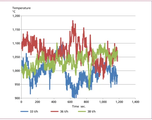
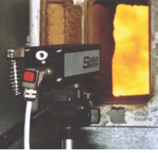
Figure 4 shows the temperatures measured by means of an IR-pyrometer (Figure 7) at a Waste-to-Energy plant for different loads at the same measurement point. The measurement point is located at the side wall of the boiler. The red line was recorded
Wolfgang Schüttenhelm, Philip Reynolds
226
Waste Incineration
at 100 percent load, the green one at 95 percent load and the blue one at 85 percent load. Obviously, the temperatures of flue gas does not behave equivalent to the loads of the steam production as it would have been expected in theory.
Figure 4: Flue gas temperatures measured in the first pass of a Waste-to-Energy plant at different loads – steam production rates
Therefore, a fast temperature measuring system is required to detect the right injecting zone. A high performance SNCR plant must have the ability to follow the changes of temperature. In case of larger cross sections even sectional deviations of temperature have to be considered by the SNCR control system in order to meet the necessary temperature operation range (Figure 3).
1.6. Influence of residence time
The temperature range shown in Figure 3 is adequate for Waste-to-Energy plants.
Usually, the residence time between injection of reduction agent and the lower SNCR temperature limit is sufficient for the reaction at larger Waste-to-Energy plants. How- ever, Waste-to-Energy plants with only one grate track and a small cross section of the first boiler path tend to higher flue gas velocities as well as high flue gas temperatures especially in case of capacity upgrades or the use of fuel with higher heating value.
Therefore, a SNCR being operated at the end of the first pass of the boiler is risking to have not enough residence time until the reactants reach the first superheaters bundles or swirls in the second pass forming cold zones. Thus, more NH3-slip will be caused
900 950 1,000 1,050 1,100 1,150 1,200
0 200 400 600 800 1,000 1,200 1,400
Temperature
°C
Time sec.
33 t/h 36 t/h 38 t/h
Dorfstraße 51 D-16816 Nietwerder-Neuruppin Tel. +49.3391-45.45-0 • Fax +49.3391-45.45-10 E-Mail: tkverlag@vivis.de
TK Verlag Karl Thomé-Kozmiensky
We dedicate ourselves to current process and plant engineering as well as political, legal and economic issues, as far as the relate to waste and recycling industries, energy and raw materials industries or immission control. Our mission is to enable communication between politics, administration, industry, science and technology.
We organize conferences and congresses and publish reference books on the prevailing issues of our target group.
Continuously, we are looking for interesting speakers, current topics and exciting projects to develop our offer. We are happy to be inspired by new ideas and discuss their feasibility.
Since more than thirty years the TK Verlag Karl Thomé-Kozmiensky publishes reference books about various themes of technical environment protection:
Our conferences at a glance:
• Berliner Abfallwirtschafts- und Energiekonferenz
• Berliner Recycling- und Rohstoffkonferenz
• Berliner Konferenz
Mineralische Nebenprodukte und Abfälle
• IRRC – Waste-to-Energy
• Berliner Immissionsschutzkonferenz
• thermal waste treatment and energetic recovery,
• mechanical-biological treatment and solid recovered fuels,
• biological waste treatment,
• recycling and raw materials,
• packaging, …
Overall, we have published around two thousand technical contributions, which represent as a whole the technical, economic, legal and political development of the last decades. More recently, we started to provide these contribu- tions for free download on our homepage.
www.
.de
Band 1 aus
Thomé-Kozmiensky + Goldmann Recycling und Rohstoffe Band 7
Thomé-Kozmiensky und Beckmann Energie aus Abfall 11 Thomé-Kozmiensky und Beckmann Energie aus Abfall 11
Thomé-Kozmiensky + Goldmann Recycling und Rohstoffe Band 5 Karl J. Thomé-Kozmiensky und Andrea Versteyl • Planung und Umweltrecht 6Karl J. Thomé-Kozmiensky und Andrea Versteyl • Planung und UmweltVersteyl • Planung und UmweltVrecht 6
IMMISSIONSSCHUTZ 2
Thomé-Kozmiensky Dombert, V ersteyl, Rotar d, Appel
4K. J. Thomé-Kozmiensky & S. Thiel WASTE MANAGEMENT 4
K. J. Thomé-Kozmiensky & S. Thiel WASTE MANAGEMENT
Karl J. Thomé-Kozmiensky Strategie Planung Umweltr echt 8
Dorfstraße 51
D-16816 Nietwerder-Neuruppin
Tel. +49.3391-45.45-0 • Fax +49.3391-45.45-10 E-Mail: tkverlag@vivis.de
Order now on www. .de
or
Dorfstraße 51
D-16816 Nietwerder-Neuruppin
Phone: +49.3391-45.45-0 • Fax +49.3391-45.45-10
E-Mail: tkverlag@vivis.de TK Verlag Karl Thomé-Kozmiensky Gewebefilter
H2O SPT
Ca(OH)2
+ HOK Kessel
Saugzug NH4OH
(SNCR)
Reststoff
Wäscher H2O
NaOH
NH3
NH4OH r
Dampf
H2O
Kondensator
Abwasser
Dagavo
Kalkmilch H2O
Rezirkulat Abwasser
Emissions-related energy indicators
for flue gas treatment systems in waste incineration
Author: Rudi Karpf ISBN: 978-3-944310-14-5
Publisher: TK Verlag Karl Thomé-Kozmiensky Released: 2014
Hardcover: 144 pages
numerous coloured images Price: 30,00 EUR
The aim of this study is to demonstrate such discrepancies or dependencies between attainable emission reductions and the emissions-generating energy input necessarily incurred by flue gas treatment technologies in attaining those reductions.
The study initially focuses on current investigations and assessments related to this issue, as well as on the legal emission requirements. Due to the wide range of components involved in flue gas treatment systems and their consequent numerous combination possibilities, six different system Variants are presented and compared. It is notable in the context of the present study that both single and two-stage or multi-stage systems are considered in the set of Variants, which differ not only in their structure and additive use but also in their separation capacity. These six basic Variants reflect the systems frequently employed in practice and represent non-congruent procedural steps with their respective target emission levels.
Based on the fact that each of these Variants is already in operation in thermal waste incineration plants, the assessment draws on many years of existing operative experience.
The individual energy demands for the Variants described are determined on the basis of mass, material and energy balances.
Evaluation criteria for energy demand at the different emission reduction ratios are educed from the formulation of emissions-related energy indicators. This establishes a set of tools with which to assess emissions-generating energy demand in the context of emission reduction ratios.
Rudi Karpf
Emissions-related energy indicators
for flue gas treatment systems in waste incineration
Emissions-related energy indicators
229 SNCR for Low NOx Emissions
Waste Incineration
subject to fast cooling below the SNCR reaction conditions. The residence time can shrink to less than 0.2 sec and limit the performance of the process. Of course, the effort to modify boiler dimensions increasing the residence time will not be justifiable in most cases. As a matter of fact, SNCR performance is limited for such boilers. Con- sequently, it is most important to apply all other methods described herein increasing SNCR performance to achieve the optimum results.
1.7. Choice of reduction agent and its distribution
Next to the injection of reduction agent into the correct temperature zone the adequate distribution of reduction agent over the cross section of the boiler is indispensable.
ERC provides suitable lance and nozzle systems achieving the best possible distribution and penetration into the boiler pass. Furthermore, urea is more suitable for difficult operational conditions of an SNCR as it takes a longer time to decompose and provide the required ammonia for the reaction. Therefore, urea is the preferred reduction agent for applications with larger combustion zones and those ones with higher temperatures.
1.8. Change of steam production
As described it is possible and common practice to increase the flexibility of the SNCR plant by installing several injection levels, a fast temperature measurement system and a fast emission measurement to cover flue gas variations. However, in order to achieve very low NOx emissions and handle difficult SNCR operational conditions the combustion process has to be optimized as well. It is necessary to homogenize the steam production by optimization of the combustion conditions. The variation of steam production is a strong indicator of the quality of the combustion conditions. [3]
2. Description of the Waste-to-Energy plant and basic design of the SNCR
The Waste-to-Energy plant of this reference case study is a modern 40 t/h steam three pass boiler. It is located in Sweden. Household waste is the main fuel and burns on a forward moving reciprocating grate. The plant produces electrical power and heat for district heating. The base NOx-content for design is 350 mg/Nm3 without any treat- ments. The limits of emission are 100 mg/Nm3 for NOx and 10 mg/Nm3 for NH3, both on a dry basis and referred to 11 Vol.% O2.
The SNCR plant as well as the grate and the boiler were designed in parallel according to the information received at that time. Therefore, operational data had not been available during the design phase.
The basic design of the SNCR plant includes three levels of injection. Due to the small dimensions of the boiler it was not intended to control the flow of the reduction agent through each lance. The active injection levels is selected depending on temperature measurements in the first boiler path.
Wolfgang Schüttenhelm, Philip Reynolds
230
Waste Incineration
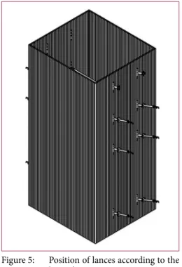
Figure 5 shows the position of the lances. The lowest level is foreseen for low load cases and starting the boiler after a revision. The highest level is a spare level which shall be used in case the temperature of flue gas would be too high at the end of boiler operation time. The upper levels equipped with lances would be the main operating levels for normal operation.
Figure 5: Position of lances according to the basic design
Ammonia water (25 percent) is used as reduction agent.
The design of the SNCR was adapted to the data of the boiler and the results of a CFD analysis comprising calculated temperature profiles.
As the control loop being based on a standard NOx rolling average controller was planned due to the fact that the emission measurement system is placed downstream of the complete flue gas treat- ment system consisting of reactors, filters and scrubbers. The flue gas needs about 3 minutes from the SNCR reaction zone to the emission measurement system. IR- pyrometers are installed in between the two upper levels providing temperature signals for SNCR control.
The mixing and dosing module is shown in Figure 6.
3. First operation experience
After finishing the installation of the boiler and the SNCR during the test phase it be- came obvious that the expected performance of the combination of boiler and SNCR could not be achieved under all operating conditions. It was possible to meet either the NOx value or the NH3 slip value within the limits by controlling the amount of reduction agent. The results of the denitrification were just a few mg/Nm3 worse. The NOx content was a little bit too high or the NH3 value.
This problem occurs at low and high load. Only between this extreme loads it was possible to stabilise the NOx control system and to achieve both emission values for some time. The reasons were unknown and had to be explored. ERC together with the boiler manufacturer started extensive investigations to identify the respective reasons and to develop an optimisation concept.
Additionally, it was monitored that the temperature profile inside the boiler quickly changed after first commissioning due to boiler fouling. Furthermore, the moisture of the waste was completely different depending on the season. Thus, the temperature profile changed, too.
231 SNCR for Low NOx Emissions
Waste Incineration
4. Investigation 4.1. Temperature measurement
A good outline of the conditions and in particular the dynamics of the furnace provides a measurement of the temperature of the flue gas with a mobile pyrometer on the basis of measurement of the infrared CO2 radiation (Figure 7). This measurement was done additionally to the installed temperature measurement system.
Figure 6:
Mixing and dosing module with control cabinet
With this mobile device it was possible to detect exactly the temperature profile from bottom to top of the boiler and over path from side to side.
Figure 8 shows a result of the measurement with this IR-pyrometer. The flue gas tempe- rature indicates a fast periodic fluctuation and significant gradients. The temperature obviously is out of the operation range (see Figure 3). The variation of temperatures is caused by the boiler control and could not foreseen during the design phase of the SNCR and was far away from the results of the CFD analysis.
Figure 7: Mobile IR-Pyrometer
Wolfgang Schüttenhelm, Philip Reynolds
232
Waste Incineration
The temperature measurements also revealed that the cooling rate of the flue gas at partial load is extremely fast and therefore, the distance between the lowest level for low load to the upper levels is too large for a smooth regulation.
4.2. Injection tests
In order to check possible solutions several injection tests were executed. The uppermost level was activated to react to higher temperatures of the flue gas at full load. As described before, it was originally planned as a spare level which is located just before the turn into the second pass. Thus, it was possible to reduce the NOx emission further, how- ever, the NH3 slip increased due to injection into a lower temperature zone. Obviously, the temperature dropped very fast in the second pass which causes NH3 slip. Closer investigations identified swirls with backflow of colder gas in the areas downstream of the bend into the second pass. Temperature measurements proofed this.
4.3. Analysis of combustion data
Data from the process control system were analysed to a great extent. It was evident that some controllers of the firing-control system over-modulated, especially the O2 controller.
5. Conclusions from the first operation and testing period
The high temperatures in combination with fast temperature fluctuation prevents meeting the emission limits of 100 mg/Nm3 NOx and 10 mg/Nm3 NH3-slip at the same time. The original design of the SNCR has to be improved. The long answering time between SNCR reaction zone and emission measurement intensifies the complexity.
Operation of the upper level – former spare level – with the complete injection of Figure 8: Flue gas temperature at highest injection level at full load
1,060 1,050
0 2 4 6 8 10
1,040 1,090 1,080 1,070 1,120 Temperature
°C
Minutes 1,110
1,100
233 SNCR for Low NOx Emissions
Waste Incineration
reduction agent is not an option due to the short residence time. However, due to the high temperature at full load it is not recommendable to disregard operation of the spare level while developing an upgraded SNCR solution.
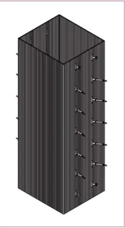
Additional levels have to be installed between the lowest level and the upper levels because of the fast cooling rate of flue gas during partial load. This permits to follow closer temperature variations which are due to changes of the fuel heating value as well as of the grate feeding process. Furthermore, part load operation will be improved by means of this measure.
6. New SNCR solution and introduced measures 6.1. Improvement of the firing control system
In cooperation with the boiler manufacturer the firing control system was improved to reduce high variation peaks of temperature. However, these adjustments were not sufficient to meet the targeted low emissions.
Figure 9: Boiler with additional levels
6.2. Redesign of the SNCR
The original design of the SNCR was based on the calculated design data of the boiler. The real operational data deviated too far from the calculated ones and, therefore, the SNCR design did not fit for all operational cases. The wide range of va- riations of the combustion parameters in combination with the wide range of fuels added to the combustion grate demands a much higher flexibility of the SNCR plant.
In order to adapt the SNCR plant to the complex situation its redesign was re- quired. Based on the results of the first operational phase and the subsequent testing period the following measures have been realised.
6.2.1. Installation of additional levels Three additional injection levels were in- stalled and equipped. The boiler layout in Figure 9 shows the additional levels which are spaced closer to each other compared to the situation before. Today, five of the seven levels can be equipped with lances
Wolfgang Schüttenhelm, Philip Reynolds
234
Waste Incineration
at the same time. It is possible to adapt the configuration to different situations such as start and end of boiler running time by changing lances manually for those special operational periods.
6.2.2. Installation of a fast NH3-measurement system at the economiser outlet To improve the possibility to react to fast changes in the combustion process as well as NOx reduction and NH3 emission an Insitu-NH3 measurement system was installed downstream the last pass of the boiler at the economiser outlet. The reaction time of the control mechanism was significantly decreased by several minutes. The NOx signal at the stack will only be used to adjust the daily average value of NOx.
6.2.3. Change of the SNCR control mechanism
In addition to the slow original control mechanism based on the NOx rolling average value this new fast simultaneous NH3 value was included in the control system of the SNCR. The NH3-slip directly effects the distribution of the controlled amount of reduction agent over up to two active levels (see also chapter 6.2.4).
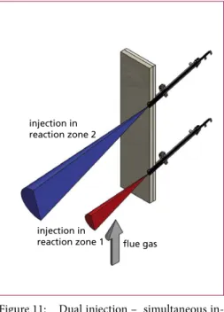
6.2.4. Injection at two selectable levels at the same time
Having recognized that the upper injection level is necessary for full load due to high temperature while the residence time is too short for a complete reaction it was decided to modify the SNCR system to simultaneously inject at two levels – ERC’s dual level injection. In a first stage, a first amount of NOx is reduced at a lower level at higher temperatures resulting in a pre-removal of NOx with almost no NH3-slip.
Figure 10:
Mixing and dosing module after redesign
235 SNCR for Low NOx Emissions
Waste Incineration
Consequently, the second injection level being operated at lower temperature requires less reduction agent to achie- ve the final NOx emission limit value without too much surplus resulting in a lower NH3-slip compared to the one level injection. In summary, the complete reduction is split into two stages which do not even need to be at the same high efficiency as a single reaction. Figure 12 shows the diagram known from Figure 2 and from Figure 3 with the two reaction zones. Although both injection levels are not operating at the temperature optimum but in combination they fit the purpose well.
Each amount of reduction agent for the two levels is controlled by an individu- al control loop which depends on the emission of NOx and NH3. ERC named this concept the reaction cloud based on
100
80 90
70 60 50 40 30 20 10 0 NOX-Reduction
%
NH3-slip mg/m3 20
16
12
8
4
0
750 850 950
Reaction Temperature °C
reaction zone 2 reaction zone 1
1,050 1,150
Figure 11: Dual injection – simultaneous in- jection to create a double reaction zone
Figure 12:
SNCR temperature window with the two reaction zones of the dual injection system
injection in reaction zone 2
injection in
reaction zone 1 flue gas
the picture of creating a cloud of reduction agent with locally different ammonia concentrations in the lower and upper part of the cloud.
Figure 10 shows the new mixing and dosing being capable to inject at two levels with different amounts and different concentration of reduction agent at the same time.
Wolfgang Schüttenhelm, Philip Reynolds
236
Waste Incineration
6.3. Acceptance Test
After redesigning and installation of the modified SNCR as well as commissioning the plant fulfilled the acceptance test for both full load as well as partial load. Those acceptance test measurements were executed by an independent certified measurement company.
7. Summary
This case study demonstrates that real operational parameter of a Waste-to-Energy plant can severely deviate from originally calculated or estimated design values. Especially, units with smaller capacities are subject to larger deviations as any inhomogeneity of the combustion will result in more difficult and complex conditions for the SNCR performance. This is due to the fact that less means are available to improve waste mixing, homogenise waste feeding or adjust combustion parameters. A structured analysis of plant operation based on long years of experience and data gathered by means of modern measurement devices were proven to be appropriate tools to identify problems and develop solutions.
Since rebuilding of the SNCR the very stringent limits of 100 mg/Nm3 NOx and 10 mg/Nm3 NH3 could safely be met even for this small capacity 40 t/h unit.
A higher flexibility of the SNCR plant and appropriate sensor technology is required to deal with larger fluctuations of combustion parameters. The better the reasons of such fluctuations are described during the design phase the SNCR can be designed more precisely. In order to achieve the above very low emission values ERC’s dual injection system offers a new solution. The created reaction cloud enables an excellent NOx reduction with low NH3-slip even for smaller boilers. This flexible system adapts fast to changes of flue gas parameters due to the separately controlled amounts of reduction agent and distribution water for each level.
Stabilisation of the combustion process is an appropriate means to improve the deni- trification, too.
8. Literature
[1] Hukriede, J.; Reynolds, P.; Pachaly, R: Neue 17. BImSchV – Auswirkungen auf bestehende Ab- fallverbrennungsanlagen mit SNCR-Technik sowie Lösungskonzepte. In: Thomé-Kozmiensky, K. J.; Beckmann, M. (eds.): Energie aus Abfall, Band 11. Neuruppin: TK Verlag Karl Thomé- Kozmiensky, 2014
[2] Reynolds, T.: Können SNCR-Verfahren die zukünftigen Grenzwerte einhalten? In: Thomé- Kozmiensky, K. J.; Beckmann, M. (eds.): Energie aus Abfall, Band 9. Neuruppin: TK Verlag Karl Thomé-Kozmiensky, 2012
[3] Schüttenhelm, W.; Huber, K.; Teuber, Z.: SNCR Technology for Large Combustion Plants – Operational Experiences with a Commercial Installation in a 225 MWel Coal-Fired Boiler. VGB PowerTech. December, 2013
[4] Schüttenhelm, W.; Reynolds, P.; Hukriede, J.: Einhaltung verschärfter NOx- und NH3-Grenz- werte bei bestehenden Anlagen – Vorgehen und Lösungsansätze anhand von Praxisbeispielen.
In: Thomé-Kozmiensky, K. J.; Beckmann, M. (eds.): Energie aus Abfall, Band 12. Neuruppin:
TK Verlag Karl Thomé-Kozmiensky, 2015
Dorfstraße 51 D-16816 Nietwerder-Neuruppin Tel. +49.3391-45.45-0 • Fax +49.3391-45.45-10 E-Mail: tkverlag@vivis.de
Bestellungen unter www. .de
oder
TK Verlag Karl Thomé-Kozmiensky
Reinigung von Abgasen
Dieses umfassende Lehr- und Praxishandbuch stellt die Abgasreinigung nach der thermischen Abfallbehandlung ausührlich dar, hebt deren Besonderheiten hervor und erläutert die Unterschiede zu Abgasreinigungssystemen nach der thermischen Behandlung anderer Brennstoffe.
Behandelt werden die Herkunft und Wirkung von verbrennungscharakteristischen Luftschadstoffen, deren Entstehungsme- chanismen im Verbrennungsprozess, Primär- und Sekundärmaßnahmen zu ihrer Reduzierung, Verfahren zur Emissionsmes- sung sowie Entsorgungsverfahren für Rückstände aus der Abgasreinigung. Insbesondere die Vor- und Nachteile von Verfahrensschritten und deren sinnvolle Kombination bei unterschiedlichen Randbedingungen werden herausgestellt.
Zudem enthält das Buch Informationen und Analysen zur Emissionssituation, zu Betriebsmittelverbräuchen und Rückstands- mengen sowie zur Kostenstruktur von thermischen Abfallbehandlungsanlagen in Abhängigkeit des eingesetzten Abgasreini- gungssystems. Darüber hinaus werden Informationen zu aktuellen rechtlichen, wissenschaftlichen und technologischen Entwicklungen und deren Einfluss auf die Abgasreinigung gegeben. Eine Auswertung des Status quo der Abgasreinigung nach der Abfallverbrennung in Deutschland, Ausführungsbeispiele zu den möglichen Aggregatekombinationen und typische Betriebswerte aus der Anlagenpraxis runden den Inhalt ab.
Damit ist das Werk zugleich ein Leitfaden zur Planung des für einen Standort und eine Abscheidungsaufgabe schlüssigen Gesamtkonzepts zur Abgasreinigung. Das Buch richtet sich an Studierende an Fach- und Hochschulen, an Entscheidungsträ- ger, Planer und die betriebliche Praxis, beispielsweise wenn der Neubau eines Systems oder die Implementierung von Optimierungsmaßnahmen durchgeführt werden soll.
Reinigung von Abgasen
– unter besonderer Berücksichtigung der thermischen Abfallbehandlung –
Autor: Margit Löschau Erschienen: 2014
ISBN: 978-3-944310-13-8 Hardcover: 476
Preis: 50,00 EUR
Transformationen unterhalb der Wolken
Emissionen Transmissionen Depositionen / Immissionen Ferntransport
Transformationen innerhalb der Wolken Ausregnung Nebelwirkung
Trockene Deposition
Nährstoff-f- auswaschung auswaschung
Oberflächen- abfluss abfluss
Vorwort
4
Bibliografische Information der Deutschen Nationalbibliothek Die Deutsche Nationalbibliothek verzeichnet diese Publikation in der Deutschen Nationalbibliografie; detaillierte bibliografische Daten sind im Internet über http://dnb.dnb.de abrufbar
Thomé-Kozmiensky, K. J.; Thiel, S. (Eds.): Waste Management, Volume 5 – Waste-to-Energy –
ISBN 978-3-944310-22-0 TK Verlag Karl Thomé-Kozmiensky
Copyright: Professor Dr.-Ing. habil. Dr. h. c. Karl J. Thomé-Kozmiensky All rights reserved
Publisher: TK Verlag Karl Thomé-Kozmiensky • Neuruppin 2015
Editorial office: Professor Dr.-Ing. habil. Dr. h. c. Karl J. Thomé-Kozmiensky, Dr.-Ing. Stephanie Thiel, M. Sc. Elisabeth Thomé-Kozmiensky.
Layout: Sandra Peters, Ginette Teske, Janin Burbott-Seidel, Claudia Naumann-Deppe Printing: Universal Medien GmbH, Munich
This work is protected by copyright. The rights founded by this, particularly those of translation, reprinting, lecturing, extraction of illustrations and tables, broadcasting, micro- filming or reproduction by other means and storing in a retrieval system, remain reserved, even for exploitation only of excerpts. Reproduction of this work or of part of this work, also in individual cases, is only permissible within the limits of the legal provisions of the copyright law of the Federal Republic of Germany from 9 September 1965 in the currently valid revision. There is a fundamental duty to pay for this. Infringements are subject to the penal provisions of the copyright law.
The repeating of commonly used names, trade names, goods descriptions etc. in this work does not permit, even without specific mention, the assumption that such names are to be considered free under the terms of the law concerning goods descriptions and trade mark protection and can thus be used by anyone.
Should reference be made in this work, directly or indirectly, to laws, regulations or guide- lines, e.g. DIN, VDI, VDE, VGB, or these are quoted from, then the publisher cannot ac- cept any guarantee for correctness, completeness or currency. It is recommended to refer to the complete regulations or guidelines in their currently valid versions if required for ones own work.