Waste Incineration
Simple and Effective – the Conditioned Dry Sorption Process for Flue Gas Treatment Downstream Waste Incinerators
Rüdiger Margraf
1. Conditioned dry sorption process ...254
1.1. General description ...254
1.2. Application example ...256
2. Utilisation of CaO instead of Ca(OH)2 for the reduction of operating costs ...259
3. Advantages of conditioned dry sorption compared to the spray sorption ...261
3.1. Comparison ...261
3.2. Application example ...262
4. Combination of conditioned dry sorption with a wet fine cleaning stage ...264
4.1. General design ...264
4.2. Acid scrubbing stage ...265
4.3. Basic scrubbing stage ...266
5. Assessment ...267
6. References ...267 The conditioned dry sorption with utilisation of Ca-based additive powder qualities became increasingly important in Europe in the course of the past years regarding the application waste incineration plants. Starting from the prohibition of disposal in the year 2005 until today, the vast majority of new plants for waste and RDF combustion in Germany has been provided with a conditioned dry sorption system. This trend continues with regard to the new planning of WtE-plants in Europe and other parts of the world.
As a result of continuous further developments, this procedure gave proof of its reli- ability, performance and not least of its economic efficiency in comparison to other technologies available on the market. Particularly in the course of the last years, tech- nical optimisation steps had been necessary to be able to keep up with the increasing
Waste Incineration
requirements, resulting from higher crude gas loads and the demand for lower emission values. A further aspect as urge for the optimisation of process technologies is the cons- tant pressure to increase the competitiveness of plants by means of low operating costs.
In the following the conditioned dry sorption process is introduced including possible steps for optimisation and an assessment on the basis of practical examples. It may be remarked in addition that the main focus of this lecture is on the sorption of the acid crude gas components HCl and SOx. The qualification of process for the simultaneous separation of further pollutants existing in the gas such as e.g. dioxins/furans as well as mercury and other heavy metal compounds or also the excellent separation of filter dust of type PM 10 and PM 2.5 will not be discussed in this lecture.
1. Conditioned dry sorption process 1.1. General description
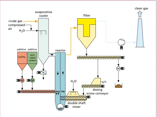
A schematic view of the conditioned dry sorption process is given in Figure 1 using the example of Luehr Filter – Conditioning Rotor – Recycle Process with particle condi- tioning. It mainly comprises the component parts evaporative cooler, additive powder injection, conditioning rotor reactor, fabric filter as well as particle re-circulation with integrated particle conditioning. Further possible design types are described in [2].
dosing screw conveyor double shaft
mixer
clean gas
reactor evaporative
cooler
Ca(OH)2
Acti- vated carbon additive additive compressed air crude gas
filter
H2O H2O
Figure 1: Schematic view of conditioned dry sorption process with particle and gas conditioning
Waste Incineration
The evaporative cooler (gas conditioning) serves for the optimum temperature ad- justment for the reaction between the additive particles and the acid gas molecule, combined with an increase in the absolute and relative humidity for the optimisation of the separation efficiency with at the same time good additive powder utilisation.
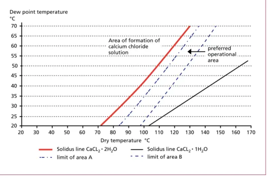
Whereas in case of use of Ca-based additive powders, the separation of SO3 and HF takes place with a high reaction velocity in the complete temperature range, the dry temperature as well as the absolute and relative humidity in the gas have a considerable influence on the HCl and SO2 separation. Decreasing temperature and increasing hu- midity will improve the efficiency. Depending on the parameters of an application, the min. admissible operating temperature has to be chosen in that way, that deposits and blockages, especially due to the hygroscopic features of CaCl2 particles, will be avoided within the plant. The preferred operating range for the dry temperature depending on the dew point temperature is shown in Figure 2.
30 40
Dry temperature °C 70
65 60 55
45
35
25
Dew point temperature
°C
20 20 50
40
30
50 60 70 80 90 100 110 120 130 140 150 160 170
Solidus line CaCL2 • 2H2O Solidus line CaCL2 • 1H2O limit of area A limit of area B
Area of formation of calcium chloride
solution preferred
operational area
Figure 2: Phase diagram CaCl2• n H2O
Source: Karp, Dr. Mosch
The separation stage, composed of conditioning rotor reactor with additive powder injection, fabric filter and multiple particle re-circulation incl. particle conditioning, serves for the following:
• Creation of good reaction conditions of up to n • 100 g/m³ due to the particle re- circulation.
Waste Incineration
Especially when realising high, up to 50-fold, additive powder recycle rates, the particle recirculation demonstrably leads to a considerable improvement of the separation capacity regarding acid crude gas components and/or to a reduction in the additive powder injection rate [6].
– Increase in residence time of additive powder particles in the system.
– Higher additive powder density near the reactor upstream filter (the reaction time within reactor amounts to up to > 2 sec.).
– A frequent, spatial new orientation of the re-circulated additive powder particles with rebuild of filter cake on the filter fabric.
It should be noted that the multiple particle recirculation also has an advantageous effect on the reliable observance of limit values for dioxins/furans and mercury as well as mercury compounds with an at the same time low injection quantity of AC.
The large additive powder potential within the system also helps to observe reliably the limit values during Hg peaks.
• Improvement particularly with regard to the SO2 separation, due to the wetting of the re-circulated particulate
As described before and as a result of the increase in the absolute and relative humidity of the flue gas, the gas conditioning has a positive effect on the sorption output. However, a good additive powder efficiency, especially for the separation of SO2, can only be achieved if the water steam partial pressure lose to the additive particles lies at least for a short time in the range of the saturation steam pressure.
This will be achieved by wetting of the recycled particulate prior to reinjection into the reactor. Up to the evaporation of the water injected into the humidifying mixer, the wetting causes an increase in the water steam content at the surface of additive powder particles, thus improving the reactivity regarding the acid crude gas components.
The operating results of many realised plants confirm that when using this technology, stoichiometric factors clearly below 2-fold can be achieved [4, 8].
1.2. Application example
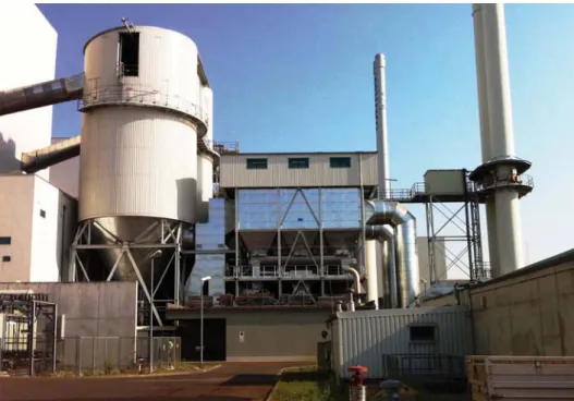
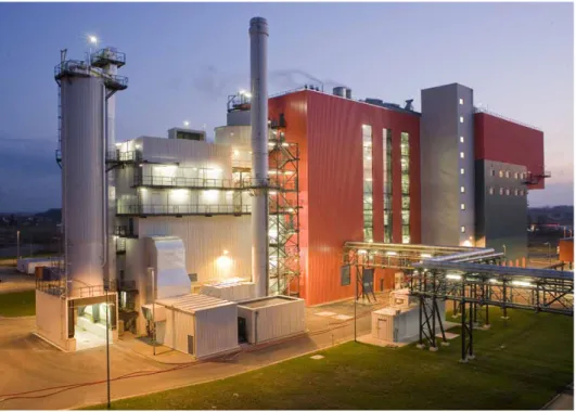
Representing many realised plants with conditioned dry sorption process, Figure 3 shows the gas cleaning system of line no. 2 of the WtE plant in the city of Ludwigsha- fen/Germany. Furthermore, in addition to the photo of plant, a table shows the crude gas values downstream boiler. The emission limit values to be observed correspond, for most of the gas substances, to the requirements of the EU directive. Furthermore, regarding SO2, a limit value of 25 mg/Nm3 and for Hg a limit value of 15 µg/Nm³ has to be observed.
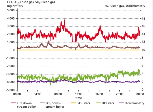
Figure 4 shows the trend curves of crude gas and clean gas values for HCl and SO2 over a period of 24 hours as well as the stoichiometric factor for the Ca(OH)2 injection.
Waste Incineration
In case of an average HCl crude gas value of approx. 2,000 mg/Nm³ (1,250 ppm), clean gas values of approx. 5 mg/Nm³ (3 ppm) will be achieved. The SO2 crude gas values of in average approx. 450 mg/Nm³ (160 ppm) will be separated to approx. 100 percent.
The stoichiometry totals to a factor of < 1:8.
Figure 3: WtE plant Ludwigshafen/Germany
Volume flow:
90,000 Nm3/h humid
Gas take-over Emission limit values
DAV HAV DAV HAV
Overall dust mg/Nm3dry 1,600 5,000 10 20
HCI mg/Nm3dry 1,000 2,000 10 60
HF mg/Nm3dry 15 30 1 4
SO2 mg/Nm3dry 400 600 25 150
Hg mg/Nm3dry 0.3 0.3 0.015 0.03
Cd + TI mg/Nm3dry 1.0 3.0 0.05*
∑ (Sb, As, Pb, Cr,
Mn, Ni, V, Sn) mg/Nm3dry 20 50 0.5*
Dioxin/Furan ngTE/Nm3dry 3.0 5.0 0.1*
* Average value over sample taking period
Figure 4: Trend curves crude gas/clean gas values and stoichiometry
08:00 16:00 20:00
2,000 1,000 0 -1,000 -2,000 -3,000 -4,000
HCI, SO2-Crude gas, SO2-Clean gas mg/Nm3dry
00:00 04:00 12:00
-5,000 5,000 4,000 3,000
HCI-Clean gas, Stoichiometry
12 10 8 6 4 2 0 18 16 14
00:00 time
HCI down-
stream boiler SO2 down-
stream boiler SO2 stack HCI stack Stoichiometry
Waste Incineration
Table 1 shows the results of a dioxin measurement. The specific injection quantity of AC totals to approx. 70 mg/Nm3. Even the requested emission limit values for Hg will reliably be kept in continuous operation with this injection quantity.
Summary of measuring results
The table below shows a summary of measuring results. The concentrations are referred to the standard conditions (1.013 hPa, 273 K) and dry exhaust gas.
Table 1b: Results of dioxin/furan measurement WtE plant Lud- wigshafen – referred to stadard conditions, dry exhaust gas and addition to an oxygen content of 11 vol.-%
Table 1a: Results of dioxin/
furan measurement WtE plant Ludwigshafen – referred to the standard conditions (1.013 hPa, 273 K) and dry exhaust gas
Measurement 1 2 3
Dust mg/m3 1.4 < 1.0 < 1.3
PCDD/PCDF I-Teq. accord. ng/m3 < 0.001 <0.001 <0.001 to annex 17.BImSchV
In the following table the concentrations are referred to stadard conditions (1.013 hPa, 273 K), dry exhaust gas and addition to an oxygen content of 11 vol.-percent.
Measurement 1 2 3
Dust mg/m3 1.1 < 0.9 < 1.1
PCDD/PCDF I-Teq. accord. ng/m3 < 0.001 <0.001 <0.001 to annex 17.BImSchV
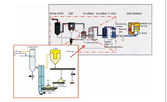
The conditioned dry gas cleaning system installed in 2004, replaced a definitely more complex, wet system, consisting of spray dryer, ESP, multi-stage scrubber and aerosol separator (Figure 5).
Dosing screw conveyor Double shaft
mixer
Clean gas
Reactor Evaporative
cooler Compressed air Crude gas
Filter
NaOH TMT 15 Activated carbon Lime slurry
Remainder
Spray dryer ESP Scrubber Scrubber 3 EDV SCR-DENOX
Ammonia water
Natural gas NaOH
H2O
H2O
DENOX-Cat Oxi-Cat
Stack
Figure 5: Upgrading of WtE plant Ludwigshafen from wet to conditioned dry
Source: TWL
Waste Incineration
Up to the year 2008, another wet flue gas treatment system had been operated in parallel at the waste incinerator in Ludwigshafen until its upgrading, thus allowing a direct comparison between both installed systems.
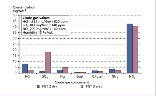
Figure 6 shows the average values for selected gas substances of the year 2005.
The comparison shows that the conditioned dry sorption system is equal to the more complex wet system. The only difference is the reference variable for the separation of the acid crude gas components, i. e. SO2 for the scrubber and HCl for the conditioned dry sorption [9].
Figure 6: Comparison of gas cleaning systems wet and conditioned dry (2005)
2. Utilisation of CaO instead of Ca(OH)
2for the reduction of operating costs
In case of the conditioned dry sorption, the Ca-based additive powder is injected into the reactor dry in form of Ca(OH)2. Compared to the use of CaO as e.g. for the spray sorption, this presents a disadvantage due to the higher purchase costs for Ca(OH)2. In order to compensate this cost disadvantage, plants with a higher additive powder consumption are often provided in addition with a dry hydrator for CaO [5]. In this case, the additive powder is supplied in form of CaO. It is converted to Ca(OH)2 by means of H2O injection in a dry hydrator and is stored in an intermediate silo for the injection into the reactor and/or also upstream evaporative cooler as dry additive powder. The intermediate silo is adequately dimensioned to allow a direct filling of silo with Ca(OH)2 in case of maintenance and repair works near the dry hydrator. A corresponding scheme is shown in Figure 7.
Concentration mg/Nm3
HCI SO2 Hg Dust C total NH3 NO2
Crude gas compenent
FGT 2 dry FGT 3 wet
0 5 10 15 20 25 30 35 40 45
50 Crude gas values:
HCI 1,335 mg/Nm3 / 820 ppm SO2 303 mg/Nm3 / 140 ppm NOx 290 mg/Nm3 / 140 ppm Humidity 13 % Vol.
Waste Incineration
Figure 7:
Rough scheme dry hydration CaO
Dosing balance H2O
Dry hydrator CaO
CaO Silo
Ca(OH)2
Ca(OH)2 Silo
towards lime dosing TIC
Several plants in Germany have been provided with this technology.
Figure 8 shows a plant, realised with a dry hydrator for a Ca(OH)2 production capacity of approximately 3 t/h.
Figure 8: RDF incineration plant EEW Premnitz / Germany
As alternative there is the possibility to install the dry hydrator close to the additive powder injection point near the reactor. The produced Ca(OH)2 can now be injected directly into the reactor without temporary storage in a silo.
Figure 9 shows such a dry hydrator as well as the corresponding WtE plant.
Waste Incineration Figure 9: Compact dry hydrator for CaO
3. Advantages of conditioned dry sorption compared to the spray sorption 3.1. Comparison
Comparative examinations regarding the additive powder utilisation have been realised at a plant in Germany, provided with both a spray sorption and a conditioned dry sorption [1]. The result was a definitely lower additive powder consumption in case of consistent operation of dry sorption compared to the spray sorption. The relevant reasons for this are:
• Formation of CaCO3 during the aqueous phase
Compared to the acid crude gases HCl, HF and SO2, the slightly acid carbon dioxide has a minor affinity to hydrated lime. However, the concentration of CO2 within the gas is definitely higher. A CO2 concentration of approximately 10 Vol.-percent, cor- responding to 100,000 ppm, is faced with a HCl concentration of e.g. 1,600 mg/m³, corresponding to 1,000 ppm. During the wet phase a considerable amount of CaCO3 will be formed which – after drying of lime slurry drops – will be only very limited available for the reaction.
A disadvantage of incinerators for waste and alternative fuels is, that due to the hygroscopic features of CaCl2 , a temperature reduction to values definitely below 140 °C and by this a possible reactivation of the CaCO3 during the wet phase will not be possible. In case of a corresponding water injection, the downstream installed conditioned dry sorption may lead to a partial reactivation of the CaCO3.
• Formation of agglomerates
The microscopic photos in Figure 10 show fresh hydrated lime particles compared to calcareous particles extracted downstream spray absorber. The freshly slaked hydrated lime has a clearly visible, high outer surface. However, after drying within spray absorber, this will be reduced due to the formation of drop shaped agglome- rates. The exchange surface necessary for the chemical reaction will be reduced.
Waste Incineration
• Influence of particle re-circulation
As described in section 2 of this lecture, the multiple particle re-circulation of the conditioned dry sorption creates a higher particle density within reactor and incre- ases the residence time of additive powder. In addition, the separation conditions within filter will be improved.
Figure 10: Surface structure of Ca(OH)2, upstream and downstream spray absorber [1]
Due to the multiple particle re-circulation, the conditioned dry sorption offers advanta- ges regarding the separation of dioxins/furans and mercury. Last but not least, even in case of crude gas peaks, the limit values will reliably be observed with low AC injection.
3.2. Application example
Recently the existing spray sorption of a waste incinerator in Germany has been mo- dified to the conditioned dry sorption process. The reasons for the modification are the following:
• Reliable observance of emission limit value for SO2 and HCl even in case of arising crude gas peaks.
• Clear reduction in additive powder consumption rate for the optimisation of ope- rating costs.
Figure 11 shows the gas cleaning system after modification. The spray absorber was kept as unit but now mainly serves as evaporative cooler for the adjustment of the optimum reaction temperature. A small quantity of additive powder is still injected as suspension for the reduction of acid dew point and a graded sorption. Depending on the crude gas input values, the main quantity of additive powder is injected into the reactor upstream filter in the form of Ca(OH)2. Ca(OH)2 is produced on site from CaO by means of a dry hydrator.
Fresh hydrated lime Calcareous particles from a spray sorption at waste incinerator with lime slurry
Waste Incineration
Figure 12: Trend curves MHKW Rothensee
Figure: 11: Gas cleaning system of MHKW Rothensee
time 6:00 8:00
2.000
1.500
1.000
500 crude gas mg/m3 dry
0:00 2:00 4:00 0
2.500
40
30
20
10
0 50 clean gas mg/m3 dry
HCI crude gas SO2 crude gas HCI clean gas SO2 clean gas 10:00 12:00 14:00 16:00 18:00 20:00 22:00 0:00
Waste Incineration
Figure 12 shows the separation efficiency of process by means of continuously measu- red crude gas and clean gas concentrations for HCl and SO2 over a period of time of 24 hours. It is clearly visible that not least as a result of the multiple particle re-circulation and the wetting of the re-circulated particulate the limit values can reliably be kept in automatic operation even in case of HCl and SO2 peaks.
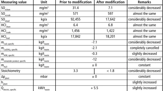
Table 2 shows a summary of the positive results of modification. The high particle re-circulation combined with the particle wetting results in a significant saving of ad- ditive powder costs. The stoichiometry could be reduced from 3.3-fold to < 1.8-fold.
Furthermore, the SO2 separation could be improved as a result of the particle condi- tioning. Based on approximately the same crude gas values, the clean gas value could be reduced from > 30 mg/Nm³ to approximately 7 mg/Nm³ [3].
Table 2: Results of modification
Measuring value Unit Prior to modification After modification Remarks
SOxclean mg/m3 31.4 7.1 considerably decreased
SOxcrude mg/m3 571 597 almost the same
SOxload kg/a 92,455 17,642 considerably decreased
HCIclean mg/m3 6.4 6.8 almost the same
HCIcrude mg/m3 1,456 1,422 almost the same
HCIload kg/a 17,842 18,201 almost the same
mCaO, specific kg/twaste -7.1 considerably decreased
mCa(OH)2, specific kg/twaste -2.1 completely cancelled
mHOK, specific kg/twaste -0.3 slightly decreased
mremainder product, specific kg/twaste -12 considerably decreased
mH2O kg/twaste ± 0 constant
Stoichiometry 3.3 < 1.8 considerably decreased
∆pplant mbar ± 0 constant
hplant slightly increased
Qelectric, specific kW/twaste + 5.5 slightly increased
4. Combination of conditioned dry sorption with a wet fine cleaning stage 4.1. General design
At this process concept, the conditioned dry sorption is operated in such way, that the exhaust gas escaping from this stage most closely complies with the requirements of e.g. 17 BImSchV. or EU Directive 2000/76/EC. Depending of the application in ques- tion, the remaining objectives of the downstream installed wet fine cleaning stage are
• the separation of NH3,
• the further reduction of emission values, e.g. for acid crude gas components,
• the heat recovery.s
Waste Incineration
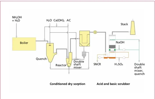
Particularly in case of high requirements on the NOx reduction, this process variant can offer advantages. The reduction of NOx will furthermore be realised by means of an SNCR-process, however, with acceptance of a higher NH3 slippage flow. The NH3 is separated in the acid scrubbing stage [7]. Figure 13 shows a schematic view of process combination. The process is working free of waste water.
Conditioned dry sorption Acid and basic scrubber Boiler
Quench
Reactor
Double shaft
mixer SNCR 2SO4
Stack
NaOH
Double shaft mixer, quench H2O Ca(OH)2 AC
NH4OH + H2O
H
Figure 13: Combination of conditioned dry sorption – acid and basic scrubbing
4.2. Acid scrubbing stage
The acid scrubbing stage serves for the separation of NH3, HCl and partly of SO2. To allow this, the gas is cooled down to the saturation temperature by injecting scrubbing water.
In order to ensure a sufficient NH3 separation, the ph-value in the scrubbing water of the acid stage has to be sufficiently low. Only in case of a definitely acid operating mode, an efficient separation of NH3 can be achieved. In this respect, the ph-value will be measured and possibly adjusted by injection of H2SO4. An example for this is a realised plant that allows a reliable NH3 reduction in continuous operation of approx.
15 mg/Nm³ dry to < 5 mg/Nm³ dry at a ph-value of < 5.6 [7]. Depending on the NH3- and HCl concentration, a sufficiently low ph-value will temporarily be reached in the water, even without injecting other chemicals.
A high-capacity droplet separator is installed downstream of acid scrubbing stage, in order to achieve a clear separation between the acid and the basic stage, thus allowing a separate reuse of waste water from both stages. In case of a necessary NH3 separation, a direct injection of purge water from the acid stage into the quench of the conditioned
Waste Incineration
dry sorption or the humidifying mixer of this stage will not be possible. Failing the discharge of NH3, this substance would be released again in case of contact with the basic additive powders and in connection with water. It is appropriate to inject this small water quantity in the boiler near the SNCR process. The NH3 in the water can be used again for the reduction of NOx. Referred to the HCl mass flow from the fuel, the inlet of HCl is very low. Negative influences on the process, e.g. due to a rise in the HCl concentration upstream crude gas cleaning, have to be excluded.
4.3. Basic scrubbing stage
The basic scrubbing stage serves for the further separation of SO2.
To allow this, a pH-value > 6 has to be adjusted by means of application-related injec- tion of NaOH. Even in this case a droplet separator is installed downstream of stage.
A small amount of waste water has continuously to be extracted. The purge volume will be kept at such a low level that this water can be used in the evaporative cooler of conditioned dry sorption or also in the humidifying mixer of this stage for the cooling of gas downstream boiler and/or for the conditioning of recycled particulate without any further treatment. Condition for this is of course that the acid crude gases are basically separated in the conditioned dry sorption stage and that the scrubber is operated as fine cleaning stage.
Several flue gas treatment plants provided with this process are successfully working downstream waste combustion plants. Figure 14 shows as an example the waste com- bustion plant in Oulu/Finland.
Figure 14: Domestic and industrial waste combustion, Oulu/Finland
Waste Incineration
5. Assessment
The present operating experiences gathered from a multitude of realised plants with conditioned dry sorption technology confirmed its potential and reliability.
• The requested emission limit values are reliably kept in continuous operation
• Crude gas peaks are reliably compensated due to the large additive powder potential within the plant
• The stoichiometric factor for the Ca(OH)2 injection for the separation of acid crude gas components normally totals to a value clearly below
• CaO can be used as additive powder with saving of costs
• The injection quantity for AC totals to a specific value of approximately 0.07 gr/scf
• The comparatively simple structure grants a high availability
To be able to use all process-related advantages of this technology, the basic variant of the conditioned dry sorption has possibly to be adjusted to the requirements of each application by means of modifications, such as graded additive powder injection or also downstream installation of a fine cleaning stage.
6. References
[1] Karpf, R.; Conrad, Y.: Sprühabsorptionsverfahren hinter Abfallverbrennungsanlagen – wie kön- nen hohe Rohgaswerte, insbesondere für SO2 beherrscht werden; 7. Tagung Trockene Abgasrei- nigung für Feuerungsanlagen und andere thermische Prozesse, Haus der Technik Essen, 2011 [2] Löschau, M.; Thomé-Kozmiensky, K. J.: Reinigung von Abgasen aus der Abfallverbrennung.
Energie aus Abfall, Band 7, 2010
[3] Lücker, G.: Optimisation of spray absorption of MHKW Rothensee – a challenge? Berliner Abfallwirtschafts- und Energiekonferenz, Optimierung der Abfallverbrennung, 2015
[4] Margraf, R.: Assessment of dry and semi-dry sorption procedures on the basis of practice-related examples from the field of incineration plants, International Recycling + Recovery Congress, Wien, 2014
[5] Margraf, R.: Conditioning Rotor-Recycle Process with particle conditioning – a simple and effective process for the gas cleaning downstream waste incinerators; NAWTEC 18, Orlando/
Florida, 2010
[6] Margraf, R.: Single and multi-stage procedures for the gas treatment downstream incineration plants; VDI-Wissensforum Betriebsmittel in der Rauchgasreinigung, Bremen, 2011
[7] Margraf, R.: TwinSorp® – a simple process for increased requirements on the emission limit values i. a. for waste and RDF incinerators, considering the energy efficiency command: 6th symposium;
Dry crude gas cleaning for solid fuel firings and thermal process technology, Haus der Technik Essen, 2010
[8] Plepla, K.-H.; Margraf, R.: First operating experiences gathered from the conditioned dry gas cleaning system at RDF HKW Stavenhagen; 3rd symposium; Dry crude gas cleaning for solid fuel firings and thermal process technology, Haus der Technik, Essen, 2007
[9] Wradatsch, R.: Entwicklung und Betriebserfahrungen mit der konditionierten Trockensorp- tion des MHKW Ludwigshafen; 3. Fachtagung Trockene Abgasreinigung für Festbrennstoff- Feuerung und thermische Prozesstechnik, Haus der Technik Essen, 2007
Dorfstraße 51
D-16816 Nietwerder-Neuruppin
Tel. +49.3391-45.45-0 • Fax +49.3391-45.45-10 E-Mail: tkverlag@vivis.de
Bestellungen unter www. .de
oder
TK Verlag Karl Thomé-Kozmiensky
Aschen • Schlacken • Stäube
– aus Abfallverbrennung und Metallurgie –
ISBN: 978-3-935317-99-3
Erschienen: September 2013 Gebundene Ausgabe: 724 Seiten
mit zahlreichen farbigen Abbildungen
Preis: 50.00 EUR
Aschen • Schlacken • Stäube
Herausgeber: Karl J. Thomé-Kozmiensky • Verlag: TK Verlag Karl Thomé-Kozmiensky
Thomé-Kozmiensky und VersteylAschen • Schlacken • StäubeThomé-Kozmiensky
Karl J. Thomé-Kozmiensky
Aschen • Schlacken • Stäube
– aus Abfallverbrennung und Metallurgie –
M M
M M
M M
M M
M M M M
M M M
M
Der Umgang mit mineralischen Abfällen soll seit einem Jahrzehnt neu geregelt werden. Das Bundesumweltministerium hat die Verordnungs- entwürfe zum Schutz des Grundwassers, zum Umgang mit Ersatzbaustoffen und zum Bodenschutz zur Mantelverordnung zusammengefasst.
Inzwischen liegt die zweite Fassung des Arbeitsentwurfs vor. Die Verordnung wurde in der zu Ende gehenden Legislaturperiode nicht verabschiedet und wird daher eines der zentralen und weiterhin kontrovers diskutierten Vorhaben der Rechtssetzung für die Abfallwirtschaft in der kommenden Legislaturperiode sein. Die Reaktionen auf die vom Bundesumweltministerium vorgelegten Arbeitsentwürfe waren bei den wirtschaftlich Betroffenen überwiegend ablehnend. Die Argumente der Wirtschaft sind nachvollziehbar, wird doch die Mantelverordnung große Massen mineralischer Abfälle in Deutschland lenken – entweder in die Verwertung oder auf Deponien.
Weil die Entsorgung mineralischer Abfälle voraussichtlich nach rund zwei Wahlperioden andauernden Diskussionen endgültig geregelt werden soll, soll dieses Buch unmittelbar nach der Bundestagswahl den aktuellen Erkenntnis- und Diskussionsstand zur Mantelverordnung für die Aschen aus der Abfallverbrennung und die Schlacken aus metallurgischen Prozessen wiedergeben.
Die Praxis des Umgangs mit mineralischen Abfällen ist in den Bundesländern unterschiedlich. Bayern gehört zu den Bundesländern, die sich offensichtlich nicht abwartend verhalten. Der Einsatz von Ersatzbaustoffen in Bayern wird ebenso wie die Sicht der Industrie vorgestellt.
Auch in den deutschsprachigen Nachbarländern werden die rechtlichen Einsatzbedingungen für mineralische Ersatzbaustoffe diskutiert. In Österreich – hier liegt der Entwurf einer Recyclingbaustoff-Verordnung vor – ist die Frage der Verwertung von Aschen und Schlacken Thema kontroverser Auseinandersetzungen. In der Schweiz ist die Schlackenentsorgung in der Technischen Verordnung für Abfälle (TVA) geregelt, die strenge Anforderungen bezüglich der Schadstoffkonzentrationen im Feststoff und im Eluat stellt, so dass dies einem Einsatzverbot für die meisten Schlacken gleichkommt. Die Verordnung wird derzeit revidiert.
In diesem Buch stehen insbesondere wirtschaftliche und technische Aspekte der Entsorgung von Aschen aus der Abfallverbrennung und der Schlacken aus der Metallurgie im Vordergrund.
Bibliografische Information der Deutschen Nationalbibliothek Die Deutsche Nationalbibliothek verzeichnet diese Publikation in der Deutschen Nationalbibliografie; detaillierte bibliografische Daten sind im Internet über http://dnb.dnb.de abrufbar
Thomé-Kozmiensky, K. J.; Thiel, S. (Eds.): Waste Management, Volume 5 – Waste-to-Energy –
ISBN 978-3-944310-22-0 TK Verlag Karl Thomé-Kozmiensky
Copyright: Professor Dr.-Ing. habil. Dr. h. c. Karl J. Thomé-Kozmiensky All rights reserved
Publisher: TK Verlag Karl Thomé-Kozmiensky • Neuruppin 2015
Editorial office: Professor Dr.-Ing. habil. Dr. h. c. Karl J. Thomé-Kozmiensky, Dr.-Ing. Stephanie Thiel, M. Sc. Elisabeth Thomé-Kozmiensky.
Layout: Sandra Peters, Ginette Teske, Janin Burbott-Seidel, Claudia Naumann-Deppe Printing: Universal Medien GmbH, Munich
This work is protected by copyright. The rights founded by this, particularly those of translation, reprinting, lecturing, extraction of illustrations and tables, broadcasting, micro- filming or reproduction by other means and storing in a retrieval system, remain reserved, even for exploitation only of excerpts. Reproduction of this work or of part of this work, also in individual cases, is only permissible within the limits of the legal provisions of the copyright law of the Federal Republic of Germany from 9 September 1965 in the currently valid revision. There is a fundamental duty to pay for this. Infringements are subject to the penal provisions of the copyright law.
The repeating of commonly used names, trade names, goods descriptions etc. in this work does not permit, even without specific mention, the assumption that such names are to be considered free under the terms of the law concerning goods descriptions and trade mark protection and can thus be used by anyone.
Should reference be made in this work, directly or indirectly, to laws, regulations or guide- lines, e.g. DIN, VDI, VDE, VGB, or these are quoted from, then the publisher cannot ac- cept any guarantee for correctness, completeness or currency. It is recommended to refer to the complete regulations or guidelines in their currently valid versions if required for ones own work.
![Figure 10: Surface structure of Ca(OH) 2 , upstream and downstream spray absorber [1]](https://thumb-eu.123doks.com/thumbv2/1library_info/4637148.1607179/11.659.145.580.232.422/figure-surface-structure-ca-upstream-downstream-spray-absorber.webp)