541 Influence of New WI-BREF on the Concepts of Flue Gas Cleaning in the Future – What Will Change?
Flue Gas Treatment
Influence of New WI-BREF on the Concepts of Flue Gas Cleaning in the Future – What Will Change?
Ruediger Margraf
1. IED and WI-BREF ...541
2. Process-related solution approaches ...543
2.1. Particle separation ...543
2.2. Acid crude gases such as HF, HCl and SOx ...543
2.2.1. Lime-based processes ...543
2.2.2. Dry sorption with NaHCO3 ...546
2.3. Reduction of NOx ...546
2.3.1. SNCR-process ...547
2.3.2. Combination of SNCR – Conditioned dry sorption – Wet scrubber ...547
2.3.3. Combined process with the use of SCR ...548
2.4. Heavy metals as well as dioxins/furans ...553
2.4.1. Heavy metals ...553
2.4.2. Dioxins/furans ...554
3. Further major points for discussion concerning WI-BREF ...554
4. Personal assessment ...555
5. References ...556
1. IED and WI-BREF
Following the introduction of Industrial Emission Directive (IED) [4] in 2010, the position of WI-BREF with regard to the approval of new plants and also the continued operation of existing plants changed considerably. With the IED it was stipulated that
• the Best Available Reference Documents (BREF) and by this also the Waste Inci- neration (WI) BREF have to be revised,
• the Best Available Techniques (BAT) Conclusions have to be published in a separate document,
• the BAT Conclusions have to be transferred into national law by the member states of the EU.
reatment
Table 1: BATAELs (results from Final Meeting TWG)
Results of final meeting Parameter BATAELS (2006) ELV IED(+CI) New BAT-AEL New BAT-AEL
Unit Sampling
for new plants for existing plants period Dust 1 – 5 10 (± 3) < 2 – 5 mg/Nm3 daily
TOC 1 – 10 10 (± 3) < 3 – 10 mg/Nm3 daily
HCl 1 – 8 10 (± 4) < 2 – 6 < 2 – 8 mg/Nm3 daily
HF 1 1 (± 0,4) < 1 < 1 mg/Nm3 daily
SO2 1 – 40 50 (± 10) 5 – 30 5 – 40 mg/Nm3 daily
NOx SCR 40 – 100 200 (± 40) 50 – 120 50 – 150 mg/Nm3 daily
SNCR 120 – 180 50 – 180 mg/Nm3 daily
NH3 (SNCR) 1 – 10 2 – 10 2 – 10 (15) mg/Nm3 daily
Hg 0.001 – 0.02 50 < 5 – 20 < 5 – 20
µg/Nm3 daily Hg (indicative) over sampling period < 15 – 35 < 15 – 40 indicate half
CO 5 – 30 50 (± 5) < 10 – 50 mg/Nm3 daily
PCCD/F 0,01 – 0,1 0,1 < 0,01 – 0,04 < 0,01 – 0,06 ng/Nm3 PCCD/F + dlPCB < 0,01 – 0,06 < 0,01 – 0,08 ng/Nm3
Cd + Tl 0,005 – 0,05 0,05 0,005 – 0,02 mg/Nm3
Sb+As+Pb+Cr+
Co+Mn+Ni+V 0,005 – 0,5 0,5 0,01 – 0,3 mg/Nm3
hourly
The revision of WI BREF started in 2017. Meanwhile the plant operators have been requested by the European IPPC Bureau to report on the real emission values of the corresponding operational plant. The results will be used for the definition of Best Available Techniques Associated Emission Levels (BATAELs). These BATAELs are forming the basis for the emission limit values in the scope of approval of new plants.
Furthermore, these ranges of values are defining the condition for the continued ope- ration of existing plants. Upon passing of WI BREF, each member state of the EU has to determine statutorily emission limit values within the national framework, taking into account the requirements of BAT Conclusions. With regard to existing plants the proof of new limit values has to be provided within four years.
In 2017 the tentative draft of revised WI-BREF [1] was published. In the meantime, the Final Meeting of Technical Working Group took place in April 2018. As a result the new limit values to be expected have among other things been published (Table 1) [14].
The publishing of BAT Conclusions and final version of WI-BREF is scheduled for the end of 2019. Independent of this, the BATAELs listed in table 1, which are providing the framework for limit values in the future, are of course already influencing the concept selection for the flue gas cleaning of WtE-plants. This lecture discusses possible solution approaches for the reliable observance of BATAELs for the separate pollutants in the gas.
It may be remarked in addition that primarily in the field of thermal incineration the reduction of pollutants such as CO, TOCs etc. has not been taken into consideration.
over sampling period long term sampling
543 Influence of New WI-BREF on the Concepts of Flue Gas Cleaning in the Future – What Will Change?
Flue Gas Treatment
2. Process-related solution approaches 2.1. Particle separation
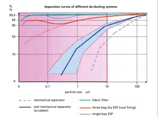
In almost all existing flue gas cleaning concepts and also in those of the future, at least one filtering separator is integrated in the form of a bag filter. If a correct design and execution is provided, this type of separator ensures a very efficient and reliable separation of particles of far more than 99.9 % (Figure 1) [13]. As a result of this, the reliable observance of the range shown in Table 1 for future limit values of < 2 up to 5 mg/Nm³ should be possible.
Figure 1: Efficiency of different particle separators
2.2. Acid crude gases such as HF, HCl and SO
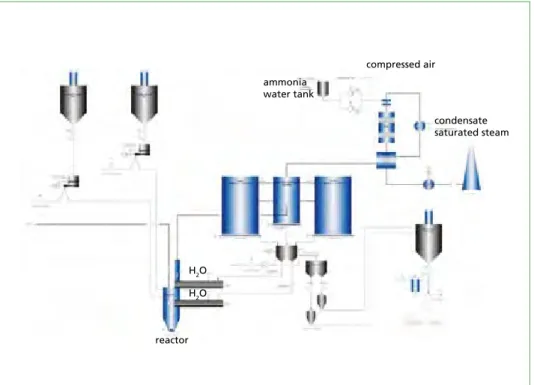
x2.2.1. Lime-based processes Predominantly lime-based processes have so far been used in new plants for the sepa- ration of acid crude gases. Figure 2 shows as an example a design of conditioned dry sorption. Further processes are among other things described in [7].
99.9
Separation curves of different de-dusting systems
η %
99 90
50
10
0
0 0.1 1 10 100
particle size μm
mechanical separator fabric filter
three-bag dry ESP (coal firing) single-bay ESP
wet mechanical separator (scrubber)
reatment
Figure 2: Schematic view of conditioned dry sorption
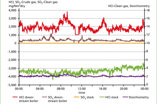
These processes allow the reliable compliance with the today requested limit values, with at the same time acceptable operating costs. Figure 3 [10] shows corresponding crude gas and clean gas values for HCl and SO2 over a period of time of 24 hours.
crude gas
additive additive
AC
filter
clean gas
H2O
double screw conveyer reactor with conditioning rotor Ca(OH)2
08:00 16:00 20:00
2,000 1,000 0 -1,000 -2,000 -3,000 -4,000
HCI, SO2-Crude gas, SO2-Clean gas mg/Nm3dry
00:00 04:00 12:00
-5,000 4,000 3,000
HCI-Clean gas, Stoichiometry
12 10 8 6 4 2 0 18 16 14
00:00 time
HCI down- stream boiler
SO2 down- stream boiler
SO2 stack HCI stack Stoichiometry
Figure 3: Trend curves for HCl and SO2 of WtE-plant GML Ludwigshafen
545 Influence of New WI-BREF on the Concepts of Flue Gas Cleaning in the Future – What Will Change?
Flue Gas Treatment
If particularly for HCl the upper range of BATAELs is requested for the operation of a plant, these requirements can also in the future be achieved with the use of the con- ditioned dry sorption. As a precaution, additional measures for the coverage of crude gas peaks should be integrated in the process concept.
• Injection of an additive powder, as e.g. NaOH, into an evaporative cooler installed upstream of conditioned dry sorption [15]
• Combination spray absorber and conditioned dry sorption [8]
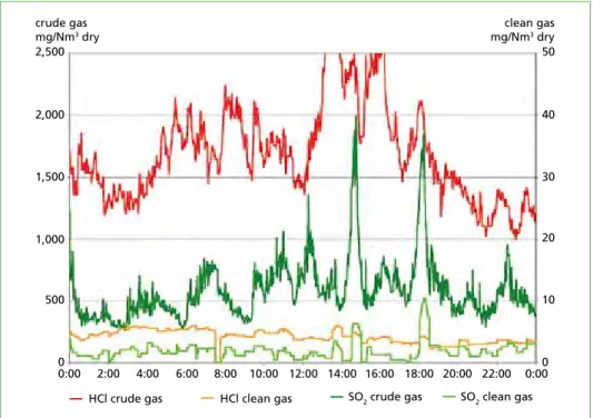
The efficiency of the combination spray absorber with conditioned dry sorption is shown in Figure 4. The corresponding trend curves for crude gas and clean gas values of HCl and SO2 of an incineration line of MHKW Rothensee are illustrated over a period of time of 24 hours. At the time of measurement the limit values complied with the requirements of EU Directive 2000/76/EC [5]. The requested limit values will reliably be observed even in case of a stoichiometric factor lower than 1.8. [8]. To allow the observance of more stringent limit values, the stoichiometric factor should be increased slightly.
As far as lower values have to be considered for HCl and SO2 during design of a new plant, the use of combined processes can be reasonable and/or necessary.
• Combination dry sorption - wet scrubber [11] (see subclause 2.3.2)
• Combination of a dry sorption process using NaHCO3 with a Ca-based process [9]
2,500 crude gas mg/Nm3 dry
clean gas mg/Nm3 dry
2,000
1,500
1,000
00:00 0:000
10 20 30 40 50
2:00
SO2 clean gas 4:00 6:00 8:00 10:00 12:00 14:00 16:00 18:00 20:00 22:00 500
HCl crude gas HCl clean gas SO2 crude gas
Figure 4: Trend curves for HCl and SO2 of WtE-plant MHKW Rothensee
reatment
2.2.2. Dry sorption with NaHCO3
The dry sorption with NaHCO3 competes with process technologies using Ca-based additive powder qualities. The quite simple process technology of the basic variant is shown in Figure 5. Contrary to Ca-based processes, the efficiency will increase with the dry-bulb temperature in the gas when using NaHCO3. The multiple re-circulation of the particles separated in the filter into the flue gas flow upstream filter is advantageous with regard to the separation efficiency and the stoichiometric factor [12].
filter
ID-fan stack mill
crude gas
NaHCO3 AC
top filter
In principle, the current typically requested limit values and the upper values of BA- TAELs can be observed with this process, however, compared to Ca-based processes, with higher costs for the provision of additive powders. Due to the reason above, this process has mainly be used for smaller incineration plants. This process may gain in importance in the future in combination with SCR-plants. The advantage in this con- nection is that NaHCO3 allows an efficient separation of SO2 and HCl from acid crude gases, preferably in the case of higher temperatures. A corresponding process variant is discussed under subclause 2.3.3.: Combination of dry sorption with SCR process.
2.3. Reduction of NO
xIn the draft of WI-BREF, the limit values for NOx are specified in a very wide range.
• New plants
– NOx: 50-120 mg/Nm³ – NH3: 2-10 mg/Nm³
Figure 5:
Basic variant of dry sorption with NaHCO3
547 Influence of New WI-BREF on the Concepts of Flue Gas Cleaning in the Future – What Will Change?
Flue Gas Treatment
• Existing plants
– NOx for SCR 50: 150 mg/Nm³ – NOx for SNCR 50: 180 mg/Nm³ – NH3: 2-10 (SNCR 15) mg/Nm³
With regard to existing plants, this offers the opportunity of further operation of suf- ficiently effective SNCR-systems in the scope of limit values currently valid. Based on the upper values of BATAELs-range, it is still possible to use SNCR-systems for new plants. Regarding the lower range it will surely only be possible to install an SCR-system.
2.3.1. SNCR-process With regard to the investment costs, the SNCR-process constitutes the most cost- effective variant. The achievable emission values with simultaneous observance of requested NH3-slippage are in the order of 80-100 mg/Nm³. In this connection it must be taken into account that the possibility of a correction of emission value to an O2-reference content of 11 vol% is not admissible in all countries of EU. As a re- sult of this, a limit value of 80 mg/Nm³ may correspond to a real emission value of 96 mg/Nm³ if the actual O2-content in the gas totals to 9 vol%.
It has to be expected that in future the use of an SNCR-system alone will no longer be sufficient for a large number of plants. In these cases, either the use of a combined process SNCR with downstream installed scrubber or a process with the use of an SCR-system will become necessary.
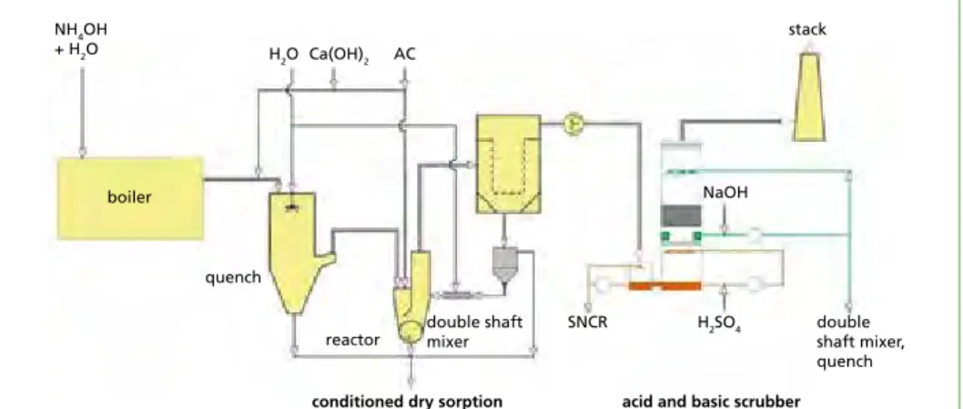
2.3.2. Combination of SNCR – Conditioned dry sorption – Wet scrubber This process combination especially represents an alternative when the requested NOx emission limit values can reliably be kept by means of an SNCR process, however with a higher NH3 emission. The basic design of this combined process is shown in Figure 6.
boiler
quench
reactor
conditioned dry sorption acid and basic scrubber double shaft
mixer
double shaft mixer, quench SNCR H2SO4
NaOH stack AC
Ca(OH)2 NH4OH
+ H2O H2O
Figure 6: Combination conditioned dry sorption – wet scrubber
reatment
In this concept, the conditioned dry sorption is operated in such way that the crude gas downstream of this stage only contains low residual concentrations of acid crude gas pollutants. Depending on the application in question, the downstream installed fine cleaning stage serves for the
• separation of NH3 in an acid scrubber,
• progressing reduction in emission values e.g. for the acid crude gas components,
• heat recovery.
Due to the fact that the acid scrubber only serves as a fine cleaning stage for the re- duction of HCl beside the separation of NH3, the waste water quantity can be kept at a low level. Therefore it will be appropriate to add this waste water above the grate near the incineration.
Figure 7: Emission values exemplary shown at WtE-plant Oulun Energia
To allow an operation free from waste water, the waste water from the basic stage should be added to the system near the conditioned dry sorption.
It may be remarked in addition that when using this combined process, extremely low emission limit values can also be achieved for the acid crude gas pollutants HCl and SOx (Figure 7).
2.3.3. Combined process with the use of SCR
Combination of conditioned dry sorption with SCR process
As far as NOx emission limit values as defined at the lower end of the value range between 50 and 120 mg/Nm³ stated in the draft of WI-BREF have to be observed, the
HOK
®.
Activated lignite. Flue gas adsorbent and catalyst. First choice for gas cleaning in refuse and special waste incineration and metallurgical processes.Substantial reduction of dioxins and furans.
Sometimes, a single, well-considered decision is all it takes:
for the benefit of your company, for the good of the environment.
Rheinbraun Brennstoff GmbH D-50416 Köln Tel.: +49 221-480-25424 www.hok.de
THE HOK SOLUTION
- Solution for waste gas treatment -
®
MIROWEB.NET
Dorfstraße 51
D-16816 Nietwerder-Neuruppin
Phone: +49.3391-45.45-0 • Fax +49.3391-45.45-10 E-Mail: tkverlag@vivis.de
TK Verlag GmbH
order now www. .de
Immission Control
, ThielIMMISSIONSSCHUTZ
4
Thomé-Kozmiensky • Löschau
K.J. Thomé-Kozmiensky Michael Hoppenberg
IMMISSIONSSCHUTZ
– Planung, Genehmigung und Betrieb von Anlagen – Band 1
1
Thomé-Kozmiensky, Hoppenberg , ThielIMMISSIONSSCHUTZ
4
Thomé-Kozmiensky • Löschau
Karl Joachim Thomé-Kozmiensky Matthias Dombert
Wolfgang Rotard Markus Appel
Andrea Versteyl
IMMISSIONSSCHUTZ
– Planung, Genehmigung und Betrieb von Anlagen – Band 2
2
Thomé-Kozmiensky Dombert, V
ersteyl, Rotard, Appel , ThielIMMISSIONSSCHUTZ
4
Thomé-Kozmiensky • Löschau
K.J. Thomé-Kozmiensky Stephanie Thiel
Markus Appel Andrea Versteyl
Wolfgang Rotard
IMMISSIONSSCHUTZ
– Aktuelle Entwicklungen im anlagenbezogenen Planungsprozess und Immissionsschutz
Band 3
3
Thomé-Kozmiensky Versteyl, Thiel, Rotard, Appel , Thiel
IMMISSIONSSCHUTZ
Recht – Anlagenbetrieb – Optimierung – Emission K. J. Thomé-Kozmiensky Margit Löschau
Band 4
IMMISSIONSSCHUTZ
4
Thomé-Kozmiensky • Löschau , Thiel
IMMISSIONSSCHUTZ
Recht – Umsetzung – Messung – Emissionsminderung K. J. Thomé-Kozmiensky Margit Löschau
Band 5
IMMISSIONSSCHUTZ
4
Thomé-Kozmiensky • Löschau
5
Michael Boneß
Messung
Tabelle 1:
Störkomponente Konzentration QE auf die Hg-Messung
SO2 1.000 mg/m2 – 0,065 µg/m3
H2O 30 Vol.-% 0,060 µg/m3
HCI 200 mg/m3 keine QE
NO 300 mg/m3 keine QE
NO2 30 mg/m3 0,090 µg/m3
O2 21 Vol.-% – 0,120 µg/m3
Alle weiteren getesteten QE‘s < ± 0,05 µg/m3
5. Anwendungsbereich des neuen Messverfahrens für die Emissions- und Prozessmessung bei Verbrennungsanlagen Emission
Das neue Messverfahren konnte bereits für die Emissionsüberwachung des Gesamt- anlagen) ohne Leistungseinbußen oder Einschränkungen erfolgreich absolviert.
Für den Standardmessbereich von 0 bis 45 µg/m³ gilt an allen drei Anlagen ein War- tungsintervall von sechs Monaten.
Prozess (Rohgasanwendung)
Aufgrund der einfachen Bauweise und der Gasentnahme ohne zusätzliche Hilfs- und Re- Die Resultate der Testinstallationen zeigen hierbei die Flexibilität des eingesetzten Messver- fahrens, sowohl für den kleinsten Messbereich von 0 bis 10 µg/Nm³, als auch bis in den sehr hohen Konzentrationsbereich von bis zu 4.000 µg/m³ (Bild 10). Eine schnelle, zuverlässige möglich, wieder rot markierte Peak zeigt (Bild 11). Das Messsystem kommt dabei unverän- dert gegenüber der Emissionsmesseinrichtung zum Einsatz und ermöglicht dem Betreiber bzw. unbekannter Zusammensetzung. Im vorliegenden Beispiel an einer kommunalen Hausmüllverbrennungsanlage betrug die Grundlast im Durchschnitt etwa 200 µg/Nm³.
Allerdings traten auch immer wieder Spitzen von bis zu 3.000 bis 4.000 µg/m³ auf, was natürlich entsprechende Maßnahmen für die Gasreinigung, um den Grenzwert von des markierten Peaks verdeutlicht die schnelle Reaktionszeit der Messung sowohl im Anstieg, als auch im Abklingen der Hg-Konzentration (Bild 12).
Sowohl bei Abfallverbrennungsanlagen und insbesondere auch bei Sondermüllver- brennungsanlagen ist das Interesse an diesen Messungen sehr gestiegen. Denn mit der Hg-Rohgasmessung verfügt der Betreiber über eine Überwachung, die zum frühestmög- lichen Zeitpunkt eine mögliche Überladung von Hg für die Abgaswäsche signalisiert und
Messung von Quecksilber
Messung
typischerweise durch SO2 und andere Gaskomponenten bekannt sind, treten bei diesem Verfahren nicht auf (Tabelle 1). Vergleichende Messungen an Anlagen mit bestehenden Quecksilber CEMS zeigen eine hervorragende Übereinstimmung, ebenso im Vergleich zu Optional können für die regelmäßige Qualitätskontrolle der Messungen automatisiert HgCl2-Konzentrationen über eine integrierte Verdampferapparatur aufgegeben werden.
Ejector Messgaszelle 1.000 °C Optik/Detektor Klimagerät Kalibriergas-generator (ohne Abdeckung)
blau= Untergrundmessung;
orange= Hg-Absorptionsmessung Hg-Linienaufspaltung durch Magnetfeld an der Lichtquelle Bild 7: Schrankansicht des kontinuierlichen Quecksilber-Messverfahrens MERCEM300Z (außen und innen)
Bild 9:
Quarzmessgaszelle bei 1.000 °C zur Konvertierung und gleich- zeitigen Echtzeitmessung (pa-
Immissionsschutz, Volume 1 Released: 2010
ISBN: 978-3-935317-59-7 Hardcover: 632 pages Price: 30.00 EUR
Immissionsschutz, Volume 2 Released: 2011
ISBN: 978-3-935317-75-7 Hardcover: 593 pages Price: 30.00 EUR
Immissionsschutz, Volume 3 Released: 2012
ISBN: 978-3-935317-90-0 Hardcover: 664 pages Price: 40.00 EUR Immissionsschutz, Volume 4
Released: 2014
ISBN: 978-3-944310-16-9 Hardcover: 450 pages Price: 40.00 EUR
Package Price
Immissionsschutz, Volume 1 – 5
120.00 EUR
save 80.00 EUR Immissionsschutz, Volume 5
Released: 2015
ISBN: 978-3-944310-23-7 Hardcover: 370 pages Price: 60.00 EUR Editors: Thomé-Kozmiensky (et al.)
551 Influence of New WI-BREF on the Concepts of Flue Gas Cleaning in the Future – What Will Change?
Flue Gas Treatment
installation of an SCR-process will in any case become necessary. In this connection the preferred temperature range for the catalyst lies in a range of 220 °C up to 240 °C. This temperature range allows a sufficiently good transformation speed.
Problems due to the formation of ammonium sulphate can reliably be exclu- ded, as far as the temperature-dependent SO2 content in the gas is lower than 10-25 mg/Nm³. Due to the preferred temperature range for the conditioned dry sorption of approximately 130 °C up to 150 °C, a reheating of gases upstream of the catalyst is unavoidable. The reheating of gases can indeed largely be realised by heat recycling around the catalyst, however, the remaining temperature difference of approximately 30 K has to be balanced by an external heat input, e.g. by means of a steam-gas-heat exchanger. A downstream installed heat exchanger located upstream of stack can be used for the heat recovery, but the generated heat has a comparatively poor quality. Figure 8 shows the basic scheme of a corresponding process.
Figure 8: Combination conditioned dry sorption – SCR
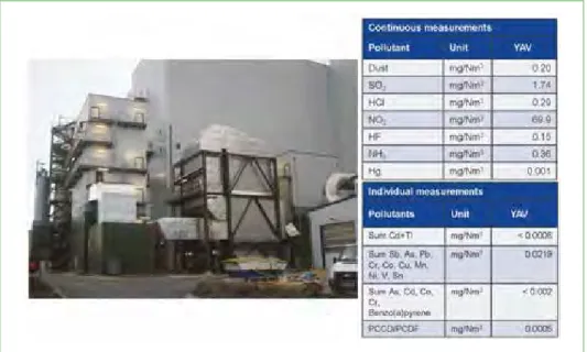
If very low limit values are also requested for further pollutants such as acid crude gas pollutants, heavy metals, dioxins/furans, an additional dry sorption stage can be installed downstream of SCR-system. A correspondingly designed and installed plant including the achieved annual average values are shown in Figure 9. Details concerning this plant concept can be gathered from the references [9].
H2O H2O
reactor
compressed air ammonia
water tank
condensate saturated steam
reatment
Figure 9: Emission values of WtE-plant Enertec Hameln, line 4
Combination of dry sorption with SCR process
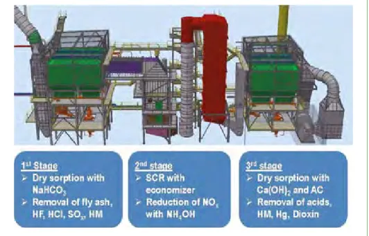
Due to the fact that the separation of acid crude gas pollutants, and in this respect particularly SOx, is very efficiently possible by injection of NaHCO3 in a temperature range of 220 °C up to 240 °C, the reheating can be omitted in case of a combination of dry sorption with NaHCO3 and a downstream installed catalyst. Figure 10 shows a possible process variant.
The separation of acid crude gas pollutants takes place in the first dry sorption stage at a temperature of approximately 240 °C by means of injection of NaHCO3. Following this, the ammonia water injection, the mixing section and the catalyst are arranged.
In an external economiser installed downstream of catalyst, the gas is cooled down to approx. 140-120 °C. Another dry sorption stage serves for the reliable separation of the acid pollutants still existing in the gas, the heavy metals including mercury as well as dioxins/furans by means of injection of Ca(OH)2 and activated carbon. This arrangement does not only allow the achievement of low NOx and NH3 values, but also ensures a very good separation efficiency for acid crude gases with at the same time low additive powder consumption. However, when evaluating the economic efficiency, the high specific purchase price for NaHCO3 has to be compared to the cost savings resulting from the omission of steam-gas-heat exchanger.
The use of a low temperature catalyst can be an alternative to the above-described process. Due to the operation of SCR at approximately 180 °C up to 200° C, activated carbon can be injected in the dry sorption stage. However, this variant presents the high risk of efficiency loss of catalyst stage due to the formation of ammonium salts.
A cyclic regeneration of catalyst by means of gas heating will be necessary.
553 Influence of New WI-BREF on the Concepts of Flue Gas Cleaning in the Future – What Will Change?
Flue Gas Treatment
Figure 10: Process variant for the combination dry sorption with SCR
2.4. Heavy metals as well as dioxins/furans
2.4.1. Heavy metals Where heavy metals (except for Hg and Hg-compounds) are present in gaseous form due to their steam pressure, they can be converted into particulate compounds by means of chemical reactions with the basic additive powder qualities. In case of a sufficient quantity of basic additive powder qualities, a separation reliably takes place even in case of temperatures higher than 200 °C. Measuring results clearly show that emission limit values to be expected in the future for heavy metals can reliably be achieved by means of injection of Ca- or Na-based additive powder qualities in combination with a particle filter.
The separation of Hg and Hg-compounds will in most of the cases be achieved by ad- sorption at additive powders with large specific surface. Usually, activated coke and/
or activated carbon are used for this purpose. Normally the limit value totalling to 10 µg/Nm³ which is already currently requested as annual average value in Germany, can be achieved with this process.
The continuous measurement of Hg limit values already generally required in Ger- many and expected for all other EU countries in the future, has led to the fact that many plants have meanwhile been equipped with precautionary measures for the separation of Hg peaks. In this connection especially the additional injection of do- ped activated carbon in case of increasing emission limit values may be mentioned.
reatment
The injection of additional liquid additive agents into an evaporative cooler installed upstream of the conditioned dry sorption system may present a further measure [6].
Even acid scrubbing stages installed downstream of a condition dry sorption system may contribute to the Hg separation.
2.4.2. Dioxins/furans
The emission limit value for dioxins/furans will intensify significantly as a result of re- vision of WI-BREF (Table 1). There is a large number of measuring results available for the injection of carbonaceous additive powder qualities with large specific surface areas in connection with a bag filter, partly clearly below the range of BATAELs according to Table 1. Nevertheless, individual measurements are also known, showing emission values lower than 0.1 ng/Nm³ which are, however, lying above the upper limit of the reworded BATAELs. In this context a precise operating mode of plant has to be ensured in future in order to avoid an exceeding of emission limit values.
• Low CO-values
• Low particle contents in the clean gas downstream filter
• Adequate injection quantities of carbonaceous additive powder qualities Multi-stage flue gas cleaning systems are surely an advantage in this respect.
It should also be noted that in the scope of revision of WI-BREF the use of continuous sample taking for the constant monitoring of dioxin/furan emissions is being debated.
In this connection experiences are among others available in Belgium.
3. Further major points for discussion concerning WI-BREF
Apart from the emission limit values there are further items which are discussed in the scope of the revision of WI-BREF. The following two major points are discussed in connection with the BATAELs:
Normal operating conditions (NOCs) und others than normal operating conditions (OTNOCs)
According to IED [4], the emission limit values are referring to the normal operating conditions. However, the IED is making an exception with regard to waste incinerators and refers in this context to the effective operating time as basis for the observance of emission limit values. The effective operating time comprises a larger operational range and can also include others than normal operating conditions. Due to the fact that the draft does not provide a clear allocation, there might be a need for discussions in the future concerning the granting of approvals.
The above-mentioned continuous sample taking in connection with dioxins/furans is an example for this. The question arises, when the measurement has to be connected, e.g. during cold start-up of a incineration line, and which further operating conditions will be evaluated as OTNOCs. The discussion has not been finalised in this respect.
555 Influence of New WI-BREF on the Concepts of Flue Gas Cleaning in the Future – What Will Change?
Flue Gas Treatment
Measuring uncertainty Particularly the lower end of BATAEls range is subject to the risk that measuring tole- rances, as requested in the IED, cannot be achieved, thus presenting a high measuring uncertainty for these values (Figure 11).
Figure 11: Measurements uncertainties
It is important to make sure that the new WI-BREF will comprise a definitive clarifi- cation. Based on the current state of discussion, the WI-BREF will contain a reference concerning the observance of the measuring uncertainty. The question, however, re- mains open, whether this reference will also be included in chapter 5 (BAT Conclusions).
Nevertheless this will absolutely be necessary as only this part has to be transferred into national law. [3]
4. Personal assessment
The whole range of BATAELs to be expected in the scope of revision of WI-BREF can reliably be achieved with the available process-related solutions for the flue gas cleaning in the field of waste-to-energy. However, in many cases multi-stage and - in comparison to today’s plants - more complex systems will have to be used. The disadvantage of higher investment costs frequently associated with this, will in many cases be at least partially be compensated by lower operating costs.
It remains to be seen which limit values will each be stipulated in national law as binding values by the separate member states of the EU. Even if, however, the upper end of BATAELs ranges will be taken as basis in this context, the lower values will in all probability be discussed in the scope of public participation during approval pro- cedures for new plants.
From the author’s point of view it will definitely be necessary that not only the BATAELs but also further items will be defined precisely in the final version of WI-BREF and particularly in the BAT Conclusions. This refers among other things to the discussion about measuring uncertainty and to NOC and/or OTNOC.
reatment
Finally, it has to be noted that there are still considerable differences among the member states of the EU concerning the handling of thermally recyclable residues (Figure 12 [2]).
Even if the statistic is based on an investigation in 2015 and although changes have been realised in the meantime in some countries, as e.g. Great Britain and Finland, regarding the reduction of landfilling, the statistic is still correct generally. There is still a large number of countries in which thermally reusable residues, which can no longer be recycled, are partly or completely deposited. With regard to the effects on the environment, the installation of waste-to-energy plants with limit values at the upper end of BATAELs will in this connection surely be better than the further landfilling of these materials, on the grounds that thermal recycling plants are not financially feasible.
Figure 12: Shares of recycling, WTE and landfill in Europe
5. References
[1] Best Available Techniques (BAT) Reference Document on Waste Incineration, Draft 1 (May 2017)
[2] CEWEP: http://www.cewep.eu/wp-content/uploads/2017/08/Graph-3-treatments.pdf [3] Clerens, P.; Walczak, N.: Impact of EU Legislative Developments on the Waste-to-Energy Sec-
tor. In: Thomé-Kozmiensky, K. J.; Thiel, S.; Thomé-Kozmiensky, E.; Winter, F.; Juchelková, D.
(Eds.): Waste Management, Volume 7, Waste-to-Energy. Neuruppin: TK Verlag Karl Thomé- Kozmiensky, 2017, pp. 3-13
[4] European Parliament, European Council: Directive 2010/75/EU of 24 November 2010 on in- dustrial emissions (integrated pollution prevention and control), 2010
Municipal waste treatment in 2016 EU 28 + Switzerland, Norway and Iceland
landfill 25
1 1 1 1 1 3 3
111722 23 2428 31374249 50 515764 667278 81 82 82 92
4 57 27
50 45 51 46 3238
55 53
3436 32 1820 18
1918
21 16 15144 11
3
48 54
4 47 49 54 48 53
6659 4231
4842 45
5751 5044 4030 34 35 30 3223 28 2119 15 178 53
38 33
0 10 20 30 40 50 60 70 80 90 100 shares
%
Germany Sweden
EU-28
Denmark Belgium
Netherlands
AustriaFinland France Italy
Luxemburg United Kingdom
Spain Portugal*
Estonia Slovenia LithuaniaPolandIreland** Slovakia CyprusRomaniaGreece Czech Republic
Malta Hungary Bulgaria LatviaCroatia
SwitzerlandNorw ay
Iceland Waste-to-Energy recycling and composting
557 Influence of New WI-BREF on the Concepts of Flue Gas Cleaning in the Future – What Will Change?
Flue Gas Treatment
[5] European Parliament, European Council: Directive 2000/76/EC of 4 December 2000 on the incineration of waste, Official Journal of the European Communities, 28.12.2000
[6] Fritsche, J.: Aktivkohle AddSorb VQN u. EcoSorb QS Advanata in der Rauchgasreinigung, VDI- Wissensforum Betriebsmittel in der Rauchgasreinigung, Mannheim 2014
[7] Löschau, M.; Kersting, M.: Energieeffizienz bei der Abgasreinigung. In: Thomé-Kozmiensky, K. J.; Beckmann, M. (Eds.): Energie aus Abfall, Band 7. Neuruppin: TK Verlag Karl Thomé- Kozmiensky, 2010, pp. 619-637
[8] Lücker, G.: Optimierung der Sprühabsorption des MHKW Rothensee – Eine Herausforderung?
In: Thomé-Kozmiensky, K. J.; Beckmann, M. (Eds.): Energie aus Abfall, Band 12. Neuruppin:
TK Verlag Karl Thomé-Kozmiensky, 2015, pp. 327-346
[9] Margraf, R.: Dry, Semi-dry or Wet – Which System Fits Best Depending on the Overall Condi- tions? – In: Thomé-Kozmiensky, K. J.; Thiel, S.; Thomé-Kozmiensky, E.; Winter, F.; Juchelková, D. (Eds.): Waste Management, Volume 7, Waste-to-Energy. Neuruppin: TK Verlag Karl Thomé- Kozmiensky, 2017, pp. 431-447
[10] Margraf, R.: Simple and Effective – the Conditioned Dry Sorption Process for Flue Gas Treat- ment Downstream Waste Incinerators. In: Thomé-Kozmiensky, K. J. (Eds.): Waste Management, Volume 5. Neuruppin: TK Verlag Karl Thomé-Kozmiensky, 2015, pp. 253-267
[11] Margraf, R.: TwinSorp® – a simple process for increased requirements on the emission limit values i. a. for waste and RDF incinerators, considering the energy efficiencycommand, 6th symposium; Dry crude gas cleaning for solid fuel firings and thermal process technology, Haus der Technik Essen, 2010
[12] Margraf, R.: Trockensorption mit Natriumbicarbonat – wirklich ein ganz einfaches Verfahren?, Examinations at a waste incinerator in France; 5th symposium, Dry crude gas cleaning for solid fuel firings and thermal process technology, Haus der Technik Essen, 2009
[13] Schulteß, W.: Presentation material Ing.-Büro Prof. Schulteß
[14] Technical Working Group (tWG) Draft conclusions of the Final Meeting or the review of the BAT reference document on Waste Incineration (WI BREF), European IPPC Bureau, Seville, 23.–27. April 2018
[15] Wradatsch, R.: Entwicklung und Betriebserfahrungen mit der konditionierten Trockensorp- tion des MHKW Ludwigshafen, 3. Fachtagung Trockene Abgasreinigung für Festbrennstoff- Feuerung und thermische Prozesstechnik, Haus der Technik Essen, 2007
Contact Person
Ruediger Margraf, Graduated engineer LUEHR FILTER GmbH
Managing director Enzer Straße 26 31655 Stadthagen GERMANY
Phone: 0049 - 57 21 - 7 08 - 2 00 Email: r.margraf@luehr-filter.com
Dorfstraße 51
D-16816 Nietwerder-Neuruppin
Phone: +49.3391-45.45-0 • Fax +49.3391-45.45-10 E-Mail: order@vivis.de
TK Verlag GmbH
order now www. .de
Elisabeth Thomé-Kozmiensky
1.5. Generalunternehmer (Planung und Ausführung) Deutsche Babcock Anlagen GmbH
Kesselerneuerung Von Roll Inova, resp. HITACHI Zosen Inova Turbinenerneuerung
1.6. Genehmigungsbehörde Regierung von Oberfranken Ludwigstraße 20 95444 Bayreuth
1.7. Aufsichtsführende Behörde Bayerisches Landesamt für Umweltschutz Bürgermeister Ullrich-Straße 160 86179 Augsburg 1.8. Inbetriebnahme
1978: Linien 1 + 2 und
Klärschlammbehandlung
1981: Linie 3
1982: Erweiterung um Stromerzeugung 1982-1988: Fernwärmeauskopplung und -verteilung 1990: Feuerraumoptimierung, 1. Erweiterung der Abgasreinigungsanlage 1996: Abgasreinigungsanlage2. Erweiterung der
Bild 3:
Abwasserbehandlung und Schlammentwässerung
Löschwasserbecken Notstrom- aggregate 3+4 Katalysatoren
(SCR)
Gewebefilter Öl- tank
Waage Zentral-lager Grundstücksgrenze
Ausdehnungs- gefäß
Energieteil Abwärmenutzung Heizwerk 1 Abfall- bunker lieferungAn- Klärschlamm- Stapelbehälter
Kessel-hausElektro-filter
Teich Luftkondensator Maschinenhaus für neue Turbine/Generator Wertstoffhof
Stadt Bamberg
Kompostieranlage Kläranlagengelände
AVA Augsburg
3. Abfallaufkommen Abfallarten
Hausmüll: 131.103 t
hausmüllähnlicher Gewerbemüll: 81.835 t
Sperrmüll: 14.204 t
Krankenhausabfälle: 3.363 t
insgesamt: 230.505 t
4. Kapazität, Durchsatz und Geometrie Kapazität (Auslegung) 255.000 t/a davon
• Siedlungsabfälle: 251.500 t/a
• Krankenhausabfälle: 3.500 t/a bei einem Heizwert von 9,2 MJ/kg Durchsatz (Siedlungsabfälle)
Durchsatz 2014: 238.224 t
Durchsatz 2013: 236.693 t
Durchsatz 2012: 233.888 t
Durchsatz (Krankenhausabfälle)
Durchsatz 2014: 3.363 t
Durchsatz 2013: 3.097 t
Durchsatz 2012: 3.257 t
Abmessungen des Baukörpers 235.000 m2
Bauhöhe ohne Kamin: 38 m
5. Anlieferung und Lagerung Abfallanlieferungen mit: LKW
~ 35.000 Anlieferungen/Jahr 5.1. Waage Hersteller:
Bauart: Brückenwaage
Anzahl: 3
5.2. Anlieferungshalle/Entladestation Anzahl der Abkippstellen: 12 5.3. Bunker für feste Abfälle Abfallart: Siedlungsabfälle Maße (l x b x h) 55 m x 13 m x 25 m nutzbares Volumen: 10.000 m3
Nutzmasse: ~ 5.000 t
Anzahl der Abkippstellen: 12 Abfallart: Krankenhausabfälle nutzbares Volumen: 5.000 m3 5.4. Bunker für Schlacken nutzbares Volumen: ~ 500 m3
5.5. Betriebsmittellagerung
Heizöl: ~ 80 m3
Ammoniakwasser: ~ 60 m3
Kalksilo: ~ 50 m3
Natronlauge: ~ 50 m3
Bild 4: Müllfahrzeuge beim Abkippen von Abfall in Müllbunker Bild 5: Schlackehalle der AVA Augsburg
Waste-to-Energy Plants
– Germany –
The actual book 2016|2017 carries forward the survey of waste-to-energy plants in the Federal Republic of Germany which started in the 1990´s. With the first publication we have two books which complement each other perfectly. Both books provide extensive information about the installed technology and the environmental impact of the waste-to-energy plants. The quality of the new inquiry has been extended in terms of the technical data. Existing gaps regarding the data were partially filled.
This is the result from the considerable assistance of numerous plant operators. The publication on hand shall be seen as an interims report. The work on the data acquisition will be continued. For this reason we ask plant operators and manufactures to critically review the release data.
• 33 minucipal solid waste incineration plant
• 7 solid recovered fuel power plant
• 1 Sonderabfallverbrennungsanlage
The further investigations will be extended to the missing German waste-to-energy plants as well as to plants in other countries.
2014 | 2015
ISBN: 978-3-944310-26-8 Hardcover: 581 Pages,
with coloured illustrations Price: 45.00 EUR
2016 | 2017
ISBN: 978-3-944310-38-1 Hardcover: 407 Pages,
with coloured illustrations Price: 68.00 EUR
ABFALLVERBRENNUNGSANLAGEN – Deutschland –
2014 | 2015 Elisabeth Thomé-Kozmiensky
Editor: Elisabeth Thomé-Kozmiensky
ABFALLVERBRENNUNGSANLAGEN – Deutschland –
2016 | 2017 Elisabeth Thomé-Kozmiensky – Deutschland –
– Deutschland – – Deutschland –
Vorwort
4
Bibliografische Information der Deutschen Nationalbibliothek Die Deutsche Nationalbibliothek verzeichnet diese Publikation in der Deutschen Nationalbibliografie; detaillierte bibliografische Daten sind im Internet über http://dnb.dnb.de abrufbar
Thiel, S.; Thomé-Kozmiensky, E.; Winter, F.; Juchelková, D. (Eds.):
Waste Management, Volume 8 – Waste-to-Energy –
ISBN 978-3-944310-42-8 Thomé-Kozmiensky Verlag GmbH
Copyright: Elisabeth Thomé-Kozmiensky, M.Sc., Dr.-Ing. Stephanie Thiel All rights reserved
Publisher: Thomé-Kozmiensky Verlag GmbH • Neuruppin 2018 Editorial office: Dr.-Ing. Stephanie Thiel, Dr.-Ing. Olaf Holm,
Elisabeth Thomé-Kozmiensky, M.Sc.
Layout: Janin Burbott-Seidel, Ginette Teske, Roland Richter, Cordula Müller, Sarah Pietsch, Gabi Spiegel, Lena Bischkopf
Printing: Universal Medien GmbH, Munich
This work is protected by copyright. The rights founded by this, particularly those of translation, reprinting, lecturing, extraction of illustrations and tables, broadcasting, micro- filming or reproduction by other means and storing in a retrieval system, remain reserved, even for exploitation only of excerpts. Reproduction of this work or of part of this work, also in individual cases, is only permissible within the limits of the legal provisions of the copyright law of the Federal Republic of Germany from 9 September 1965 in the currently valid revision. There is a fundamental duty to pay for this. Infringements are subject to the penal provisions of the copyright law.
The repeating of commonly used names, trade names, goods descriptions etc. in this work does not permit, even without specific mention, the assumption that such names are to be considered free under the terms of the law concerning goods descriptions and trade mark protection and can thus be used by anyone.
Should reference be made in this work, directly or indirectly, to laws, regulations or guide- lines, e.g. DIN, VDI, VDE, VGB, or these are quoted from, then the publisher cannot ac- cept any guarantee for correctness, completeness or currency. It is recommended to refer to the complete regulations or guidelines in their currently valid versions if required for ones own work.