LOWERING COSTS WITH DATA TRANSPARENCY.
What use is the technologically advanced gas purification if gas concentrations in raw gas cannot be detected quickly ‒ hydrochloric acid, sulfur dioxide and even mercury? With accurate measured values within 30 seconds, the rugged and corrosion-resistant MCS300P HW and MERCEM300Z gas analysis systems from SICK really impress. Gas concentration changes are displayed in a timely manner and simplify the control to keep concentrations below requested emission limit values. Even peaks are safely detected. The quick measurement results also help reduce costs: From now on, only the chemical consumption actually needed for the process has to be considered. We think that’s intelligent. www.sick.com/waste
Sewage Sludge
Possibilities to Integrate Sewage Sludge Incineration into Municipal Solid Waste Incineration Facilities
Wolfgang Schüttenhelm
1. Overview of integration possibilities ...504
1.1. Organisational synergies ...504
1.2. Infrastructural synergies ...505
1.3. Process synergies ...505
2. Sludge storage and drying, incineration, boiler and water steam cycle ...507
3. Flue gas cleaning, supply of utilities and emission monitoring ...509
4. Integration of alternative processes ...512
5. Summary ...514
6. Literature ...514 In future the agricultural use of sewage sludge by means of disposal on fields will be not possible anymore. Switzerland as well as The Netherlands have already stopped this agricultural use of sewage sludge as a fertilizer. Germany revised its Fertiliser Regulation (Düngemittelverordnung DüMV) by means of introducing new and more stringent limit values for numerous substances. Thus, the agricultural use will be prohibited with first effects from 2019 onwards. Moreover, Germany enforced its revised Sewage Sludge Regulation (AbfKlärV) on October 5, 2017 requiring phosphorus recovery for larger cities with 100,000 personal units or more from 2029 and for medium size cities with 50,000 personal units or more from 2032. Phosphorus has already become a rare resource. In 2017, the EU commission included it on the list of Critical Raw Materials for the EU [1]. Therefore, its recovery from waste streams is the most sustainable way to secure its availability. An overview about the current legal situation is summarized in [2].
Today, co-incineration of sewage sludge in coal-fired power stations, cement kilns and waste-to-energy plants is still a widely applied method in Germany to avoid disposal of sewage sludge. Moreover, its energy content is recovered. However, this route is not any longer viable as soon as phosphorus recovery gets legally mandatory. Due to the ban of sludge disposal and phosphorus recovery, sludge incineration plants have to be installed.
Actually, the long-term proven fluidized bed technology is the preferred thermal treat- ment technology for this application. Besides, other processes being based on rotary kiln technology, pyrolysis and gasification are options. First references already exist including small-scale demonstration plants. Others are still under development or testing [5].
Sewage Sludge
Planning of many new mono-incineration units has already been started in order to be ready for operation in 2022/2023. Some are already under construction. Economically, it is in most cases advantageous to install new units at existing power plant sites due to the existing infrastructure provided that enough space is available.
This paper is focusing on the possibilities how to integrate new mono-sludge incin- eration units at existing waste-to-energy sites in order to optimise the overall envi- ronmental and economical synergies. Of course, similar synergies can be achieved by means of integration with other existing sites such as heating power plants. Depending on site-specific constraints the achievable benefits of such an integration have to be determined.
1. Overview of integration possibilities
Obviously, there are several different fields of integration possibilities which are offering benefits for both the respective citizens as well as the owners of the plant. As a result the cost for waste water treatment shall be effected as little as possible.
The different fields impacting the optimal plant integration can be split into
• organisational synergies,
• infrastructural synergies, and
• process synergies.
All those potential synergy options together provide the possibility to reduce the ad- ditional waste water treatment cost as much as possible. They are depending on each other (Figure 1). Of course, especially the existing infrastructure needs to be carefully analysed in order to determine and evaluate bottlenecks. The need for upgrades and extensions has to be considered in line with a total cost approach.
optimal integration
process / technology
organisation infrastructure
Figure 1:
Fields of synergies for optimal plant integration
1.1. Organisational synergies
First of all, each existing site is managed by means of an experienced site management.
The site management as well as the site’s staff is familiar with the operation of firing systems, boilers, flue gas cleaning plants, water steam cycles as well as turbines and/or
Sewage Sludge
heat production systems and the electric and control system. They are able to manage and operate the new sludge treatment facility, too. Training of new staff for the new sludge incineration facility will be faster as the existing staff will support them with their expertise. Moreover, existing staff e.g. at the weighbridge, in the laboratory or in the workshops of the waste-to-energy plant will also provide their services to the sewage sludge incineration unit. Furthermore, the same management and administration will be able to manage and operate the plant while only adding a minimum of new people.
Secondly, permit application will be easier as authorities are familiar with the site and established communication paths are in place.
Last but not least the sales, procurement and IT departments of the existing waste-to-en- ergy plant also shall serve the new sludge incineration facility. Existing maintenance contracts can be used to reduce operation and maintenance costs e.g. during revisions for boiler cleaning or scaffolding works.
1.2. Infrastructural synergies
Usually, waste-to-energy sites are located in industrial areas. They are connected to the road system, some of them have rail or waterway access. Streets, rails, jetty to load/
unload barges, gates and fences are already existing. Water supply and waste water lines are available as well as the access to the electricity grid and, potentially, the connection to district heating networks. The latter is very important since increasing the district heating output will result not only in a very important additional source of income, but would also provide a valuable contribution to a sustainable operation.
A weighbridge as well as labs and workshops are also already installed. Moreover, the supply of chemicals and absorption agents such as hydrated lime, sodium bicarbonate or activated carbon as well as transport of residues are organized. The joint supply for the enlarged plant will grant not only better prices, but common silos and tanks can be used as well.
In addition, utilities supply systems for heating steam, boiler feed water and compressed air as well as cooling water are in place. Depending on their original design some extension might be required. Site transportation tools such as forklifts and cleaning equipment are at site and can also be used for the new sludge incineration unit.
Last but not least social rooms such as washroom facilities and meeting rooms are already installed.
To sum up, such infrastructural synergies are resulting in a considerable contribution to improved economics of a new sludge incineration project.
1.3. Process synergies
Whereas organizational and infrastructural synergies are always applicable, process synergies strongly depend on the design of the installed waste-to-energy units. It has to be investigated to which extend an integration is possible subject to required avail- ability, throughput and lifetime of all systems and whether the emissions will be met
Sewage Sludge
as before. Especially, if the existing plant is only consisting of one unit the degree of dependency on each other will become strong and has to be carefully evaluated. The analysis process should address at least the following items:
• Furnace/boiler: capacity, heating values, flue gas velocities and temperatures, steam temperatures;
• Turbine and water steam cycle: capacity, steam temperatures, ND extraction capac- ity, condensate and feed water re-heating system, feed water preparation;
• Flue gas cleaning: capacities, design of all components focusing on SO2 removal, ammonia removal, mercury control;
• Supply and storage systems of operation agents and withdrawal of residues: Design and residence time of common systems, common silos, common loading and un- loading facilities;
• Stack: common stack and common emission monitoring equipment/platform;
• Electrical supply system: spare capacities of the existing system including feeders, transformers and switch gears.
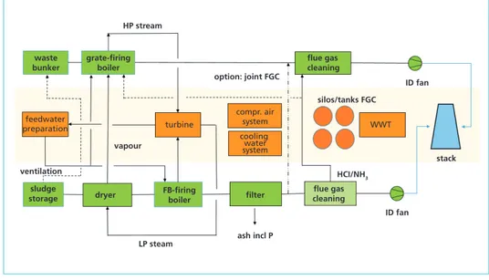
Figure 2 is providing an overview of possible integration options which should be investigated. The main processes of both incineration plants are described: the WtE process line is shown on the top, the common systems are located below and the main processes of the new sludge incineration line are shown on the bottom of Figure 2.
waste bunker
grate-firing boiler
HP stream
option: joint FGC
vapour ventilation
dryer sludge
storage FB-firing
boiler
LP steam ash incl P
HCI/NH3
ID fan
stack ID fan silos/tanks FGC
flue gas cleaning
filter flue gas
cleaning compr. air
system cooling water system turbine
feedwater
preparation WWT
Figure 2: Integration options between WtE and sewage sludge units
Within the following chapters the most important integration options will be described.
Sewage Sludge
2. Sludge storage and drying, incineration, boiler and water steam cycle
Since sludge can be delivered in different qualities the sludge storage and pre-treatment systems are the first process steps to look at. Usually, the incoming sludge is mechanically dewatered to a degree of approx. 20 to 35 wt.% dry substance. Typically, 24 to 28 wt.% are defined as design basis of the downstream processes. The heating value of the mechanically dewatered sludge is approx. 1 to 2 MJ/kg only. In order to establish a stable combustion process by means of the fluidized bed the sludge has to be further concentrated to a content of approx. 85 wt.% dry substance or more increasing its heating value to approximately 10 to 12 MJ/kg. Therefore, thermal drying is required. Different types of dryers can be used, but all of them need steam for heating of the feed material and evaporation of the water. Alternatively, dried sewage sludge can be supplied to the sludge incinerator.
The mechanically dewatered sludge is emptied into a sludge bunker which has to be ventilated. The exhaust usually has to pass a filter system to avoid odour emissions. This ventilation can be combined with the waste bunker ventilation of the WtE units. The ventilation of the waste bunker area is secured by means of the combustion air fans of the waste incineration units. The secondary or primary air fans sucking in the required combustion air. All odour forming substances are destroyed in the combustion zone.
The second main process step is sludge drying. The sludge dryers can be heated by means of low or medium pressure steam being available from the WtE plant’s water steam circuit. It has to be checked whether enough LP steam can be provided and whether the extraction capacity of the WtE’s turbine is sufficiently designed. The boiler of the sludge incinerator can be designed to produce also high pressure steam with the identical steam parameters of the WtE units – mostly 40 bar, 400°C – which is in fact a very positive effect because low pressure steam only will be supplied to the sludge incinerator. Consequently, the efficiency of the drying process is increased as additionally, electricity will be produced instead of just using the steam from the boiler of sludge incinerator for sludge drying.
parameter
typical concentrations municipal
waste water
vapour from sew- age sludge drying mg/l
COD 200 – 1,500 100 – 10,000
BOD5 100 – 700 up to 3,000
Ntot 20 – 120 200 – 2,500 NH4-N 1)
Ptot 2 – 15 up to 30
pH-value 6.5 – 10 8 – 10
Table 1: Comparison of the composition of municipal waste water with vapours from sewage sludge drying
1) Convection-type drying: approx. 500 mg/l, Contact-type drying:
approx. 2,000 – 3,000 mg/l expected
Since the water steam cycles of all units are combined a common feed water prepara- tion and feed water heating system can be optimized. Existing district heating con- nections can be used for all units increasing the overall flexibility and output.
Besides, dried sewage sludge vapours are the second product of the drying process.
As these vapours are contaminated it is not permitted to release them without treatment into the sewer. The typical range of those contaminated substances are shown in Ta- ble 1. For comparison reasons their content in municipal waste water is added.
Sewage Sludge
Mainly ammonia compounds but also organic and biological active compounds do not permit a simple treatment. Processing of the vapour usually requires the following process steps:
• condensation,
• precipitation and thickening,
• filtration (AC addition, if required), and
• NH3-stripping
Finally, the cleaned condensate will be discharged into the receiving water. However, such a comprehensive treatment is only required in case of non-integrated sludge treat- ment facilities. As a major synergy, the untreated vapours can directly be passed into the WtE combustion system. Since the temperature in the combustion area is above 850°C all organic pollutants will be thermally destroyed.
Provided that the addition of the vapour is occurring at the correct temperature range for the SNCR process (Selective Non Catalytic Reduction) its ammonia content can already be reduced by reacting with NOx from the WtE unit. Consequently, some amount of the reduction agents ammonia or urea for NOx control could be saved. However, this situation needs to be carefully analysed.
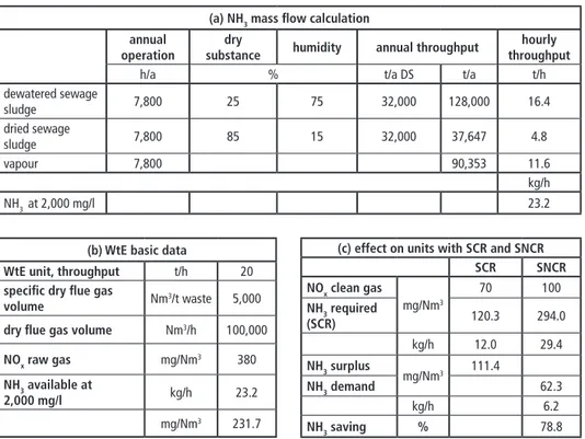
Table 2: Effect of NH3 in vapour (a) NH3 mass flow calculation (b) WtE basic data (c) Effect on units with SCR and SNCR
(a) NH3 mass flow calculation annual
operation
dry
substance humidity annual throughput hourly throughput
h/a % t/a DS t/a t/h
dewatered sewage
sludge 7,800 25 75 32,000 128,000 16.4
dried sewage
sludge 7,800 85 15 32,000 37,647 4.8
vapour 7,800 90,353 11.6
kg/h
NH3 at 2,000 mg/l 23.2
(b) WtE basic data
WtE unit, throughput t/h 20
specific dry flue gas
volume Nm3/t waste 5,000
dry flue gas volume Nm3/h 100,000
NOx raw gas mg/Nm3 380
NH3 available at
2,000 mg/l kg/h 23.2
mg/Nm3 231.7
(c) effect on units with SCR and SNCR
SCR SNCR
NOx clean gas
mg/Nm3
70 100
NH3 required
(SCR) 120.3 294.0
kg/h 12.0 29.4
NH3 surplus
mg/Nm3 111.4
NH3 demand 62.3
kg/h 6.2
NH3 saving % 78.8
Sewage Sludge
Table 2 (a) to (c) presents a sample calculation which shows the effect of feeding the vapour of a sludge dryer into one single WtE unit of 20 t/h throughput. Assuming an average ammonia content of 2000 mg/l the ammonia mass flow rate is 23.2 kg/h respectively 231.7 mg/Nm3 (dry). This ammonia mass flow rate of the vapour is based on a typical sludge incinerator capacity of 32,000 t (DS)/a producing about 11.6 t/h vapour.
In case of a WtE unit with a SCR for DeNOx control this amount of ammonia will already be higher than the required reduction agent amount. The calculated ammonia surplus is 111.4 mg/Nm3, usually a slip of only 5 to 10 mg/Nm3 is permitted at the stack emission monitoring system. However, this calculation does not consider all reactions in the furnace. A part of the ammonia might be converted to N2 and NOx by means of oxidation. Alternatively, already some NH3 will react with NOx to harmless N2 and H2O. Nonetheless, the effect of ammonia has to be taken into account when feeding the dryer vapours or vapour condensate into a WtE furnace. Mass balancing shows that the amount of WtE flue gas should be larger which is certainly true for multi-unit plants.
This is especially valid for dry or semi-dry flue gas cleaning systems. Wet systems will be able to remove the ammonia slip in acid scrubbers.
WtE units of the same capacity with SNCR systems require an over-stoichiometric amount of ammonia to control NOx to the desired clean gas value. Looking at the above sample case the vapour from the dryer will almost contain the required ammonia mass flow rate reducing the amount of purchased ammonia by about 78 %. It has to be noted that this figure is of theoretical nature because the performance of a high efficient SNCR also requires a well-defined flow of ammonia as well as an excellent distribution of the reduction agent in the furnace. Thus, a more complex integration of vapour injection and the SNCR is necessary. In [9] a sample of a high performance SNCR system with low NOx emissions is described which applies a dual injection system.
Besides, the effect of introducing the additional amount of water into the combustion zone needs to be evaluated. The wet flue gas volume will increase depending on the amount of the over-taken vapour. The additional flue gas will result in higher flue gas velocities which might impact the heat exchange and the erosion behaviour of all heat exchanger surfaces. A detailed design check of the boiler has to be executed in order to decide how much vapour can be integrated. Alternatively, the waste throughput would have to be reduced by some percentage.
3. Flue gas cleaning, supply of utilities and emission monitoring
The composition of the sewage sludge significantly differs from the composition of municipal waste. These differences have an impact on the design of the flue gas clean- ing system. Consequently, each existing process step has to be individually analysed whether it can be used without any adaptation or whether a modification is required.
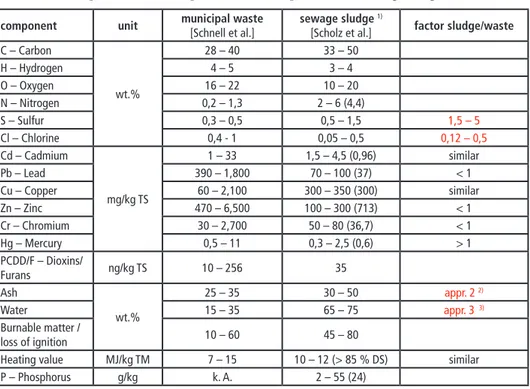
Table 3 shows a comparison of typical compositions and their expected variation ranges.
Sewage Sludge
Table 3: Comparison of the composition of municipal waste and sewage sludge component unit municipal waste
[Schnell et al.]
sewage sludge 1)
[Scholz et al.] factor sludge/waste C – Carbon
wt.%
28 – 40 33 – 50
H – Hydrogen 4 – 5 3 – 4
O – Oxygen 16 – 22 10 – 20
N – Nitrogen 0,2 – 1,3 2 – 6 (4,4)
S – Sulfur 0,3 – 0,5 0,5 – 1,5 1,5 – 5
Cl – Chlorine 0,4 - 1 0,05 – 0,5 0,12 – 0,5
Cd – Cadmium
mg/kg TS
1 – 33 1,5 – 4,5 (0,96) similar
Pb – Lead 390 – 1,800 70 – 100 (37) < 1
Cu – Copper 60 – 2,100 300 – 350 (300) similar
Zn – Zinc 470 – 6,500 100 – 300 (713) < 1
Cr – Chromium 30 – 2,700 50 – 80 (36,7) < 1
Hg – Mercury 0,5 – 11 0,3 – 2,5 (0,6) > 1
PCDD/F – Dioxins/
Furans ng/kg TS 10 – 256 35
Ash
wt.%
25 – 35 30 – 50 appr. 2 2)
Water 15 – 35 65 – 75 appr. 3 3)
Burnable matter /
loss of ignition 10 – 60 45 – 80
Heating value MJ/kg TM 7 – 15 10 – 12 (> 85 % DS) similar
P – Phosphorus g/kg k. A. 2 – 55 (24)
1) In brackets: values from 2006, heavy metals: decreasing tendency up to then
2) Stationary fluidized bed units: Particulate concentration downstream boiler will increase by a factor of 20 – 30 in comparison with a WtE grate based firing system
3) Typical flue gas humidity of a mono sludge incinerator: 30 – 50 Vol.%
Source: Schnell, M.; Horst, T.; Quicker, P.: Thermische Verwertung von Klärschlamm – Überblick und Einordnung bestehender Verfahren. In: Holm, H.; Thomé-Kozmiensky, E.; Quicker, P.; Kopp-Assenmacher, S. (Eds.): Verwertung von Klärschlamm.
Neuruppin: TK Verlag, 2018
Scholz, R.; Beckmann, M.; Schulenburg, F.: Abfallbehandlung in thermischen Verfahren. Leipzig/Wiesbaden: Verlag B. G. Teubner, Reihe Umwelt, 1. Aufl., 2001
Due to the future need of phosphorus recovery the particulates have to be removed in a first step. Electrostatic precipitators or fabric filters can be employed. The dedusted flue gas has to be treated in either a separate new flue gas cleaning unit or it has to be cleaned in the existing flue gas cleaning system together with the exhaust gases from the WtE units. Flue gas concepts downstream of new sludge incineration units are presented e.g. in [7].
As indicated in Table 3 the main differences of the flue gases are
SO2: A much higher SO2 content. SO2 concentration of 3,500 to 4,500 mg/Nm3 are to be considered. The SO2 flue gas concentration of waste to energy plants is usually between 200 to 500 mg/Nm3 for pure municipal waste. Up to 1,000 or even 2,000 mg/Nm3 SO2 is possible, if industrial waste or so-called RDF (refuse derived fuel) is burnt. Due to this increase of SO2 the existing removal system has to be checked. In any case the amount of absorbent has to be increased. Dry systems with the adsorbent NaHCO3 (sodium bicarbonate) are only requiring more adsorbent, lime based systems are closer at the limits. The increased humidity is supporting. Wet scrubbers usually are very flexible.
Sewage Sludge
However, retrofit measures such as additional spray levels (Figure 3), wall rings or trays are cost-efficient measures to scope with the increased SO2-input.
double full cone nozzles
HCl: A much lower HCl content. Usually, it is ranges from 100 to 300 mg/Nm3 instead of 1,000 to 1,500 mg/Nm3. These are typical values for WtE applications. They can increase up to 3,000 mg/Nm3 in case of co-incineration of industrial waste or RDF incineration. Due to the low additional HCl input from the sludge incineration there is no need to modify the existing flue gas systems.
Mercury (Hg): The mercury concentrations in the exhaust gas of WtE plants as well as sludge incineration plants are on a similar level. However, due to the low halogen content of the sludge most of the mercury exists as elemental species which is more difficult to control. Standard activated carbon or mercury precipitation additives control oxidized mercury very well, but have limitations in controlling elemental mercury. In a combined flue gas the additional elemental mercury will be diluted and the existing treatment processes should be sufficient. However, halogenated activated carbons which are more suitable to adsorb elemental mercury might be required to a larger extent.
NOx/NH3: The nitrogen content of the sludge is much higher compared to the one in the waste. Furthermore, the Nitrogen exists in the form of ammonia compounds. Their main origin are fertilizers. Therefore, a certain amount of ammonia is transferred into the vapours of the sludge dryer which is integrated into the WtE furnace. Thus, an in- creased amount of ammonia is to be considered in the raw gas, see Chapter 2. Preferably, a wet scrubbing system including an acid scrubbing stage should be in place in order to absorb possible ammonia slip. Alternatively, a dry system with downstream SCR is beneficial to reduce ammonia from the sludge incinerator. In case of a separate flue gas treatment system of the sludge incinerator, ammonia separation has to be considered as part of the flue gas cleaning system.
N2O: Besides NOx another pollutant might be generated by means of a fluidized bed.
At low bed temperatures, especially less than 850 °C, larger amounts of N2O can be produced. It is not possible to control this amount in the conventional flue gas cleaning systems. Therefore, the combustion process including temperature must be adapted to minimise N2O formation.
Figure 3:
New spray level installed to im- prove SO2 removal
Source: Rasche, D.: Optimierung der Abscheideleistung der nassen Rauchgas- reinigung einer Klärschlammverbren- nung. Vortrag auf dem VDI Wissens- forum Rauchgasreinigung, Düsseldorf, 20.11.2018
Sewage Sludge
Water content: Due to the high water content of 30 to 50 % of sludge incineration flue gases special care has to be taken in respect to water and acid saturation temperatures.
In case of an integration of the flue gases of a sewage sludge incinerator into existing flue gas cleaning lines it is also necessary to analyse whether the additional flue gas volume can be incorporated. For the sample case being presented in Table 2 with a capacity of 4.5 t TS/h about 21,000 Nm3/h dry respectively 33,000 Nm3/h wet have to be treated. The water content of about 32 % is only based on the assumption that the vapours are fed into the WtE combustion zone(s). Single line unit plants most probably will not have the option to increase the flow of the existing flue gas cleaning plant by such an amount corresponding to 25 to 30 % of the original flue gas flow. However, distributing the additional flue gas to e.g. three lines of 100,000 to 120,000 Nm3/h wet flue gas can be possible. The capacity of each line would only be increased by about 8 to 10 %. Of course, the design of the existing equipment needs to be checked. Especially, the capacity of the I.D fans might be a bottleneck requiring at least an upgrade of the motor and/or the frequency converter. In summary, such an integration is very cost efficient if the existing units have spare capacity available or if they are actually not operated at full capacity.
With regard to the conceptional design of new and existing plants the revision of the EU BREF has to be taken into account which is expected to be transferred into the respective country legislation at the end of 2019. Additional challenges for the flue gas cleaning design have to be considered [8].
Even in case of a separate flue gas cleaning line there are several options to save costs by means of integration:
The existing storage and preparation systems such as silos, mills and tanks for supplying additives like sodium hydrogen carbonate, hydrated lime, lime or sodium hydroxide as well as activated carbon, ammonia or urea storage system can be also used for the new sludge incineration line.
Furthermore, the flue gas cleaning residues can be stored and unloaded in common silos. In wet systems the small purge stream from the acid scrubber is disposed by means of injection into the furnace of the WtE units.
Last but not least it might be possible to add a new flue gas stack pipe to an existing stack of a WtE plant. Then, the existing platform for emission monitoring and meas- uring can be used without installing a complete new stack system.
4. Integration of alternative processes
As mentioned before, there are different processes existing besides the standard ap- proach to treat sewage sludge by means of fluidized bed incinerators.
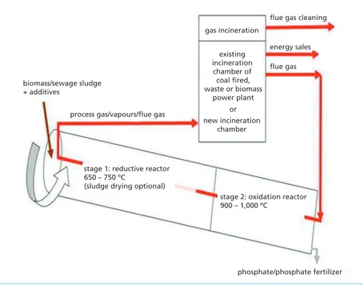
Since several years, a thermal sludge treatment plant has been installed and operated at Oftringen, Switzerland using the so-called Euphore process (Figure 4). It is a sample of high integration of drying, incineration, heat recovery and flue gas cleaning. A rotary
Sewage Sludge
kiln is installed close to the WtE unit serving for a combined process of drying and pyrolysis of the sewage sludge. Hot flue gas is extracted from the upper part of the first pass of the WtE unit. It is introduced in counterflow to the sludge into the end of the rotary kiln. The sludge is added at the other side of the rotary kiln. Due to the incom- plete combustion a synthesis gas is produced which is re-entered into the combustion zone of the WtE unit. There, it will be completely oxidized while also using its energy content in the WtE boiler.
The combined flue gas resulting from both the combustion of the waste as well as of the sewage sludge treatment is passing the boiler and the flue gas cleaning system. The ash content is comparable with the one of the waste combustion as in contrast to the fluidized bed process no sand is required. In addition, a part of the ash including the phosphorus content is withdrawn at the bottom outlet of the rotary kiln.
Other considerations in regards to the increased water content as well as the different pollutant content are similar compared to the integration of fluidized bed process with WtE units, see Chapters 2 and 3. Since the total mercury is mixed in the flue gas with the rather high content of HCl most of it will be oxidized in the same way as the mer- cury originating from the waste. Therefore, removal of mercury will not be different from conventional WtE units.
stage 2: oxidation reactor 900 – 1,000 ºC
stage 1: reductive reactor 650 – 750 ºC
(sludge drying optional)
existing incineration
chamber of coal fired, waste or biomass
power plant or new incineration
chamber gas incineration
flue gas cleaning
energy sales flue gas biomass/sewage sludge
+ additives
process gas/vapours/flue gas
phosphate/phosphate fertilizer
Figure 4: Euphore sewage sludge treatment process
Source: Hazard, B.; Jaborning, S.; Wutscher, K.; Zepke, F.: The Eurhore Process for the Disposal of Sewage Sludge with Co-current Recovery of Phosphorus. Vortrag auf der European Biosolids and Organic Resources Conference, Leeds, 2018
Sewage Sludge
5. Summary
The integration of a new sewage sludge incinerator at an existing waste to energy site offers a lot of synergies reducing the cost and environmental impact in comparison to a separate installation. These synergies are available in different fields starting at the existing organisation and infrastructure up to the use and/or combinations with the existing waste to energy plant.
Most promising process synergies are the combination of the sludge drying process with the incineration plants. Low pressure steam from the site’s water steam cycle can be used for drying and the vapours can be introduced into the furnace(s) of the WtE unit(s) in order to avoid condensation and a separate vapour treatment. Further syn- ergy potential is available for the flue gas treatment. Even if a separate flue gas cleaning system has to be installed common supply and utility systems can be applied.
However, the careful and comprehensive analysis of the existing equipment and pro- cesses is the pre-condition to achieve the target: a cost efficient and environmentally sustainable overall solution.
6. Literature
[1] EU Commission: Communication from the Commission to the European Parliament, the Coun- cil, the European Economic and Social Committee and the Committee of the Regions on the 2017 list of critical materials for the EU. Brussels: 13.09.2017, COM(2017), 490 final
[2] Gutjahr, M.; Müller-Schaper, J.: Treatment of Sewate Sludge in Europe: Status Quo and Perspec- tives of Energy and Phosphorus Recovery – Illustrated by the Example of Selected Countries. In:
Thiel, S.; Thomé-Kozmiensky, E.; Winter, F; Juchelková, D. (Eds.): Waste Management, Volume 8. Neuruppin: TK Verlag, 2018
[3] Hazard, B.; Jaborning, S.; Wutscher, K.; Zepke, F.: The EURHORE Process for the Disposal of Sewage Sludge with Co-current Recovery of Phosphorus. Vortrag auf der European Biosolids and Organic Resources Conference, Leeds, 2018
[4] Rasche, D.: Optimierung der Abscheideleistung der nassen Rauchgasreinigung einer Klärschlam- mverbrennung. Vortrag auf dem VDI Wissensforum Rauchgasreinigung, Düsseldorf, 20.11.2018 [5] Schnell, M.; Horst, T.; Quicker, P.: Thermische Verwertung von Klärschlamm – Überblick und
Einordnung bestehender Verfahren. In: Holm, H.; Thomé-Kozmiensky, E.; Quicker, P.; Kopp-As- senmacher, S. (Eds.): Verwertung von Klärschlamm. Neuruppin: TK Verlag, 2018
[6] Scholz, R.; Beckmann, M.; Schulenburg, F.: Abfallbehandlung in thermischen Verfahren. Leip- zig/Wiesbaden: Verlag B. G. Teubner, Reihe Umwelt, 1. Aufl., 2001
[7] Schüttenhelm, W.: Rauchgasreinigungskonzepte für neue Klärschlammbehandlungsanlagen.
Vortrag auf der 16. Potsdamer Fachtagung Optimierung in der thermischen Abfall- und Rest- stoffbehandlung Perspektiven und Möglichkeiten, Potsdam, 21.-22. Februar 2019
[8] Schüttenhelm, W.: Herausforderungen für die Rauchgasreinigung. VGB Fachtagung Thermische Abfallverwertung und Wirbelschichtfeuerungen. Hamburg: 13.-14. March 2019
[9] Schüttenhelm, W.; Reynolds, P.: SNCR for Low NOx Emissions – Case Study of a Swedish Waste-to-Energy plant. In: Thiel, S.; Thomé-Kozmiensky, K.: Waste Managment, Volume 5.
Neuruppin: TK Verlag, 2015, pp. 221-236
[10] Vereinigung für Wasserwirtschaft, Abwasser und Abfall e. V. (DWA) und Oliva et. al.: Klärschlam- mentsorgung in der Bundesrepublik Deutschland. Dessau: Umweltbundesamt, 2012
Sewage Sludge
Contact Person
Dr.-Ing. Wolfgang Schüttenhelm
WS Management & Engineering UG (haftungsbeschränkt) Managing Director
Siefener Straße 26 51674 Wiehl GERMANY +49 2262 7126374
w.schuettenhelm@wsmaneng.com
Bibliografische Information der Deutschen Nationalbibliothek Die Deutsche Nationalbibliothek verzeichnet diese Publikation in der Deutschen Nationalbibliografie; detaillierte bibliografische Daten sind im Internet über http://dnb.dnb.de abrufbar
Thiel, S.; Thomé-Kozmiensky, E.; Winter, F.; Juchelková, D. (Eds.):
Waste Management, Volume 9 – Waste-to-Energy –
ISBN 978-3-944310-48-0 Thomé-Kozmiensky Verlag GmbH
Copyright: Elisabeth Thomé-Kozmiensky, M.Sc., Dr.-Ing. Stephanie Thiel All rights reserved
Publisher: Thomé-Kozmiensky Verlag GmbH • Neuruppin 2019 Editorial office: Dr.-Ing. Stephanie Thiel, Elisabeth Thomé-Kozmiensky, M.Sc.
Layout: Claudia Naumann-Deppe, Janin Burbott-Seidel, Sarah Pietsch, Ginette Teske, Roland Richter, Cordula Müller, Gabi Spiegel Printing: Universal Medien GmbH, Munich
This work is protected by copyright. The rights founded by this, particularly those of translation, reprinting, lecturing, extraction of illustrations and tables, broadcasting, micro- filming or reproduction by other means and storing in a retrieval system, remain reserved, even for exploitation only of excerpts. Reproduction of this work or of part of this work, also in individual cases, is only permissible within the limits of the legal provisions of the copyright law of the Federal Republic of Germany from 9 September 1965 in the currently valid revision. There is a fundamental duty to pay for this. Infringements are subject to the penal provisions of the copyright law.
The repeating of commonly used names, trade names, goods descriptions etc. in this work does not permit, even without specific mention, the assumption that such names are to be considered free under the terms of the law concerning goods descriptions and trade mark protection and can thus be used by anyone.
Should reference be made in this work, directly or indirectly, to laws, regulations or guide- lines, e.g. DIN, VDI, VDE, VGB, or these are quoted from, then the publisher cannot ac- cept any guarantee for correctness, completeness or currency. It is recommended to refer to the complete regulations or guidelines in their currently valid versions if required for ones own work.