161 Revamping Projects in the Waste-to-Energy Boilers in Brussels, Paris and Rome
Waste Incineration
Revamping Projects in the Waste-to-Energy Boilers in Brussels, Paris and Rome
Agostino Calcagno, Joao Parente and Luigi Bagnoli
1. Original configuration before the intervention ...162
1.1. Suez – Lagny (France) ...162
1.2. Bruxelles Energie – Brussels (Belgium) ...163
1.3. Hera – Pozzilli (Italy) ...167
2. Smart thermodynamic solutions to solve frequent problems ...168
3. Modifications made to the plants ...168
3.1. Suez – Lagny (France) ...168
3.2. Bruxelles Energie – Brussels (Belgium) ...170
3.3. Hera – Pozzilli (Italy) ...171
4. Ruths boiler for the combustion of MSW and RDF ...172 In waste to energy (WtE) plants the boiler is a critical component: it is the component most subjected to ash fouling and corrosion phenomena, it may have long shut downs in case of extraordinary interventions and it requires notified body inspections of the pressure parts.
Over the years the WtE market asked increasing pressure and temperature conditions aimed to increase thermal efficiency, to maximize electricity production and to make these plants more profitable. These increased parameters worsen the conditions of the boiler, which may be subjected to serious corrosion phenomena in a short time, if designed without the necessary attention.
In the same time fuel characteristics (municipal solid waste and refuse derived fuel) evolved towards higher calorific values and higher chlorine content.
This article will describe a few cases of boiler revamping interventions carried out to meet the needs to reduce maintenance costs and maximize plant profitability. In this case, the article will analyse the plant of Suez in Lagny (France), located a few kilometres from Paris, the Bruxelles Energie (Belgium) plant located in the city of Brussels, and the Hera plant in Pozzilli (Italy), located a few kilometres from Rome.
Finally, we will present the RDF (refuse derived fuel) combustion boiler project located in San Vittore del Lazio (Italy), our new and complete product, which summarizes our boiler technology for municipal solid waste (MSW) and RDF combustion.
Dorfstraße 51
D-16816 Nietwerder-Neuruppin
Tel. +49.3391-45.45-0 • Fax +49.3391-45.45-10
E-Mail: tkverlag@vivis.de TK Verlag Karl Thomé-Kozmiensky
Order now: www. .de
Thomé-Kozmiensky und Beckmann
Energie aus Abfall 14 Thomé-Kozmiensky und Beckmann
Energie aus Abfall 14
Energy from Waste
Editors: Karl J. Thomé-Kozmiensky and Michael Beckmann • Publisher: TK Verlag Karl Thomé-Kozmiensky
Thomé-Kozmiensky und Beckmann Energie aus Abfall 11Thomé-Kozmiensky und Beckmann Energie aus Abfall 11 Thomé-Kozmiensky und Beckmann Energie aus Abfall 10 Thomé-Kozmiensky und Beckmann Energie aus Abfall 10 Thomé-Kozmiensky und Beckmann Energie aus Abfall 9 Thomé-Kozmiensky und Beckmann Energie aus Abfall 9
Thomé-Kozmiensky und Beckmann Energie aus Abfall 8
Thomé-Kozmiensky und Beckmann Energie aus Abfall 8
Thomé-Kozmiensky und Beckmann Energie aus Abfall 7 Thomé-Kozmiensky und Beckmann Energie aus Abfall 7
Thomé-Kozmiensky und Beckmann Energie aus Abfall 6 Thomé-Kozmiensky und Beckmann Energie aus Abfall 6
Thomé-Kozmiensky und Beckmann Energie aus Abfall 5 Thomé-Kozmiensky und Beckmann Energie aus Abfall 5
Thomé-Kozmiensky und Beckmann Energie aus Abfall 4 Thomé-Kozmiensky und Beckmann Energie aus Abfall 4
Thomé-Kozmiensky und Beckmann Energie aus Abfall 3 Thomé-Kozmiensky und Beckmann Energie aus Abfall 3
Thomé-Kozmiensky Beckmann Energie aus Abfall 2 Thomé-Kozmiensky Beckmann
Thomé-Kozmiensky Beckmann Thomé-Kozmiensky Beckmann Thomé-Kozmiensky Beckmann Thomé-Kozmiensky Beckmann Thomé-Kozmiensky Beckmann Thomé-Kozmiensky Beckmann Thomé-Kozmiensky Beckmann Thomé-Kozmiensky Beckmann Thomé-Kozmiensky Beckmann Thomé-Kozmiensky Beckmann Thomé-Kozmiensky Beckmann Thomé-Kozmiensky Beckmann Thomé-Kozmiensky Beckmann Thomé-Kozmiensky Beckmann Thomé-Kozmiensky Beckmann Thomé-Kozmiensky Beckmann Thomé-Kozmiensky Beckmann Thomé-Kozmiensky Beckmann Thomé-Kozmiensky Beckmann Thomé-Kozmiensky Beckmann
Thomé-Kozmiensky Beckmann Energie aus Abfall 2 Energie aus Abfall 2 Energie aus Abfall 2 Energie aus Abfall 2 Energie aus Abfall 2 Energie aus Abfall 2 Energie aus Abfall 2 Energie aus Abfall 2 Energie aus Abfall 2 Energie aus Abfall 2 Energie aus Abfall 2 Energie aus Abfall 2 Energie aus Abfall 2 Energie aus Abfall 2 Energie aus Abfall 2 Energie aus Abfall 2 Energie aus Abfall 2 Thomé-Kozmiensky Beckmann Energie aus Abfall 1
Thomé-Kozmiensk Thomé-Kozmiensk Thomé-Kozmiensk Thomé-Kozmiensk Thomé-Kozmiensk Thomé-Kozmiensk Thomé-Kozmiensk Thomé-Kozmiensk Thomé-Kozmiensk Thomé-Kozmiensk Thomé-Kozmiensk Thomé-Kozmiensk Thomé-Kozmiensk
y
Beckmann Beckmann Beckmann Beckmann Beckmann Beckmann Beckmann Energie aus Abfall 1 Energie aus Abfall 1 Energie aus Abfall 1 Energie aus Abfall 1 Energie aus Abfall 1 Energie aus Abfall 1 Energie aus Abfall 1 Energie aus Abfall 1 Energie aus Abfall 1 Energie aus Abfall 1 Energie aus Abfall 1 Energie aus Abfall 1 Energie aus Abfall 1 Energie aus Abfall 1 Thomé-Kozmiensky und Beckmann Energie aus Abfall 12
Thomé-Kozmiensky und Beckmann Energie aus Abfall 12
Energie aus Abfall, Volume 1 (2006) ISBN: 978-3-935317-24-5 30.00 EUR Energie aus Abfall, Volume 2 (2007) ISBN: 978-3-935317-26-9 30.00 EUR Energie aus Abfall, Volume 3 (2007) ISBN: 978-3-935317-30-6 30.00 EUR Energie aus Abfall, Volume 4 (2008) ISBN: 978-3-935317-32-0 30.00 EUR Energie aus Abfall, Volume 5 (2008) ISBN: 978-3-935317-34-4 30.00 EUR Energie aus Abfall, Volume 6 (2009) ISBN: 978-3-935317-39-9 30.00 EUR Energie aus Abfall, Volume 7 (2010) ISBN: 978-3-935317-46-7 30.00 EUR Energie aus Abfall, Volume 8 (2011) ISBN: 978-3-935317-60-3 30.00 EUR
Energie aus Abfall, Volume 11 (2014) ISBN: 978-3-944310-06-0 50.00 EUR Energie aus Abfall, Volume 10 (2013) ISBN: 978-3-935317-92-4 50.00 EUR Energie aus Abfall, Volume 9 (2012) ISBN: 978-3-935317-78-8 30.00 EUR
Energie aus Abfall, Volume 12 (2015) ISBN: 978-3-944310-18-3 50.00 EUR Energie aus Abfall, Volume 13 (2016) ISBN: 978-3-944310-24-4 100.00 EUR Energie aus Abfall, Volume 14 (2017) ISBN: 978-3-944310-32-9 100.00 EUR
430.00 EUR
save 190.00 EUR Energie aus Abfall, Volume 1 – 14
Package Price
Energie_aus_Abfall_Engl.pdf 2 03.07.17 14:01
Agostino Calcagno, Joao Parente, Luigi Bagnoli
162
Waste Incineration
1. Original configuration before the intervention 1.1. Suez – Lagny (France)
The intervention was focused on line 2 of the plant. The line, commissioned in 1995, was sized for 12 t/h of waste with a calorific value of 9,200 kJ/kg to produce 35 t/h of steam at 300 °C and 20 bar (g). The boiler, manufactured by Fire Power, is equipped with a roller furnace manufactured by Tunzini.
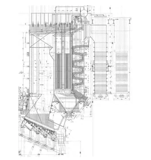
The boiler layout is shown in Figure 1.
Coupe Longitudinale
Economiseur
Economiseur
Vaporisateur
Vaporisateur
Surchauffeur
Figure 1:
Line 2 boiler – Lagny
The boiler has a vertical arrangement with five gas passes: the first three are empty, the fourth one has vaporizer platens and the fifth one has a superheater, two vaporizers and two economizers.
163 Revamping Projects in the Waste-to-Energy Boilers in Brussels, Paris and Rome
Waste Incineration
Since its start up, the steam generator showed some difficulties in reaching the 300 °C design temperature in clean boiler conditions. The technicians stated that the tempe- rature was lower than 270 °C during the first three weeks of operation starting from clean boiler and lower than 280 °C in the subsequent eight weeks. The steam condition to enter the turbine were matched only after more than two months of operation.
In addition, since the boiler was equipped with only one superheater with no steam temperature control systems via intermediate attemperator, once the typical fouling of this kind of boiler was reached, the superheated steam at the output reached a tem- perature of 310 °C and more.
Unfortunately, once the desired temperature had been reached, the fouling phenomena were such that the boiler needed to be shut down for a complete sandblasting in order to make the plant ready to properly operate again.
As such, the operating ours of the turbine at designed temperature were really limited, even lower than 4,000 hours per year.
Failure to achieve the project temperature was mainly due to the very large vaporization surfaces, poor superheater sizing, absence of a temperature control system and limited efficiency of the cleaning system of the boiler.
1.2. Bruxelles Energie – Brussels (Belgium)
The three Bruxelles Energie boilers are identical and designed to produce 51 t/h at 395 °C and 40 bar(g) from MSW combustion. The boilers were manufactured by CNIM and commissioned in 1985. Their original configuration is shown in Figure 2.
The boilers have vertical arrangement with four gas passes: the first two are empty, the third one has a vaporizer and a high, medium and low temperature superheater, while the fourth one has only economizers.
The boilers immediately showed corrosion problems mainly in two areas: in the fins of the membrane walls of the first and second radiant passes and in the superheaters.
The first phenomenon, due to a too large fin, was initially solved by the client, by app- lying refractory material in areas affected by the phenomenon, while the replacement of the original walls with Inconel 625 coated surfaces is currently underway.
Regarding the superheater corrosion, the phenomenon was so damaging that the life of the first superheater was less than one year and the life of the second one was less than two years. These corrosion problems were solved by removing the first two superheaters and replacing them with independent gas-fired superheater, outside the boiler. As a consequence, the plant reduced extraordinary shut downs but suffered a significant increase in management costs due to natural gas consumption of the external burners.
Figure 3 shows the boiler configuration, before our intervention.
Agostino Calcagno, Joao Parente, Luigi Bagnoli
164
Waste Incineration Figure 3: Bruxelles Energie boiler after superheater removalFigure 2: Original Bruxelles Energie boiler
IRF.pdf 1 11.08.16 10:07
Dorfstraße 51
D-16816 Nietwerder-Neuruppin
Tel. +49.3391-45.45-0 • Fax +49.3391-45.45-10 E-Mail: tkverlag@vivis.de
Order now: www. .de
TK Verlag Karl Thomé-Kozmiensky
260.00 EUR
save 90.00 EUR Aschen • Schlacken • Stäube
Mineralische Nebenprodukte und Abfälle,Volume 1 – 3
Package Price
Editor: Karl J. Thomé-Kozmiensky • Publisher: TK Verlag Karl Thomé-Kozmiensky
Mineralische Nebenprodukte und Abfälle
– Aschen, Schlacken, Stäube und Baurestmassen – 2014 (ISBN: 978-3-944310-11-4) Price: 50.00 EUR Mineralische Nebenprodukte und Abfälle 2
– Aschen, Schlacken, Stäube und Baurestmassen – 2015 (ISBN: 978-3-944310-21-3) Price: 50.00 EUR Mineralische Nebenprodukte und Abfälle 3
– Aschen, Schlacken, Stäube und Baurestmassen – 2016 (ISBN: 978-3-944310-28-2) Price: 100.00 EUR Mineralische Nebenprodukte und Abfälle 4
– Aschen, Schlacken, Stäube und Baurestmassen – 2017 (ISBN: 978-3-944310-35-0) Price: 100.00 EUR Aschen • Schlacken • Stäube
– aus Abfallverbrennung und Metallurgie – 2013 (ISBN: 978-3-935317-99-3) Price: 50.00 EUR
Ash • Slag • Dust
Mineral By-Products and Waste
M M
M M
M M
M M M
M M
M
M M
M
M
3 Karl J. Thomé-Kozmiensky
MINERALISCHE NEBENPRODUKTE UND ABFÄLLE 2 – Aschen, Schlacken, Stäube und Baurestmassen –
Karl J. Thomé-KozmienskyMineralische Nebenprodukte und Abfälle
2
Thomé-Kozmiensky und VersteylAschen • Schlacken • StäubeThomé-Kozmiensky
Karl J. Thomé-Kozmiensky
Aschen • Schlacken • Stäube
– aus Abfallverbrennung und Metallurgie –
3 Karl J. Thomé-Kozmiensky
MINERALISCHE NEBENPRODUKTE UND ABFÄLLE 3 – Aschen, Schlacken, Stäube und Baurestmassen –
Karl J. Thomé-KozmienskyMineralische Nebenprodukte und Abfälle
3
3
Karl J. Thomé-KozmienskyMineralische Nebenprodukte und Abfälle
4
Karl J. Thomé-Kozmiensky
MINERALISCHE NEBENPRODUKTE UND ABFÄLLE 4
– Aschen, Schlacken, Stäube und Baurestmassen –
Mineralische_Nebenprodukte_Aschen-Schlacken-Stäube_Engl.pdf 2 30.08.17 13:58
167 Revamping Projects in the Waste-to-Energy Boilers in Brussels, Paris and Rome
Waste Incineration
With this configuration, the boiler produced 65 t/h at 320 °C and 40 bar (g). The steam was subsequently heated to 395 °C by an external gas-fired superheater before being injected into the turbine.
1.3. Hera – Pozzilli (Italy)
The plant of Pozzilli (IT), located about 150 km from Rome, owned by HERA SpA, is an RDF combustion plant, equipped with Martin grate and CNIM boiler. The plant started operating in 2007 and is currently used to produce 61 t/h of steam at 400 °C and 60 bar(g), supplied to a steam turbine for the production of electricity.
Figure 4 shows the boiler section.
Figure 4: Pozzilli boiler
Agostino Calcagno, Joao Parente, Luigi Bagnoli
168
Waste Incineration
The boiler has vertical arrangement and consists of five gas passes: the first one is empty, the second one has high and low temperature superheaters, the third one has a vaporizer and the fourth and fifth ones have economizers.
The boiler immediately showed significant superheater corrosion problems, due to high concentrations of chlorine compounds (typical in the RDF combustion products) and to an unfavourable thermal profile: the high temperature gas immediately faced with the superheater surfaces, with the highest tube skin temperatures. These phenomena shortened the superheater life to less than one year. As a consequence, it was decided to replace the superheaters with Inconel 625 coated surfaces, but, despite this change, the superheater life did not show significant improvement: their life span was about two years.
2. Smart thermodynamic solutions to solve frequent problems
Higher fouling than expected and significant corrosion phenomena are the main pro- blems found in this type of plants. These phenomena lead to unexpected unavailability of the plant with long shut downs, which turn into extraordinary maintenance costs and loss of profits since the plants cannot be operated.
The typical approach of the managers to solve the fouling problems is often to install additional cleaning systems, such as soot blowers, bombing or rapping systems, that are very aggressive, are not always successful and can cause other sort of problems.
Regarding corrosion problems, it is usually necessary to replace the concerned parts with others coated with Inconel 625, with considerable financial investment.
Our approach is to make a new and complete boiler calculation in order to design a new heat profile focused on the reduction of the gas temperatures facing each thermal unit. This will lead to reduce molten ashes deposits, and to dramatically reduce the corrosion phenomena.
3. Modifications made to the plants
After having carefully examined the specifications required by plant managers and the operating data, significant changes to each plant were agreed upon.
3.1. Suez – Lagny (France)
The works for the modifications took place in August 2016 and plant commissioning occurred in September of the same year. The solution adopted to solve the problems concerning the failure to achieve the superheated steam temperature was to insert a superheater into the third flue gas pass, operating as a high temperature superheater.
In addition to the aforementioned superheater, a desuperheating valve was inserted into the pipe connecting the two superheaters in order to actively control the steam temperature at the exit. Figure 5 shows a drawing of the modified boiler.
169 Revamping Projects in the Waste-to-Energy Boilers in Brussels, Paris and Rome
Waste Incineration
Figure 5:
Line 2 boiler located in Lagny after revamping
New Superheater
This thermodynamic solution was simple, but it was a bit more difficult to apply it to the existing boiler. Particularly the client was looking for the best solution for the cleaning system of the new superheater.
The new superheater was designed with a very large transversal and longitudinal tube pitches, in order to allow an easy passage of the combustion gases, reduce pressure drops and prevent the possibility of clogging due to ashes. The superheater has been equipped with a hammer cleaning system, placed at the top, outside the flue gas pass with our patented solution. Upon customer specific request, the superheater was provided with a 2 mm Inconel 625 coating to further protect the superheater from the instability of the furnace and ensure a very long life.
The superheater was inserted from the top of radiant no. 3 through an opening made on the ceiling, as large as the boiler. This required the repositioning of the water-steam mixture risers and an in-depth study of the circulation.
Agostino Calcagno, Joao Parente, Luigi Bagnoli
170
Waste Incineration
As a result of intervention, the plant is able to reach the requested superheater tempe- rature of 320 °C from the very beginning and maximize the production of electricity.
Moreover, after eight months of operation, the fouling of the superheater is according to our design and no stop for extraordinary cleaning of the superheater is needed.
3.2. Bruxelles Energie – Brussels (Belgium)
The changes made to the Bruxelles Energie plant concerned two of the three existing boilers with interventions in 2014 and 2015.
The goal was to produce superheated steam in the boiler at 350 °C, so as to reduce the external superheating and consequently reduce plant management costs, with the mandatory focus on not causing new superheater corrosion. Figure 6 shows the interventions on the boilers.
New Vaporizer New Superheater
Figure 6:
Bruxelles Energie boiler after revamping
The interventions focused on the third flue gas pass, where the vaporizer surface was enlarged and a new superheater was inserted.
171 Revamping Projects in the Waste-to-Energy Boilers in Brussels, Paris and Rome
Waste Incineration
The increase in the vaporizer surface allowed the reduction of gas temperature at the superheater inlet, thus controlling the corrosion phenomenon. Downstream of the new vaporizing surfaces, a co-current low temperature superheater was installed so that the higher-temperature gas could come into contact with the surfaces crossed by the steam at a lower temperature, always to keep the corrosion under control. The existing superheater became a high temperature superheater, always placed in co-current with respect to gas directions. In the piping connection between the two superheaters, an attemperator was installed to allow temperature control. Special attention was paid to minimize steam pressure drops, in order to not affect the safety valves placed on the steam drum. All the soot-blowers of the concerned areas has been repositioned.
The modified boiler showed immediately that the outgoing steam could reach the re- quested temperature of 350 °C. As after one year of operation no thickness reduction was found due to corrosion. The same intervention has been completed on line 2 with same positive results.
Given the excellent results achieved on lines 1 and 2, an intervention on line 3 is plan- ned with a higher goal: allow a superheated steam temperature of 385 °C at the exit of the high temperature superheater in order to completely remove the external gas-fired superheater resulting in huge savings on management costs.
3.3. Hera – Pozzilli (Italy)
Among the three aforementioned interventions, the one made in the Pozzilli plant is undoubtedly the most complex. The intervention was aimed at modifying the vertical arrangement of convective pass of the existing boiler into a horizontal one.
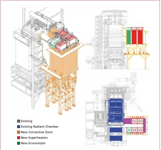
The change, under construction, will be completed in November 2017 and the boiler commissioning is scheduled for December 2017. The modifications performed on the boiler are shown in Figure 7.
As it can be seen, the superheaters and the vaporizer will be removed from the second and the third flue gas passes, so as to create three radiant flue gas pass completely emp- ty. This will allow the temperature to be lowered before entering the convective pass and the gas to be de-dusted.
In the upper area of the third flue gas pass, the existing opening to access the economi- zer area will be closed and a rectangular section opening will be carried out laterally.
From it, the gas will pass through a new fourth empty channel realized with membrane walls, equipped with a flow diverter wall, and will flow into the new convective area, where four new superheaters and a new economizer will be installed. Downstream the new economizer, the gas will be conveyed again in the area of the existing economizers through a duct via a new lateral opening. The plan view shows the new horseshoe- shaped convective zone. This new superheater arrangement allows the boiler thermal profile to be improved, while ensuring that the gas enter the convective zone at lower temperatures, drastically reducing the corrosion phenomena. In addition, the cleaning system used for the new components is our patented hammers cleaning system.
Agostino Calcagno, Joao Parente, Luigi Bagnoli
172
Waste Incineration
Special attention was paid to the fluid dynamics study of the gas, in order to ensure the correct distribution in new thermal units. In addition, it was also necessary to minimize gas-side pressure drops as the technical specification required very low guaranteed values due to the fact that replacement of the existing extraction fan was not planned.
This type of approach is totally revolutionary for the major revamping cases concerning the existing boilers, as it extends the possibility for all vertical boilers to be turned into horizontal boilers with the known advantages that this implies: less fouling and boilers less subjected to corrosion. This means lower maintenance costs and greater annual plant availability.
4. Ruths boiler for the combustion of MSW and RDF
Thanks to our years of experience in the field of MSW and RDF combustion, both for new plants and for major revamping of existing boilers, our company developed
Existing
Existing Radiant Chamber New Convective Zone New Superheaters New Economizer
Figure 7: Pozzili boiler after revamping
173 Revamping Projects in the Waste-to-Energy Boilers in Brussels, Paris and Rome
Waste Incineration
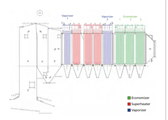
a project that ensures excellent reliability, minimizes management costs and guarantees a high annual availability without loss in performance due to progressive clogging and corrosion. A typical example of a project of our boilers is shown in Figure 8, related to the San Vittore del Lazio (Italy) plant, located a few kilometres from Rome. It is RDF-fired boiler that produces 60 t/h of steam at 420 °C and 43 bars, commissioned in October 2016.
Economizer Superheater Vaporizer Vaporizer
1 Vaporizer
2 Economizer
1 2 3
Figure 8: RDF combustion boiler in San Vittore del Lazio
The main features that allow high reliability to our boilers are:
• Three wide radiant channels: they allow the gas to be cooled down at the entry of the convective pass and thanks to their low speeds greatly help in de-dusting.
• Horizontal boilers: this type of arrangement improves the de-dusting capabilities of the boiler.
• Particular attention to the thermal profile: a good management of the boiler thermal profile naturally reduces corrosion and clogging phenomena, and consequently the number of shut down for extraordinary maintenance.
• External hammer cleaning system, positioned on the top: unlike soot blowers, which are very aggressive or hammer cleaning systems acting on the lower ma- nifolds of the thermal units, our system ensures a good cleaning degree, without increasing the risk of corrosion or mechanical breakage.
Agostino Calcagno, Joao Parente, Luigi Bagnoli
174
Waste Incineration
• Very easy thermal unit replacement: all superheaters, economisers and even va- porizers, can be replaced without any welding activity because they have flanged connections and they leave our workshop already provided with the Notified Body certification. Therefore, the replacement time of any thermal unit is reduced to less than eight hours.
Dorfstraße 51 D-16816 Nietwerder-Neuruppin Tel. +49.3391-45.45-0 • Fax +49.3391-45.45-10 E-Mail: tkverlag@vivis.de
Order now: www. .de
TK Verlag Karl Thomé-Kozmiensky
Air Pollutant Emissions and their Control
– with the focus on waste incineration facilities –
This comprehensive text and practical handbook thoroughly presents the control of air pollutant emissions from combustion processes focusing on waste incinerators. Special characteristics are emphasised and the differences to emission control from combustion processes with other fuels are explained.
The author illustrates the origin and effects of air pollutants from incineration processes, the mechanics of their appearance in the incineration process, primary and secondary measures for their reduction, processes of measuring the emissions as well as the methods of disposing the residues. In particular, the pros and cons of procedual steps and their appropriate combination under various conditions are emphasised.
Moreover, the book contains information and analyses of the emissions situation, the consumption of operating materials and of backlog quantities as well as of the cost structure of waste incinerators with regard to their applied control system.
Furthermore, the author explicates the contemporary legal, scientific and technological developments and their influence on air pollutant emission control. An evaluation of the status quo of air pollutant control at waste incinerators in Germany, practical examples about possible combinations and typical performance data complete the content.
Accordingly, this book is a guideline for planing a reasonable overall concept of an air pollutant control that takes the location and the segregation tasks into consideration. This book is addressed to students, decision makers, planners and the operating practicioners if for example the construction of a new system or the implementation of improvement measures have to be conducted.
Emissions and Emission Monitoring
340 Fixed mirror
Focussing mirror Beam splitter
with compensator
Moving mirror
Light source Gas sample Gas sample Collimator
Detector Sample cell
Figure 242: Measurement principle of an FTIR multi-component spectrometer with a Michelson interferometer setup
Source:
TÜV Süd Industrie Service GmbH, UBA-Texte 05/08, adapted
splitter where they are brought together to interfere with each another in intensity as they recombine. Depending on the mirror displacement, the interference may be constructive (increasing) or destructive (decreasing). When using polychromatic light, the interference occurs for each wave length so that the interference intensities of the individual wave lengths superpose one another [369].
of the target component and are directed by a focusing mirror to an infrared detector is computed from the recorded interferogram (intensity at detector as a function of mirror displacement) by mathematical Fourier transformation. For quantitative eva- luation, the calculated infrared spectrum is compared with a reference spectrum [380].
An alternative to the Michelson interferometer is the vibration-insensitive RockSolid arrangement [356].
341 9.2.3.3.2 Multi-component measurement by non-dispersive infrared spectroscopy Non-dispersive infrared (NDIR) spectroscopy is based on the absorption of an in- frared spectrum wavelength that is unique to the gaseous component to be detected.
In contrast with dispersive infrared spectroscopy, non-dispersive methods do not spectroscopy is applicable to multi-component analysis, i.e. the simultaneous analysis of several emission parameters, and is frequently also used for raw gas measurements.
detector
Light source Sample cell Calibration filter Lens
Detector
Filter wheels Chopper
Figure 243: Measurement principle of a multi-component NDIR spectrometer with heated sample gas cell Source: Boneß, M.: Messsysteme und Analysatoren zur kontinuierlichen Prozesskontrolle und Emissionsüberwachung in und Betrieb von Anlagen, Vol. 1, pp. 527–538. Neuruppin: TK Verlag, 2010 As infrared detectors can only detect changes in the infrared radiation, they require a modulated (pulsed) infrared source that is temporarily interrupted by a mechanical
component and selects the spectral region of its absorption band. If several gas com- ponents are to be analysed, chopper wheels covering several infrared spectral regions to calculate the gas concentration, which requires a concentration-independent refer- ence signal for comparison. For this purpose, NDIR analysers may be equipped with absorption band of the analysed component (bi-frequency technique). Alternatively,
.
Continuous Emission Monitoring
Released: August 2017 120.00 EUR
Also available in German!
50.00 EUR
Vorwort
4
Bibliografische Information der Deutschen Nationalbibliothek Die Deutsche Nationalbibliothek verzeichnet diese Publikation in der Deutschen Nationalbibliografie; detaillierte bibliografische Daten sind im Internet über http://dnb.dnb.de abrufbar
Thomé-Kozmiensky, K. J.; Thiel, S.; Thomé-Kozmiensky, E.;
Winter, F.; Juchelková, D. (Eds.): Waste Management, Volume 7 – Waste-to-Energy – ISBN 978-3-944310-37-4 TK Verlag Karl Thomé-Kozmiensky
Copyright: Elisabeth Thomé-Kozmiensky, M.Sc., Dr.-Ing. Stephanie Thiel All rights reserved
Publisher: TK Verlag Karl Thomé-Kozmiensky • Neuruppin 2017
Editorial office: Dr.-Ing. Stephanie Thiel, Elisabeth Thomé-Kozmiensky, M. Sc.
Janin Burbott-Seidel and Claudia Naumann-Deppe
Layout: Sandra Peters, Anne Kuhlo, Ginette Teske, Claudia Naumann-Deppe, Janin Burbott-Seidel, Gabi Spiegel and Cordula Müller
Printing: Universal Medien GmbH, Munich
This work is protected by copyright. The rights founded by this, particularly those of translation, reprinting, lecturing, extraction of illustrations and tables, broadcasting, micro- filming or reproduction by other means and storing in a retrieval system, remain reserved, even for exploitation only of excerpts. Reproduction of this work or of part of this work, also in individual cases, is only permissible within the limits of the legal provisions of the copyright law of the Federal Republic of Germany from 9 September 1965 in the currently valid revision. There is a fundamental duty to pay for this. Infringements are subject to the penal provisions of the copyright law.
The repeating of commonly used names, trade names, goods descriptions etc. in this work does not permit, even without specific mention, the assumption that such names are to be considered free under the terms of the law concerning goods descriptions and trade mark protection and can thus be used by anyone.
Should reference be made in this work, directly or indirectly, to laws, regulations or guide- lines, e.g. DIN, VDI, VDE, VGB, or these are quoted from, then the publisher cannot ac- cept any guarantee for correctness, completeness or currency. It is recommended to refer to the complete regulations or guidelines in their currently valid versions if required for ones own work.