www.CheMin.de
Understanding and Improving
Thermochemical Processes
501 The Corrosion Mechanisms in Waste-to-Energy Plants
Materials and Corrosion
Get to Know the Corrosion Mechanisms in Waste-to-Energy Plants
Gabriele Magel
1. Introduction ...502
2. Mechanisms of corrosion ...502
2.1. High temperature corrosion ...503
2.2. Salt melt corrosion (hot corrosion) ...504
2.3. Deliquescence corrosion ...504
2.4. Dew point corrosion ...505
3. Investigation of the corrosion mechanism ...505
4. Case studies ...509
4.1. Case study 1: Corrosion mechanisms in a superheater ...509
4.2. Case study 2: Corrosion behaviour of different materials at a superheater ...510
4.3. Case study 3: Corrosive behaviour due to lowering of the flue gas temperature at the cold end of a boiler ...511
5. Conclusions ...512
6. References ...513 The availability of waste-to-energy power plants is often highly limited because of ma- terial wear. Due to complex interactions between operating conditions, composition of fuels and flue gas as well as temperature conditions in the heat recovery steam generator (HRSG), especially power plants with difficult fuel such as waste, waste derived fuels and waste wood have to face big challenges to reach high efficiency. In most cases, chlorine species combined with heavy metals are known to cause fireside corrosion in HRSG in waste-to-energy technologies.
Depending on the interactions mentioned above, different fireside corrosion mecha- nisms occur:
• high temperature corrosion,
• salt melt corrosion,
www.CheMin.de
Understanding and Improving
Thermochemical Processes
Gabriele Magel
502
Materials and Corrosion
• dew point corrosion,
• deliquescence corrosion.
The examinations of the deposits that were formed on the surface of the different components and with which the corrosive attack can be studied, can only be carried out during outages. To get important information in a shorter period of time, probes are a useful tool to describe and understand the different corrosion mechanisms online in an actual boiler situation.
CheMin developed temperature range probes to analyse the causes, mechanisms and dynamics of corrosion. In numerous applications, temperature thresholds for corrosion processes and/or the corrosion mechanisms were examined. The probes can be used at high temperatures (combustion chamber to superheater) as well as at low temperatures (economizer and flue gas cleaning) and can help to get a quick and significant decision for the given corrosive situation.
1. Introduction
High energy efficiency and availability is one of the main targets for managers and operators of power plants. However, this often collides with the real situation in a waste-to-energy plant, where a corrosive attack of metallic materials may play a do- minant role. The corrosion processes are strongly connected to the properties of the fuel and the firing conditions. Unfavorable properties of fuel and firing can mutually reinforce one another. Therefore, especially boilers with difficult fuels (like waste, re- fuse derived fuels, waste wood) that often contain a higher load of chlorine and heavy metal species, frequently suffer strong corrosion. Having these species in the flue gas, fireside corrosion is likely to occur at different places and components in the boiler, starting with the high-temperature corrosion at superheaters and evaporators, followed by low temperature corrosion on economizers as well as on components of the flue gas cleaning.
Due to different parameters (firing conditions, different temperature conditions, geometry of the boiler and others) the transferability of knowledge and findings on mechanisms and solutions from one plant to another is limited [1, 2].
In this paper, a closer view to different corrosion processes is offered, and various case studies of boilers with corrosion problems together with potential solutions are shown.
2. Mechanisms of corrosion
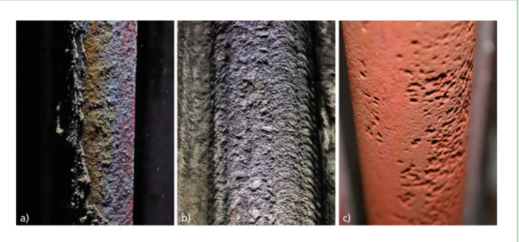
In waste-to-energy plants, different kinds of corrosive behaviour can be observed (Figure 1). What kind of corrosion mechanism occurs depends on the chemistry within the flue gas, the installed material as well as the temperature conditions in the boiler.
In the following section, the main corrosion phenomena are introduced.
503 The Corrosion Mechanisms in Waste-to-Energy Plants
Materials and Corrosion
Figure 1: Tube surfaces with different corrosion mechanisms: a) high temperature corrosion on a superheater tube; b) salt melt corrosion on a tube cladding (alloy 625) in the 1st pass;
c) deliquescence corrosion on an economizer tube
2.1. High temperature corrosion
The chain of mechanisms and reactions of high temperature corrosion is complex.
It is mainly caused by chlorine species.
The chain of high temperature corrosion already begins at startup of the boiler: the chlorine species that are released from the fuel during combustion are dissolved in the flue gas. At the relatively cold heat exchanger surfaces (cold trap), the saturated chlorine salts condense and can directly cause corrosion on metallic surfaces.
The amount of the chlorides near the steel surface, which is a major contributor to corrosion, is controlled on the one hand by the load of chlorides in the flue gas and on the other hand by the heat flux. At positions with high heat flux, the partial pressure of the chlorine salts near the steel surface is elevated, which means a high reactivity of the chlorides is given.
On the steel surface, the reaction between the chlorides and the iron leads to iron chloride, even at low chlorine concentrations within the flue gas [2]. The partial pres- sure of iron chloride gas is high at the steel surface. Consequently, it diffuses into the fouling where it comes in contact with oxygen to form iron oxide (Fe2O3 mostly, but also Fe3O4). This is the reason why chlorine corrosion is called active oxidation [5].
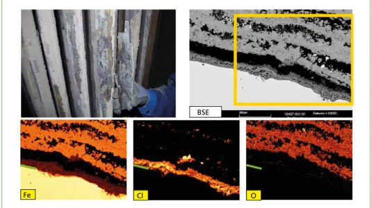
Chlorine is released and diffuses back to the steel (concentration balance) to cause a further corrosive attack. The result is an iron chloride layer directly on the tube surface, followed by a thicker layer of iron oxides, often penetrated by chloride salts (Figure 2).
This indicates that for the intensity of the high temperature corrosion, the content of chlorine species in the fuel or in the flue gas are not as important as the content of specific chlorides inside the fouling as well as the heat flux density at the tube wall.
a) b) c)
Gabriele Magel
504
Materials and Corrosion
Figure 2: High temperature chlorine corrosion on a superheater tube. With the scanning electron microscope, the structure of the fouling can be studied: directly on the tube surface, a layer of iron chloride is formed followed by iron oxides. In the element mapping, the distribution of the different elements can be seen (yellow: high amount; black low amount;
the green line marks the steel surface).
2.2. Salt melt corrosion (hot corrosion)
The process of salt melt corrosion starts basically similar to the high temperature corrosion. However, the temperature conditions on the tube surface must be relatively high compared to the melting point of the precipitated salts, so that salt melts exist directly on the metal surface.
There are different processes known that may arise from the salt melts: On the one hand, the melts may dissolve existing oxide layers [4], which allow the corrosive chlorine gas to move towards the metal surface. On the other hand, salt melts may change the structure of the fouling from a porous to a dense cover. This means the iron chloride is trapped and closed off from the gaseous oxygen. In this way, a special micro milieu is formed under the deposits that support chlorine corrosion [9]. A further mechanism is possible when the salt melts react as a liquid electrolyte directly with the steel, forming single pits. While dissolving the metal, the elements of the steel become part of the salt melt. As a consequence, the melting temperature increases, causing the melt to freeze.
In most cases, the surface of the metal is characterised by corrosion pits (Figure 1).
2.3. Deliquescence corrosion
This type of corrosion starts basically similar to the high temperature corrosion with the precipitation of saturated salts on the tube surfaces, but it affects the salts at low temperatures only. Special salts absorb water from the surroundings under certain
BSE
Fe Cl O
505 The Corrosion Mechanisms in Waste-to-Energy Plants
Materials and Corrosion
conditions. The deliquescence temperature of these salts is significantly higher than the water dew point. At this temperature the solid salts change to form a liquid solution, which is why these salts are called deliquescent salts.
During plant operation, these specific salts
• are deposited by desublimation (transition from gas phase to solids) and
• absorb moisture to liquefy.
A good example for these kinds of salts are ammonium salts which are transported as gaseous species in the flue gas until relatively low temperatures are reached. At the cold end of the boiler, these salts can be the dominating species to precipitate and build up the fouling. Other examples are CaCl2, ZnCl2 and mixtures of these salts.
The liquefied deliquescent salts can form chlorine-containing electrolytes at flue gas temperatures below about 140 °C on corresponding boiler components, such as the economizer and components of the flue gas cleaning as well as the clean gas side. Details concerning fuels, firing conditions and plant operation are described by Herzog et al.
[3] and Montgomery et al. [6].
2.4. Dew point corrosion
When a specific gaseous species reaches saturation in a flue gas with decreasing tem- perature, droplets of the liquid condense on solid surfaces. The saturation temperature depends on the load of the concerned species and in case of sulfuric acid also on the humidity of the flue gas. The liquid electrolyte can form wet spots on the surfaces, causing general corrosion and an almost even material loss. Other examples show droplets causing local pits.
The term dew point corrosion is mainly used for sulfuric acid and it occurs, e.g., in coal fired power plants. In waste-to-energy plants the dew point corrosion is not common, as SO3, which is the starting phase for the formation of sulfuric acid, reacts with chlorine species, and so the formation of sulfuric acid is unlikely.
3. Investigation of the corrosion mechanism
The different corrosion mechanisms that can be observed on the metallic surfaces in a HRSG, are already known in general. However, the corrosion mechanisms are only the final link at the end of a chain of mechanisms and reactions of the complex interactions between operating conditions, composition of fuel and flue gas as well as temperature conditions in the HRSG.
To find a feasible approach for optimisation of the process, it is necessary to study the chain of interactions between these parameters [1]. Useful tools for this approach are the temperature range probes with which the plant performance such as boiler effici- ency, component lifetime or availability can be improved.
Gabriele Magel
506
Materials and Corrosion
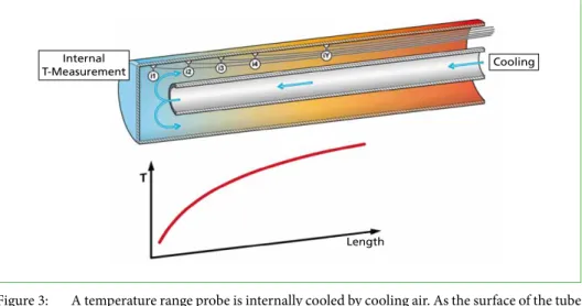
When applying a temperature range probe to the flue gas, the surface of the probe is imitating the tube surfaces of the component that has to be studied. The temperature range probe consists of an outer tube (probe tube) and an internal tube that is used for cooling with compressed air (Figure 3). The probe tube is therefore cooled from the inside and is heated by the flue gas from the outside. The internal tube ends at the front part of the probe tube. This is where the cooling air enters the probe tube, causing the front section of it to be the best cooled part of the probe. Towards the rear of the probe, the surface is heated gradually. Therefore, a temperature profile is developed on the tube surface that rises towards the end of the probe. With internal temperature measurements, that are coupled to an electronic control, the temperature window on the tube surface can be kept constant at a specific level.
The design of the probe (length, diameter, material, etc.) can be adjusted and the re- quired temperature window can be adapted to the particular situation or problem that has to be investigated. The temperature range probes can be installed at conditions with the flue gas temperatures between 1,200 °C and 100 °C.
Internal
T-Measurement Cooling
Length
Figure 3: A temperature range probe is internally cooled by cooling air. As the surface of the tube is heated by the flue gas, the surface temperature of the probe rises from the front part towards the rear of the probe.
With these themperature range probes, useful information can be gathered that can help to improve the availability of the plants. This can be, for example, information on
• cause, mechanism and dynamics of corrosion,
• cause and composition of fouling,
• impact of a special kind of fuel on the corrosion and/or fouling,
• impact of the way of operation on the corrosion and/or fouling,
• temperature threshold for corrosion, and
• most suitable materials.
Dorfstraße 51 D-16816 Nietwerder-Neuruppin Tel. +49.3391-45.45-0 • Fax +49.3391-45.45-10 E-Mail: tkverlag@vivis.de
Order now: www. .de
TK Verlag Karl Thomé-Kozmiensky
Waste-to-Energy Plants
– Germany –
This book carries forward the survey of waste-to-energy plants in the Federal Republic of Germany which started in the 1990´s. This edition comprises:
• 52 plants that treat municipal solid waste.
• 1 plant that treats hazardous waste.
The investigation provides extensive information about the installed technology and the environmental impact of the waste-to-energy plants. The quality of the inquiry has been extended in terms of the technical data.
Existing gaps regarding the data were partially filled, as a comparison with the survey of 1994 reveals. This is the result from the considerable assistance of numerous plant operators. The publication on hand shall be seen as an interims report. The work on the data acquisition will be continued. For this reason we ask plant operators and manufactures to critically review the release data.
The further investigations will be extended to the missing German waste-to-energy plants as well as to plants in other countries.
Elisabeth Thomé-Kozmiensky
112 1.5. Generalunternehmer
(Planung und Ausführung) Deutsche Babcock Anlagen GmbH
Kesselerneuerung Von Roll Inova, resp. HITACHI Zosen Inova Turbinenerneuerung
1.6. Genehmigungsbehörde Regierung von Oberfranken Ludwigstraße 20 95444 Bayreuth
1.7. Aufsichtsführende Behörde Bayerisches Landesamt für Umweltschutz Bürgermeister Ullrich-Straße 160 86179 Augsburg 1.8. Inbetriebnahme 1978: KlärschlammbehandlungLinien 1 + 2 und
1981: Linie 3
1982: Erweiterung um Stromerzeugung 1982-1988: Fernwärmeauskopplung und -verteilung 1990: Feuerraumoptimierung, 1. Erweiterung der Abgasreinigungsanlage
1996: 2. Erweiterung der
Abgasreinigungsanlage
Bild 3:
Abwasserbehandlung und Schlammentwässerung
Löschwasserbecken Notstrom- aggregate 3+4 Katalysatoren(SCR)
Gewebefilter Öl-tank
Waage Zentral- lager Grundstücksgrenze
Ausdehnungs- gefäß
Energieteil Abwärmenutzung Heizwerk 1 Abfall- bunker lieferungAn- Klärschlamm- Stapelbehälter
Kessel-hausElektro-filter
Teich Luftkondensator Maschinenhaus für
neue Turbine/Generator Wertstoffhof
Stadt Bamberg
Kompostieranlage Kläranlagengelände
AVA Augsburg
103 3. Abfallaufkommen
Abfallarten
Hausmüll: 131.103 t
hausmüllähnlicher Gewerbemüll: 81.835 t
Sperrmüll: 14.204 t
Krankenhausabfälle: 3.363 t
insgesamt: 230.505 t
4. Kapazität, Durchsatz und Geometrie Kapazität (Auslegung) 255.000 t/a davon
• Siedlungsabfälle: 251.500 t/a
• Krankenhausabfälle: 3.500 t/a bei einem Heizwert von 9,2 MJ/kg Durchsatz (Siedlungsabfälle)
Durchsatz 2014: 238.224 t
Durchsatz 2013: 236.693 t
Durchsatz 2012: 233.888 t
Durchsatz (Krankenhausabfälle)
Durchsatz 2014: 3.363 t
Durchsatz 2013: 3.097 t
Durchsatz 2012: 3.257 t
Abmessungen des Baukörpers 235.000 m2
Bauhöhe ohne Kamin: 38 m
5. Anlieferung und Lagerung Abfallanlieferungen mit: LKW
~ 35.000 Anlieferungen/Jahr 5.1. Waage Hersteller:
Bauart: Brückenwaage
Anzahl: 3
5.2. Anlieferungshalle/Entladestation Anzahl der Abkippstellen: 12 5.3. Bunker für feste Abfälle Abfallart: Siedlungsabfälle Maße (l x b x h) 55 m x 13 m x 25 m nutzbares Volumen: 10.000 m3
Nutzmasse: ~ 5.000 t
Anzahl der Abkippstellen: 12 Abfallart: Krankenhausabfälle nutzbares Volumen: 5.000 m3 5.4. Bunker für Schlacken nutzbares Volumen: ~ 500 m3
5.5. Betriebsmittellagerung
Heizöl: ~ 80 m3
Ammoniakwasser: ~ 60 m3
Kalksilo: ~ 50 m3
Natronlauge: ~ 50 m3
Bild 4: Müllfahrzeuge beim Abkippen von Abfall in Müllbunker Bild 5: Schlackehalle der AVA Augsburg
ABFALLVERBRENNUNGSANLAGEN – Deutschland – 2014 | 2015
Editor: Elisabeth Thomé-Kozmiensky Released: 2016
ISBN: 978-3-944310-26-8 Hardcover: 581 pages Price: 68.00 EUR Language: German
ABFALLVERBRENNUNGSANLAGEN – Deutschland –
2014 | 2015 Elisabeth Thomé-Kozmiensky Anlagendoku_engl.pdf 1 03.07.17 13:54
Pressure Parts for Professionals
Steam Generators from 30 t / h to 3.000 t / h
Burners for Coal, Gas, Oil, Biomass
Components:
Membrane Walls, Coils, Headers, Attemperators, Separators
www.mdkb.de
509 The Corrosion Mechanisms in Waste-to-Energy Plants
Materials and Corrosion
4. Case studies
On the following pages some case studies are described. In these cases temperature range probes were used to understand the corrosion processes in waste-to-energy boilers and to find possible solutions.
4.1. Case study 1: Corrosion mechanisms in a superheater
Situation The superheater in boilers with difficult fuel is often the main place of corrosive attack.
This is why the lifetime of this component often lasts for only a few years in the heavily affected areas. To optimise the lifetime of a superheater, the operator of a waste-to-ener- gy plant plans to replace the carbon steel tubes with cladded tubes (alloy 625). Before implementing the modification, CheMin had to compare the corrosion rate of the alloy 625 with the carbon steel under the given conditions to see if the investment will pay off.
In a second investigation, both materials should be compared again, but while burning a different fuel with a higher load of pollutants.
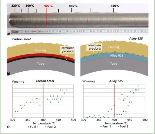
Investigation Temperature range probes were applied using the two different materials (carbon steel and alloy 625). The temperature window of the probe surface was kept at a constant level between 320 °C and 480 °C during the test. After an exposure time of about four weeks, the tube surface and the formed fouling at a surface temperature of 400 °C was studied. The application of the temperature range probe and the same investigation was repeated with a different kind of fuel to compare both situations and both materials.
Finding With the applied tests, it could be shown that different corrosion mechanisms occurred at both materials (Figure 4). On the carbon steel, the complete surface corroded in both fuel tests, causing two corrosion layers to appear, consisting of mainly Fe3O4 (black layer) and Fe2O3 (red layer). The probes therefore show clear indications for high temperature corrosion on the carbon steel. On the other hand, the alloy 625 is corroding with the formation of single corrosion pits; the surface between the corrosion pits is only slightly worn. This indicates that the surface of alloy 625 is attacked by salt melt corrosion under the given conditions.
The wearing rates at the superheater temperature of 400 °C could be shown for both materials.
At both tests, with the combustion of fuel 1, the wearing rate is distinctly lower than with the combustion of fuel 2. With the wearing rate of both materials and both situations, the calculation can be made, whether the investment is beneficial.
Pressure Parts for Professionals
Steam Generators from 30 t / h to 3.000 t / h
Burners for Coal, Gas, Oil, Biomass
Components:
Membrane Walls, Coils, Headers, Attemperators, Separators
www.mdkb.de
Gabriele Magel
510
Materials and Corrosion
Figure 4: a) Temperature range probes were used to investigate the corrosion mechanisms on superheater tubes (400 °C); b) Schematic illustration of the formed fouling on carbon steel and alloy 625; both materials show corrosion mechanisms which are essentially different; c) The diagrams show the wearing rates of the two materials in relation to the tube temperature for both kinds of fuels
4.2. Case study 2: Corrosion behaviour of different materials at a superheater
Situation
The superheater in a particular waste-to-enery boiler is exposed to high flue gas tem- peratures, and as a result the corrosion of the tube material is extremely high, so that the tubes in the most affected areas have to be replaced every year. This unsatisfactory situation should be improved by testing different materials under the same temperature conditions.
Investigation
Several materials are applied on different temperature range probes inserted into the flue gas at the position of the superheater. With these applications, the corrosion behaviour of these materials were tested under the same conditions.
corrosion products Fouling
Tube
Fouling
Tube Alloy 625 corrosion
products
Carbon Steel Alloy 625
400°C 440°C 480°C
360°C 320°C
a)
b)
300 350 400 450 500
Wearing
Temperature °C Carbon Steel
Fuel 1 Fuel 2
300 350 400 450 500
Alloy 625
Temperature °C Wearing
Fuel 1 Fuel 2 c)
511 The Corrosion Mechanisms in Waste-to-Energy Plants
Materials and Corrosion
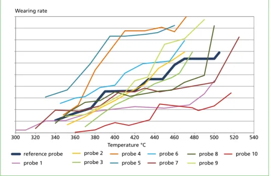
Finding The wearing rate of the currently installed material of the superheater tubes can be compared to the corrosion behaviour of various materials within a relatively short time period (Figure 5). When replacing the superheater, the most cost-effective material can be chosen.
300 320 340 360 380 400 420 440 460 480 500 520 540
Wearing rate
Temperature °C reference probe
probe 1
probe 2 probe 3
probe 4 probe 5
probe 6 probe 7
probe 8 probe 9
probe 10
Figure 5: With temperature range probes, the corrosion behaviour of different materials were tested under the same conditions.
4.3. Case study 3: Corrosive behaviour due to lowering of the flue gas temperature at the cold end of a boiler
Situation The managers of a waste-to-energy plant were looking for possibilities to rise the energy efficiency of the boiler. In this context, considerations were made whether the energy within the flue gas at the cold end of the boiler can be used without running the risk of corrosive attack on the installed materials.
Investigation A temperature range probe was applied at the stack. As there is no cooling of the installed material but a reasonable insulation installed at this component, the metal of the surrounding area is about the same temperature as the flue gas of about 140 °C. The temperature window of the probe surface was kept constant during the test between 70 °C and 120 °C.
Gabriele Magel
512
Materials and Corrosion
Finding
With the rising surface temperatures of the probe, the corrosion dynamics decrease (Figure 6). Below the temperature of about 90 °C, strong corrosion can be determined.
Lower corrosive attacks can be observed up to a temperature of 103 °C. To avoid cor- rosive attacks, all metal surfaces that are exposed to the flue gas should be kept above this temperature.
70 75 80 85 90 95 98 99 100 101 102 103 °C
Figure 6: A temperature range probe was applied at the cold end of the boiler to see the temperature threshold above which no corrosion occurs. In this case, indication for corrosion can be observed below 103 °C; under about 90 °C strong corrosion appears.
5. Conclusions
The findings of the corrosion mechanisms are based on long experience at CheMin, derived from damage analyses and expert reports for waste-to-energy plants.
Through-out many years of shutdown service and investigations, temperature range probes have been developed to examine the cause, dynamics and mechanisms of corrosion in different boiler components. With these tools the complex interactions between fuel, firing and temperature conditions can be studied in detail.
The framework conditions for operators of power plants are often fixed and the possible scope for improving the plant performance is highly limited. But there is almost always a possibility to somehow optimise the process.
To check the impact of different firing conditions or different fuels on corrosion, various operative situations can be created for a certain time period, where temperature range probes can be applied. In this way, the given possibilities for improving the process can be worked out.
513 The Corrosion Mechanisms in Waste-to-Energy Plants
Materials and Corrosion
As an example to increase the availability of a component, a possible solution could be to find a material that is more appropriate for the given conditions in terms of corrosion resistance. With the application of temperature range probes which imitate the surfaces of the boiler component, quick access to economical material solutions can be achieved.
A further example for the application of the temperature range probes shows how the boiler efficiency can be increased by lowering the flue gas temperature at the cold end of the boiler without running the risk of corrosive attack.
6. References
[1] Aleßio, H.-P.: Korrosion ohne Chemie? – Erläuterungen zum Hintergrund und zur Nutzung von Korrosionsdiagrammen. In: Thomé-Kozmiensky, K. J.; Beckmann, M. (Eds.): Energie aus Abfall, Band 11. Neuruppin: TK Verlag Karl Thomé-Kozmiensky, 2014, pp. 475-495
[2] Grabke, H.J.: Fundamental mechanisms of the attack of chlorine, HCl and chlorides on steels and high temperature alloys in the temperature range 400° to 900°C. In: Bryers, R.W. (Ed.):
Incinerating Municipal and Industrial Waste. Washington D.C.: Hemisphere Publishing Corp., 1991, pp. 161-177
[3] Herzog, T.; Spiegel, W.; Müller, W.; Brell, J.; Molitor, D.; Schneider, D.: Corrosion caused by Dew Point and Deliquescent Salts in the Boiler and the Flue Gas Cleaning. In: Thomé-Kozmiensky, K.
J.; Thiel, S. (Eds.): Waste Management, Vol. 3. Neuruppin: TK Verlag Karl Thomé-Kozmiensky, 2012, pp. 343-358
[4] Ishitsuka, T.; Nose, K.: Stability of protective oxide films in waste incineration environment – solubility measurement of oxides in molten chlorides. Corrosion Science, Vol. 44, 2, 2002 pp. 247-263
[5] McNallan, M. J.; Liang, W. W. et al.: Acceleration of the high temperature oxidation of metals by chlorine. In: Rapp, R.A. (Ed.): High Temperature Corrosion. Houston (TX): NACE International, 1983, pp. 316-321
[6] Montgomery, M.; Nielsen, L.V.; Petersen, M.B.: Utilization of on-line corrosion monitoring in the flue gas cleaning system. NACE Corrosion Concerence and Expo, paper no. 5550, 2015, p. 15
[7] Müller, W.; Kaiser, M.; Schneider, D.; Herzog, T.; Magel, G.; Spiegel, W.: Korrosion durch Alt- holzeinsatz in Biomassekraftwerken. In: Born, M. (Ed.): Dampferzeugerkorrosion 2013. Frei- berg: SAXONIA Standortentwicklungs- und Verwaltungsgesellschaft mbH, 2013, pp. 177-195;
available on www.chemin.de
[8] Müller, W.; Schneider, D.; Kaiser, M.; Brell, J.; Spiegel, W.; Pohl, M.: Fuel leaflets for the prevention of negative impact on the boiler from minor fuel constituents. VGB PowerTech, Vol. 7/2014.
2014, pp 76-81; available on www.chemin.de
[9] Spiegel, W.; Herzog, T.; Magel, G.; Müller, W.; Schmidl, W.: Dynamische chlorinduzierte Hoch- temperaturkorrosion von Verdampfer- und Überhitzerbauteilen aufgrund spezieller Belags- entwicklungen, häufiger Befund in Abfall- und Biomassegefeuerten Dampferzeugern. VGB PowerTech, Vol. 1-2, 2005, pp. 89-97; available on www.chemin.de
CNIM
35, rue de Bassano, 75008 Paris - France
Tel.: + 33 (0)1 44 31 11 00 - Fax: + 33 (0)1 44 31 11 30 E-mail: contact@cnim.com
www.cnim.com
Waste is a renewable energy source
> Turnkey design & build and services
> For:
• Household waste
• Commercial and industrial waste
• Biomass
• Fuels derived from waste
> To produce:
• Recyclable materials
• Compost
• Energy (heat and electricity)
Ardley Energy-from-Waste plant, Oxfordshire, UK
Courtesy of Viridor - © Julien Goldstein 08/2017 - Agence Huitième Jour
Vorwort
4
Bibliografische Information der Deutschen Nationalbibliothek Die Deutsche Nationalbibliothek verzeichnet diese Publikation in der Deutschen Nationalbibliografie; detaillierte bibliografische Daten sind im Internet über http://dnb.dnb.de abrufbar
Thomé-Kozmiensky, K. J.; Thiel, S.; Thomé-Kozmiensky, E.;
Winter, F.; Juchelková, D. (Eds.): Waste Management, Volume 7 – Waste-to-Energy – ISBN 978-3-944310-37-4 TK Verlag Karl Thomé-Kozmiensky
Copyright: Elisabeth Thomé-Kozmiensky, M.Sc., Dr.-Ing. Stephanie Thiel All rights reserved
Publisher: TK Verlag Karl Thomé-Kozmiensky • Neuruppin 2017
Editorial office: Dr.-Ing. Stephanie Thiel, Elisabeth Thomé-Kozmiensky, M. Sc.
Janin Burbott-Seidel and Claudia Naumann-Deppe
Layout: Sandra Peters, Anne Kuhlo, Ginette Teske, Claudia Naumann-Deppe, Janin Burbott-Seidel, Gabi Spiegel and Cordula Müller
Printing: Universal Medien GmbH, Munich
This work is protected by copyright. The rights founded by this, particularly those of translation, reprinting, lecturing, extraction of illustrations and tables, broadcasting, micro- filming or reproduction by other means and storing in a retrieval system, remain reserved, even for exploitation only of excerpts. Reproduction of this work or of part of this work, also in individual cases, is only permissible within the limits of the legal provisions of the copyright law of the Federal Republic of Germany from 9 September 1965 in the currently valid revision. There is a fundamental duty to pay for this. Infringements are subject to the penal provisions of the copyright law.
The repeating of commonly used names, trade names, goods descriptions etc. in this work does not permit, even without specific mention, the assumption that such names are to be considered free under the terms of the law concerning goods descriptions and trade mark protection and can thus be used by anyone.
Should reference be made in this work, directly or indirectly, to laws, regulations or guide- lines, e.g. DIN, VDI, VDE, VGB, or these are quoted from, then the publisher cannot ac- cept any guarantee for correctness, completeness or currency. It is recommended to refer to the complete regulations or guidelines in their currently valid versions if required for ones own work.