209 Balancing and Energy Efficiency of Waste Treatment Processes
Balancing and Energy Efficiency of Waste Treatment Processes
Michael Beckmann and Tobias Widder
1. Allocation of the term energy efficiency ...210
2. Necessity and properties of balance boundaries ...210
3. Mass, material and energy balances ...211
4. Specific values ...212
5. Preparation of equivalent values and energy exchange ratios ...212
6. Balance boundary module ...215
7. Balance boundary operation unit – paramount process subdivision – ..216
8. Balance boundary overall plant ...217
9. Balance boundary net overall plant ...217
10. Balance boundary to create the primary efficiency factor ...218
11. Balance boundary to create the net primary efficiency factor ...218
12. Exemplary Efficiency factors for a classical household waste incineration ...219
13. Energy quality in relation to production and consumption levels ...225
14. References ...227
Michael Beckmann, Tobias Widder
210
1. Allocation of the term energy efficiency
Energy efficiency is an effectiveness criterion for the evaluation of processes, plants and systems. It implies a statement about the used energy in relation to the input energy, but it cannot provide any information concerning the kind or quality of the input energy.
The effectiveness criteria can be quantified by means of specific values, and they crea- te the possibility to compare different technical units and systems at the same rank.
Prerequisite for the comparability is the conformity of balance boundaries and general requirements. Those input data that lead to the specific values come from a balance.
The balance itself and the resulting formation of specific values can be carried out for different time segments – e.g. momentary values, annual average.
2. Necessity and properties of balance boundaries
Before the energy in a waste-to-energy plant can be assessed, it is necessary to establish a balancing system with a balance boundary – balance circle – for the plant [2].
According to the definition the specific values for evaluating the energy efficiency are associated with the preparation of the mass, material and energy balances – see details in the corresponding chapters.
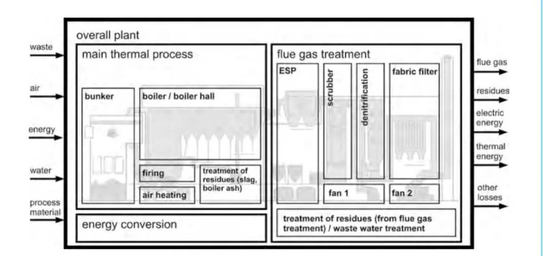
As usual in process engineering, implementing a model for mass, material and energy balances for an MSWI plant first requires that the boundaries are established for each unit operation (for aggregates, apparatuses, etc. [16]) in the MSWI plant process. Figure 1 shows a schematic of a typical MSWI plant with the main input streams being the waste, air, energy, water and operation material, and the main output streams being the flue gas, residues, energy for utilization and (heat) losses. Single unit operations can be combined to form the paramount balance units which in this paper will be termed as (calculation) modules, for example for the bunker, firing, boiler, scrubber, etc. The combination of modules leads to single process units and the paramount process sub- divisions such as the main thermal process (incineration process), energy conversion system, flue gas treatment system, and so on (Figure 1) [13].
A clear definition of the balance room – in both time and area aspects – is the basic requirement before balancing is possible. A reference entity must be created to define what is being evaluated: an aggregate, an operation unit, an overall plant, a system of plants and so on. Furthermore the relevant space of time is fixed in this way: momen- tary status or a certain period. In the first place, determination of the balance circle enables to identify the parts of use and expenditure doubtless in the mass, energy and material flows.
Once the boundaries of each module are defined, the next process engineering step is to define the mass, material and energy balances for each of the calculation modules, taking into consideration each of the input and output streams. Simply stated, the sum of all input mass and energy streams to a module must equal the sum of all output mass and energy streams from the module [13].
211 Balancing and Energy Efficiency of Waste Treatment Processes
Detailed annotations on the topic of balance boundaries can be found in pertinent literature (e.g. [8] and [9]).
3. Mass, material and energy balances
With the choice of the balance boundaries, the preconditions for carrying out the energy, mass and material balances on the basis of conservation equations are fulfilled.
Mass and energy balances are thereafter carried out on the basis of this balanc- ing system; all flows are indicated, numbered and provided with figures and units (e.g. [16] and [18]). The sum of all incoming flows is checked in order to ensure that it is identical to the sum of all out-going flows. Examples of this can be found in (e.g. [1], [7], [14], [16], [18]). Not only can balances of this kind be used to assess whether, technically, a net gain or net input has occurred (by means of efficiencies), they also serve as a basis for estimating the potential for improvement or optimization in waste- to-energy plants ( e.g. [3], [4], [11]) [2].
The corresponding incoming and out-going flows can be determined
• on the basis of default values in combination with procedural calculation methods or
• on the basis of operational measurement values in combination with procedural calculation methods [9; 12].
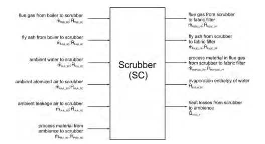
A valid result of the balancing needs to consider an overall point of origin, or reference state for the mentioned mass, energy and material flows (e.g. [19]). An example scrubber is shown in Figure 2 for illustrative purposes.
Figure 1: Balance modules for modeling a typical MSWI plant
Michael Beckmann, Tobias Widder
212
4. Specific values
Specific values are formed ratios depending on the values of a certain balance room.
Therefore, there is a categorical difference between
• operating figures, like the efficiency factor η and
• parameters, like the specific lime consumption in
Operating figures are real figures, thus dimensionless values such as the efficiency factor. Parameters, in contrast, contain a dimension, like pollutant concentrations in flue gas or operation material consumptions. In principle there is no law of formation for operating figures and parameters. Indeed they should represent a physical or che- mical issue to allow the comparison of different plants in accordance to the technical interpretation of them.
Regarding the balance boundary, it is enabled to determine the use at the input and the expen- diture at the output, which is needed to calculate the general specific value efficiency factor.
Thereby is obtained the evaluation of the local and timed defined system using the general ratio of use and expenditure:
Further information can be found in e.g. [9].
5. Preparation of equivalent values and energy exchange ratios
Energy in general is bound in different forms (electrical, thermal, chemical, nuclear…) which influence the conversion willingness of this respective energy form. Due to this fact, the question concerning the quality of different energy forms should be answered.
Figure 2: Example scrubber, incoming and out-going mass and energy flows
kg lime consumption
twaste
η= use
expenditure (1)
215 Balancing and Energy Efficiency of Waste Treatment Processes
One possibility to solve this challenging task is the establishment of equivalent va- lues and energy exchange ratios1 that have a quite similar function. Especially the use of common equivalent values provides the chance to compare different energy types with reference to the target energy being generated within a conversion pro- cess. This example question as to the equivalence of a primary energy ( ) with a certain delivered electrical energy results in
or also written as
In line with the afore-mentioned equivalent value for äel electrical energy, there are likewise equivalent values for thermal energy or electrical and thermal energy (coge- neration). If applicable they may be combined with other specific values in a beneficial way as illustrated for instance in [18].
It must be mentioned here that the (absolute) amount of electrical energy Pel strictly depends on the balance room. That means, supplying a plant process with a certain amount of primary (fuel) energy leads to different equivalent values - in contrast to the energy exchange ratios - for different balance circles in order to a changing elec- trical output. Therefore a fixed reference state is absolutely necessary, as shown in the following chapters.
6. Balance boundary module
The way to realize the balancing and finding the balance circles itself shall be illustrated for modules or subunits with the correlated balance circles. In practice, the smallest module in power plant technology with regard to the energetic balancing is an aggre- gate respectively apparatus like the feed water pump. For the energetic assessment of power plants such single aggregates are not of much interest, because it is clear that a low energy consumption of apparatuses takes a positive effect on the overall pro- cess, but this depends mainly on the manufacturer and not so much on the process optimization. In the course of the following consideration the next level modules are taken into account and let this module be represented through a firing. Incoming and out-going flows enter the balance room at the boundary. For clear determination of different balance boundaries – and the incoming and out – going mass, energy and material flows – an adequate identification convention is required. Within this article, the single balance systems are indicated with letters and the flows are indicated with numbers, which are associated with the balance system letter. In the following balance scheme this issue is illustrated for the firing:
m•ƒ •hu
Pel •äel= (2)
m•ƒ •hu
Pel •äel=
m•ƒ • hu äel =
Pel (3)
1 The substitution of one type of energy (e.g. natural gas enthalpy) through another ( e.g. generated vapor enthal- py) generally cannot be carried out at a 1:1 ratio. This means that the amount of energy to be substituted (e.g.
bound to the natural gas) can generally not be substituted through an equal amount of substitute energy but through a higher amount (e.g. bound vapor). This behavior is described through the so-called energy exchange ratio ER as the ratio of substitution energy to energy to be substituted. Usually ER > 1 and is dependent upon many factors. For clarity, ER = 1 in order to illustrate the principle of substitution or the energy recirculation.
The determination of ER is covered in ( [5], [6], [15], and [16]) [17].
Michael Beckmann, Tobias Widder
216
Hence the differentiation of use and expenditure is doubtless feasible and the efficiency factor (system A) can be formed by the energy flows of the firing:
Figure 3: Balancing room of the module firing
7. Balance boundary operation unit – paramount process subdivision –
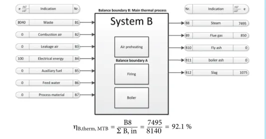
The combination of several modules results in an operation unit. Within this chapter, as an example the main thermal process is assumed, containing air system, firing and boiler. On the balance boundary of the main thermal process shall be annexed the relevant energy flows. Below, they are deposited with amounts by reason of a better visualization:
(4) ηA,firing = EΣ EA7in
Figure 4: Balancing room to form the efficiency factor of the main thermal process Σ B, in
ηB,therm, MTB= B8 = 8140 7495 92.1 %=
217 Balancing and Energy Efficiency of Waste Treatment Processes
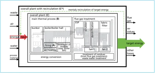
8. Balance boundary overall plant
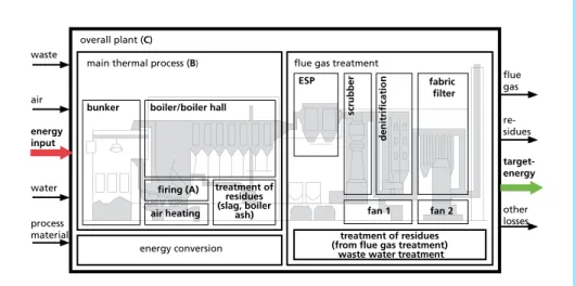
In order to reach the next expansion step of the boundary balance, the overall plant without regarding the energy supplied for the operation of the plant is to be discussed.
Figure 5 shows a simplified pattern of the systems A, B and C.
The efficiency factor can be obtained by using an analogous method to the previous chapters.
9. Balance boundary net overall plant
Each consumed auxiliary power that is internally generated by a (power) plant is on the one hand not available for potential purchaser, but on the other hand also not needed to be externally procured. Because of this context it makes sense to realize this internal recirculation in the balance as well. For this purpose the system C overall plant is augmented to the system D net overall plant. Due to the legal framework, in some existing plants it is more beneficial to put the gross electrical energy on the market and procure the auxiliary power from the grid then to receive it from the gross production [10]. In these cases the correct modeling of the balance rooms is to ensure. On the basis of the system C this case is illustrated in Figure 6 using the same schematic principle:
the arrow area can be seen as function of the energy flow amount (not true to scale);
empty arrow area means no energy flow at the crossing boundary.
Figure 5: Schematic for preparation of the overall plant efficiency factor
overall plant (C) main thermal process (B)
bunker boiler/boiler hall
flue gas treatment
flue gas waste
air
water
process material energy input
target- energy
other losses re- sidues
ESP fabric
filter
fan 1 treatment of residues (from flue gas treatment)
waste water treatment energy conversion
fan 2 scrubber denitrification
firing (A) air heating
treatment of residues (slag, boiler
ash)
Michael Beckmann, Tobias Widder
218
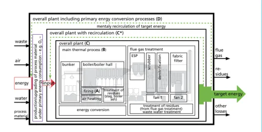
10. Balance boundary to create the primary efficiency factor
Operation of thermal waste treatment plants normally requires primary resources, such as unhydrated lime (which production spends primary energy) for the flue gas treatment. This circumstance leads to the necessity of upstream primary energy con- version processes as a complement to the overall plant process and demands a further expansion of the balance circle:
11. Balance boundary to create the net primary efficiency factor
Taking into account the exemplary consideration, necessary primary energy expenditure can be substituted through own generated target energy legitimates the establishment of a net primary efficiency factor. The motivation for this step is the fact that the pri- mary energy expenditure would not be needed if the waste destined for the treatment Figure 6: Schematic for preparation of the net overall plant efficiency factor
overall plant (C) overall plant with recirculation (C*)
main thermal process (B) bunker boiler/boiler hall
flue gas treatment flue
gas waste
air
water
process material
other losses
ESP fabric
filter
fan 1 treatment of residues (from flue gas treatment)
waste water treatment energy conversion
fan 2
scrubber denitrification
re- sidues
target energy energy input
mentaly recirculation of target energy
firing (A) air heating
treatment of residues (slag, boiler
ash)
Figure 7: Schematic for preparation of the primary efficiency factor
overall plant – C –
overall plant including primary enrgy conversion processes – D–
main thermal process – B –
bunker boiler/boiler hall
flue gas treatment flue
gas waste
air
water
process material
other losses
ESP fabric
filter
fan 1 treatment of residues – from flue gas treatment –
waste water treatment energy conversion
fan 2 scrubber denitrification
re- sidues
target energy energy input
firing – A – air heating
treatment of residues – slag, boiler
ash –
production/upgrading of process material under primary energy consumption – e.g. O
2 –
219 Balancing and Energy Efficiency of Waste Treatment Processes
Figure 8: Schematic for preparation of the net primary efficiency factor
overall plant (C)
overall plant including primary enrgy conversion processes (D)
main thermal process (B)
bunker boiler/boiler hall
flue gas treatment flue
gas waste
air
water
process material
other losses
ESP fabric
filter
fan 1 treatment of residues (from flue gas treatment)
waste water treatment energy conversion
fan 2 scrubber denitrification
re- sidues
target energy energy
firing (A) air heating
treatment of residues (slag, boiler
ash)
production/upgrading of process material under primary energy consumption – e.g. O
2 –
mentaly recirculation of target energy overall plant with recirculation (C*)
input
did not exist. Thus it is expedient to specify a net waste use, which can be calculated in turn through the mentally recirculation of generated target energy at the input of the balancing system.
12. Exemplary Efficiency factors for a classical household waste incineration
In the following section, these efficiencies will be calculated for the example of the classical waste combustion.
Attention: It is important to distinguish between the balance circle letters in the pre- vious sections and the following chapter, because they are not compellable identical.
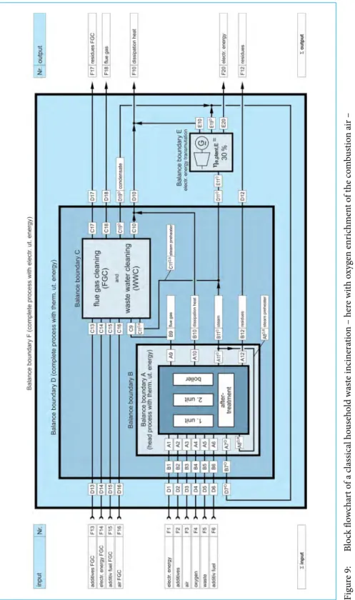
A significant prerequisite for the process evaluation is the systematic representation of partial processes with the determination of the balance limits and the respective material and energy flows which enter and leave in the balance circles. For thermal waste treatment processes, it has proved suitable to divide the first step of the total process into the partial steps of the so-called main thermal process and the flue gas purification and energy conversion (Figure 1). With the help of the overview in Figure 4 for the systematic description, the main thermal process of the classical waste incine- ration can be illustrated as a combustion unit (1st unit) and post-combustion (2nd unit).
A generation of effective thermal energy in the reactor is coupled with both units with respect to the balancing. It can be practical to include a possible post-treatment of the residual material in the first balance circle when comparing processes with an integra- ted melting of the residues ( e.g. high temperature gasification) for example. This then leads to a first balance circle A, as shown in Figure 9, which contains the main thermal process with effective thermal energy.
Michael Beckmann, Tobias Widder
220
Figure 9: Block flowchart of a classical household waste incineration – here with oxygen enrichment of the combustion air – Source: Beckmann, M. und Scholz, R.: Conventional Thermal Treatment Methods. In: Ch. Ludwig, S. Hellweg und S. Stucki. Municipal Solid Waste Management - Strategies and Technologies for Sustain- able Solutions. Springer-Verlag, 2002.
223 Balancing and Energy Efficiency of Waste Treatment Processes
The balance limit B encompasses the balance room A with an internal recirculation of the effective thermal energy, e.g. for the preheating of the air [5]. The flue gas and waste water treatment are included in the balance circle C. Together, the balance cir- cles of the main thermal process B and the flue gas/ waste water purification C form the balance circle of the total process D with the aim of the decoupling of the effective energy in balance circle F, results. Processes in balance circle F arranged in series before or after are of significance during the evaluation of the waste treatment. These so-called cumulative viewpoints can be achieved through the expansion of the balance circles and the fictional supplementation of each process (e.g. the energy conversion in a power plant or the oxygen generation in an air-separation unit). Next, the material balances (material, mass and energy balance) must be created for the individual balance circles. The energy balance then forms the basis for the determination of individual and total efficiencies. Figure 10 shows such an energy flow diagram for the case of a waste material with a lower heating value (hu = 6 MJ/kg). As mentioned before, the balance limit F was expanded through the addition of the processes for the oxygen generation and the primary energy conversion. The balance limit K then contains the total process with effective electrical energy and the consideration of the additional primary energy expenses.
Based on the systematic determination for the balance circles and the corresponding energy balances, it is now relatively easy to form the characteristic single and total efficiencies. With the current definition of the efficiency pursuant to equation (5), the following thermal plant efficiency for the balance room A results:
In the same way, the thermal plant efficiencies for consideration of the preheating of the air (balance circle B) and for the total process (balance circle D) can be determined.
Using the efficiency of the energy conversion from high-pressure steam to electrical energy (in this case = 30%, balance circle E), the electrical plant efficiency for the total process (balance room F, decoupling of effective electrical energy) results as:
(5)
ηt,plant,A = use = =
expenditure HA11°
Σ (HA1 to HA6) + HA7°+ HA8°,R 72.2 %
(6)
ηe,plant,F = use = =
expenditure EF20
Σ (HF1 to HF6) + Σ (HF13 to HF16) 19.9 %
Assuming an electrical efficiency for the electricity supply of = 40 % and a specific expenditure for the oxygen generation of 1.08 MJ electrical energy/kg oxygen, the ad- ditional expenditure in the form of the thermal and electrical primary energy efficiency can now be determined:
(7)
ηe,p,K = HE11° • ηe,a,E =
Σ (HK1 to HK6) + Σ (HK13 to HK16) + Σ (HK21 to HK24) 18.1 %
Michael Beckmann, Tobias Widder
224
Figure 10:Simplified energy flow diagram of the classical household waste incineration with regard to the primary energy resource expenditure – here with oxygen enrichment of the combustion air – Source: Beckmann, M. und Scholz, R.: Conventional Thermal Treatment Methods. In: Ch. Ludwig, S. Hellweg und S. Stucki. Municipal Solid Waste Management - Strategies and Technologies for Sustain- able Solutions. Springer-Verlag, 2002.
225 Balancing and Energy Efficiency of Waste Treatment Processes
In the above-mentioned example, the primary thermal efficiency for the balance room K results under the assumption that the electrical energy conversion (balance room) is omitted.
The primary energy could be saved or could supply a higher quality utilization in other processes, if no waste to be treated existed. This consideration leads, together with the explanation to Figure 9, to the net primary efficiency. For the example in Figure 10, the following net primary electrical efficiency results:
It should be mentioned, with regard to the cumulative balances, that negative energy balances can also result, e.g. the processes consumes more energy – with reference to the primary energy – than is generated through the waste treatment. It is in this case no longer a degree of efficiency but a corresponding degree of expenditure [5].
13. Energy quality in relation to production and consumption levels
In the beginning of this article the energy efficiency as quality criterion was introduced to assess energy conversion processes in industrial scale. The real challenge occurs at the interface between production and consumption. Quality of an energy type depends on the demand of this energy type – which has strong consequences for the economic result. An enterprise that has a high consumption of low calorific steam is not willing to pay a higher price for an energy type of high quality. They have just a certain de- mand and a supplier that delivers the requested energy reliable give them a high quality product. It is much more interesting to reduce the expenditure for the energy supply.
Therefore it is necessary to
• Improve the equivalence value (heat/power/heat and power), that means decreasing the losses
Minimizing the losses can be seen as the essential part of increasing energy efficiency, because another form of the efficiency factor is written as following:
(8) ηe,p,K = (HA*11° – HA*8°,R –HD*11°,R) • ηe,p,E* –EE* 20R–EF* 20R =
Σ (HK*2 to HK*5) + HK*13 14.0 %
(9) η = 1 – losses
expenditure
Identification and localization of losses does only work under comprising varying ba- lance rooms. In practice, this is one of the most complicated challenges in optimization of waste-to-energy-plants, although the basic equations are not difficult. This is one reason that constitutes the effort for the balance boundary determination.
As illustrating example an industrial creamery is mentioned, that needs heat at a low energy level for pasteurization and so on. This heat requirement cannot be completely
Michael Beckmann, Tobias Widder
226
saved by a technological procedure; principally it has to be generated by an energy conversion process. Maybe the needed energy level seems to be low-grade, but the demand itself is not low-grade and this simple consideration is very important for the process assessment. A near waste-to-energy-plant, that supplies the process heat, has an assumed heat generation capacity below the creamery demand. The waste-to energy plant now has two possibilities:
• Optimize the boiler parameters to reach a high electrical efficiency. In this case the creamery has to substitute the increased heat consumption gap with increased fuel usage in the additional process heat generator
• Minimizing the losses at matching boiler parameters, that does not allow a current generation, but give the maximal amount of steam demand from the waste fuel, resulting in a decreased additional fuel expenditure for the creamery
It will not be a step in the right direction to proclaim, the first way would be the more energy efficient and desirable way. One must take into consideration the higher amount of energy needed in the creamery that could also be converted in electrical energy – almost certainly with better process parameters and lower technical effort. This hast to be taken into account, depending on the energy exchange ratio.
The energy efficiency of a waste-to-energy-plant is always only as good as its place of location, which is responsible for the existence of suitable energy sinks. In this case, the energy type is not insignificant, but it is secondary. Finally it seems important to portend that besides economic interests, protection of resources does not occur auto- matically with a pretended high energy efficiency of a single plant.
Symbols Latin Letters
äel equivalent value for electrical energy AF waste (fuel)
Pel electrical power e specific energy E energy
ESP electrostatic precipitator hu lower heating value H enthalpy
mass flow (fuel/waste)
W waste
m•ƒ
227 Balancing and Energy Efficiency of Waste Treatment Processes
Greek Letters η efficiency
ηe electrical efficiency ηt thermal efficiency
14. References
[1] Beckmann, M., et al.: Bewertung der Energieeffizienz in Anlagen zur thermischen Abfallbehand- lung. Stellungnahme des Ausschusses VDI 3460. In: K. J. Thomé-Kozmiensky und M. Beckmann.
Energie aus Abfall - Band 2. TK Verlag Karl Thomé-Kozmiensky, 2007.
[2] Beckmann, M., et al.: Classification of Waste-to-energy Plants in Terms of Energy Recovery.
VGB PowerTech. 2007, Bd. 87, 10.
[3] Beckmann, M., et al.: Optimierung von Müllheizkraftwerken durch Einsatz eines Online-Bilan- zierungsprogramms. In: K. J. Thomé-Kozmiensky (Hrsg.). Optimierung der Abfallverbrennung 2. TK Verlag Thomé-Kozmiensky, 2005, S. 219 - 239.
[4] Beckmann, M. und Horeni, H.: Möglichkeiten zur Optimierung von Müllverbrennungsanlagen durch Einsatz eines Online- Bilanzierungsprogramms. In: VDI Wissensforum IWB GmbH (Hrsg.). 22. Deutscher Flammentag - Verbrennung und Feuerungen. Tagung Braunschweig, 21.
und 22. September 2005. VDI-Berichte Nr. 1888. Düsseldorf: VDI Verlag GmbH, 2005.
[5] Beckmann, M. und Scholz, R.: Conventional Thermal Treatment Methods. In: Ch. Ludwig, S. Hellweg und S. Stucki. Municipal Solid Waste Management - Strategies and Technologies for Sustainable Solutions. Springer-Verlag, 2002.
[6] Beckmann, M. und Scholz, R.: Energetische Bewertung der Substitution von Brennstoffen durch Ersatzbrennstoffe aus Abfällen bei Hochtemperaturprozessen zur Stoffbehandlung, Teil 1 und Teil 2. ZKG International. 1999, Bd. 52, Nr. 6 und Nr. 8.
[7] Beckmann, M. und Scholz, R.: Ermittlung der Energieeffizienz in Anlagen zur thermischen Abfallbehandlung. Zur Problematik von Äquivalenzwerten und der Berechnung des Heizwertes.
In: K. J. Thomé-Kozmiensky und M. Beckmann (Hrsg.). Energie aus Abfall - Band 2. TK Verlag Karl Thomé-Kozmiensky, 2007.
[13] Horeni, M. und Beckmann, M.: Investigation of Process Optimization Measures in MSWI Plants with an Online-Balancing Program. Porto, 2006. 7th European Conference on Industrial Fur- naces and Boilers (INFUB-7). CD-ROM.
[8] Beckmann, M. und Scholz, R.: Kapitel 5: Massen- und Energiebilanzen. In: (Autorenkollektiv) O. Gohlke, B. Neukirchen und J. Wiesner (Hrsg.). Werkzeuge zur Bewertung von Abfallbehand- lungsverfahren - Methoden und Ereignisse. Düsseldorf: VDI-Verlag GmbH, S. S. 18 - 34.
[9] Beckmann, M., Scholz, R. und Pohl, M.: Bilanzierung und energetische Bewertung von Verfah- ren zur Abfallbehandlung. In: K. J. Thomé-Kozmiensky und M. Beckmann. Energie aus Abfall - Band 9. Neuruppin: TK Verlag, 2012.
[10] European Commission.: Integrated Pollution Prevention and Control. Reference Document on the Best Available Techniques for Waste Incineration. 2006.
[11] Horeni, M., et al.: Ermittlung von Betriebsparametern in Abfallverbrennungsanlagen als Voraus- setzung für die weitere Optimierung. In: K. J. Thomé-Kozmiensky und M. Beckmann (Hrsg.).
Energie aus Abfall - Band 2. TK Verlag Karl Thomé-Kozmiensky, 2007.
[12] Horeni, M.: Möglichkeiten für die energetische Optimierung von Müllverbrennungsanlagen - Ent- wicklung, Erprobung und Validierung eines Online-Bilanzierungsprogramms. Clausthal-Zeller- feld : PAPIERFLIEGER, 2007. ISBN 3-89720-889-X.
Michael Beckmann, Tobias Widder
228
[14] Scholz, R., et al.: Zur systematischen Bewertung der Energieumwandlungen bei der thermischen Abfallbehandlung. Was ist Energieeffizienz? In: K. J. Thomé-Kozmiensky. Optimierung der Ab- fallverbrennung 1. TK Verlag Karl Thomé-Kozmiensky, 2004.
[15] Scholz, R. und Beckmann, M.: Substitution von Brennstoffen und Rohstoffen durch Abfälle in Hochtemperaturprozessen. In: 11. DVV-Kolloquium. Stoffliche und thermische Verwertung von Abfällen in industriellen Hochtemperaturprozessen. Braunschweig, 1998.
[16] Scholz, R., Beckmann, M. und Schulenburg, F.: Abfallbehandlung in thermischen Verfahren - Ver- brennung, Vergasung, Pyrolyse, Verfahrens- und Anlagenkozepte. B.G. Teubner-Reihe Umwelt, 1.
Auflage 2001.
[17] Schulenburg, F. und Scholz, R.: Energetische Bilanzierung von Verfahrenslinien aus mechanisch- biologischer und nachgeschalteter thermischer Abfallbehandlung. In: 13. ZAF-Seminar. Stoff- stromspezifische Abfallbehandlung im Hinblick auf thermische Verfahren. Braunschweig, 1998.
[18] Verein Deutscher Ingenieure (Hrsg.).:Richtlinie VDI 3460 Blatt 2 Emissionsminderung - Ener- gieumwandlung bei der thermischen Abfallbehandlung . August 2007.
[19] Verein Deutscher Ingenieure VDI (Hrsg.).: Richtlinie VDI 4661: Energiekenngrößen - Definitio- nen - Begriffe - Methodik. Berlin: Beuth-Verlag GmbH, 2003.