1
Sharpening of the ATLAS Muon Trigger for High Luminosity Operation at the LHC
J ¨org Dubbert, Oliver Kortner, Sandra Kortner, Hubert Kroha, J ¨org von Loeben and Robert Richter Max-Planck-Institut f¨ur Physik, F¨ohringer Ring 6, D-80805 M¨unchen, Germany
Abstract—The outer shell of the ATLAS experiment at the
LHC consists of a system of toroidal air-core magnets in order to allow for the precise measurement of the transverse momentum (p
T) of muons, which in many physics channels are a signature of interesting physics processes [1], [2]. For the precise determination of the muon momentum Monitored Drift Tube chambers (MDT) with high position accuracy are used, while for the fast identification of muon tracks chambers with high time resolution are used, able to select muons above a predefined p
Tthreshold for use in the first Level of the ATLAS triggering system (Level-1) trigger). When the LHC peak luminosity will be increased by a factor of 4–5 in about a decade from now (”SLHC”), an improvement of the selectivity of the ATLAS Level-1) triggering system will be mandatory in order to cope with the maximum allowed trigger rate of 100 kHz. For the Level-1) trigger of the ATLAS muon spectrometer this means an increase of the p
Tthreshold for single muons. Due to the limited spatial resolution of the trigger chambers, however, the selectivity for tracks above
∼20 GeV/c is insufficient for an effective reduction of the Level-1) rate. We describe how the track coordinates measured in the MDT precision chambers can be used to decisively improve the selectivity for high momentum tracks. The resulting increase in latency will also be discussed.
I. I
NTRODUCTIONFig. 1. Transverse momentum distribution of muons in the ATLAS muon spectrometer for various production channels.
Presented by J ¨org von Loeben (joerg.von.loeben@mpp.mpg.de) Robert Richter is the corresponding author (robert.richter@mpp.mpg.de)
While peak luminosities at the SLHC will be 4–5 times higher compared to the LHC design luminosity of 10
34cm
−2s
−1, the Level-1) trigger rate will have to remain at about 100 kHz. For this to happen the trigger selectivity for muons with high transverse momentum (p
T) has to be improved, the p
Tdistribution of muons falling off strongly with increasing p
T(Fig. 1). Total muon cross sections above p
Tvalues like 10, 20 and 40 GeV are 734, 47 and 3 nb, respectively.
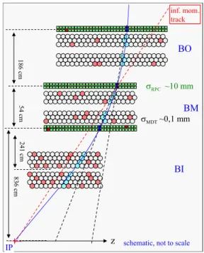
Fig. 2. Implementation of the Level-1) trigger in the muon barrel region.
The field lines of the B-field are perpendicular to the drawing plane.
Many interesting physics processes with small cross sections
have a signature of one (or more) muons above ∼ 20 GeV. The
capability to trigger on high-p
Ttracks was therefore one of
the principal requirements for the design of the ATLAS muon
spectrometer [1], [2]. For this purpose a system of trigger
chambers was implemented, covering the full acceptance of
the muon detector, capable to detect tracks above a predefined
p
Twithin a sufficiently short latency to be used in the ATLAS
Level-1) trigger. The latency is the time elapsed between
particle passage through the detector and arrival of the Level-1)
trigger at the frontend electronics of the various detector
elements. If a Level-1) trigger arrives later than the maximum
allowed latency, information in the front-end buffers of the
2
ATLAS subdetectors may be lost.
In the barrel and end-cap regions different chamber tech- nologies were chosen for triggering, adapted to the different configurations of the magnetic field in these detector domains.
In this article we describe the barrel region, where the Resis- tive Plate Chamber (RPC) technology is used.
II. P
ERFORMANCE LIMITS OFRPC
TRIGGER CHAMBERSRPCs use pick-up strips perpendicular to the z–direction (cf. Fig. 4) to sense the avalanches generated by traversing particles in the chamber gas, measuring the coordinates of the tracks along the bending direction of the magnetic field.
The time resolution of about 20 ns of the RPC chambers is sufficient to tag the beam crossings, which are spaced 25 ns from each other with about 95 % confidence. Fig. 2 shows the schematics of the Level-1) triggering system in the barrel region. RPC trigger chambers (marked in green) are positioned at three radial positions of the barrel, one in the outer detector layer (BO) and two in the middle layer (BM), below and above the middle MDT.
The slopes in the bending direction (η) of the track between inner and middle as well as between middle and outer RPC layer are compared to the slope of a track with infinite p
T, i.e. a straight line coming from the interaction point (IP), the difference of the slopes being a measure of p
T, where large deviations mean low p
T, while tracks with small deviation from a straight line mean high p
T. For the fast comparison of the slope of a track with the one of a infinite momentum track a system of coincidences between the pick-up strips of the three RPC layers is used (’coincidence matrices’).
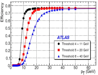
Fig. 3. Acceptance of the Level-1) trigger vs. pTfor three typical trigger thresholds. For the 20 and 40 GeV thresholds the transitions from 90–10% efficiency cover a wide pT-range, leading to high rates of unwanted triggers.
The width of the RPC strips of about 30 mm limits the precision of the slope measurement of the track. At a p
Tof 10, 20 and 40 GeV sagittas are 48, 24 and 12 mm, respectively, leading to a corresponding uncertainty of the threshold, as shown in Fig. 3. With a threshold setting of 20 GeV (square dots) the trigger is still accepting about 60 % of the 15 GeV and 15 % of the 10 GeV tracks. This leakage of below-threshold
muons into the trigger is by far not negligible because of the rapid fall-off of the inclusive muon cross section with p
T(see section I).
Replacing the present RPC chambers by ones with higher spatial resolution would be an obvious solution. This costly conversion could be avoided, however, if the high spatial resolution of the nearby MDT chambers could be used for the Level-1) trigger. For this to happen, the transfer of information from the MDT to the Level-1) triggering system must be sufficiently fast to remain inside the overall ATLAS trigger latency of 2.5 µs.
III. L
ATENCY LIMITATIONS OF THEATLAS L1
TRIGGERWhile peak luminosities at the SLHC will be 4-5 times higher compared to the LHC design luminosity of 10
34cm
−2s
−1, the Level-1) trigger rate will have to remain at about 100 kHz. The selectivity of the trigger has thus to be improved in order to retain only events with high p
Tmuons.
Improving the p
T-selectivity of the muon trigger means improving the precision of the track coordinates available for the Level-1) trigger decision. In the present ATLAS trigger hierarchy tracking information of the MDT is only used at the Level-2 trigger stage, where muon tracks are reconstructed using the precise MDT coordinates, leading to the rejection of more than 90 % of the Level-1) muon triggers.
Fig. 4. Tower structure of the muon spectrometer. In the barrel there are 12 towers along theη and 16 along the φ-direction (see text). Each tower only contributes a small rate of high-pT Level-1) triggers (below 100 Hz), resulting in low bandwidth requirements for the readout.
Due to considerable computing and data transfer overheads,
however, this result is only available after a latency of about
10 ms, more than three orders of magnitude beyond what is
acceptable for the latency of the Level-1) trigger. The chal-
lenge for an improvement of the Level-1) trigger is to design a
MDT readout scheme and an interface to the RPC trigger, able
to deliver more precise track coordinates and thus a refined
p
T-value inside the latency limits of the ATLAS trigger. The
present latency budget of 2.5 µs, adapted to the situation at the
original LHC, is insufficient for any refinement of the trigger
decision. For SLHC, however, an increase of the latency to
6.4 µs or even 10 µs will be implemented for the frontend
data storage of all subdetectors, providing considerable design
freedom for Level-1) trigger improvements.
3
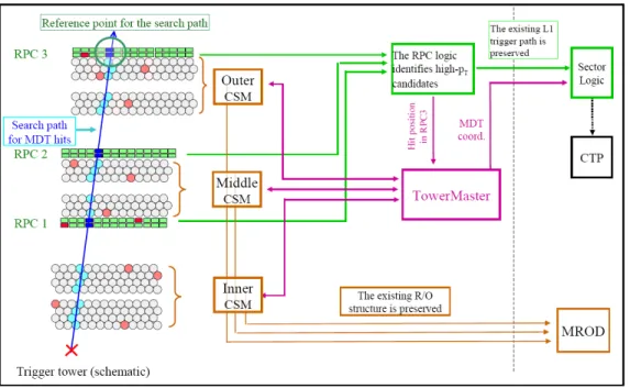
Fig. 5. Readout architecture to combine the precision track coordinates determined in the MDT chambers with the trigger information supplied by the RPC’s.
Only MDT hits along the search path are read out, those outside (mainly background hits fromγconversions) are ignored, reducing the amount of data to be transferred and thus the latency.
IV. I
NCLUSION OF THEMDT
PRECISION CHAMBERS INTO THEL
EVEL-1)
TRIGGER DECISIONA. Towerwise structure of the Level-1) trigger
The muon spectrometer is partitioned in projective towers along the direction of pseudo rapidity η and the azimuthal direction φ, where trigger and precision chambers are matched in size and location in each tower, see Fig. 4. High-p
Ttracks, following nearly straight lines, will mostly travel inside one projective tower, and therefore each tower can evaluate its high-p
Ttriggers independently from neighboring towers. The straight high-p
Ttracks define narrow search paths, where MDT hits, belonging to the triggering track must be located.
The readout of the MDT chamber can therefore be limited to a small number of tubes along the track trajectory (see left part of Fig. 5). The search path is communicated from the RPC to the MDT via the coordinate of the track in the outer RPC.
The present readout architecture of the MDT chambers is described in [3]. Being sequential and asynchronous with the TTC, it is too slow and not suited for the Level-1) refinement.
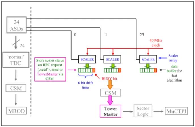
An additional, fast readout path of the MDT is therefore required, in parallel and independent of the existing one (see right part of Fig. 5). A simple scheme to have all drift times available at the same instant is shown in Fig. 6. Each of the 24 channels (i.e. tubes), served by an on–chamber readout card is connected to a scaler, which is started by each hit of the respective tube. If no trigger request is received from the RPC, the scaler goes into overflow and is automatically reset. If a request does arrive, all scalers are stopped, and the contents are transferred into a buffer for readout. Only the contents of scalers corresponding to tubes on the search path will be transferred to the TowerMaster for sagitta determination.
B. Interface between MDT and RPC
To interface the RPC logic with the MDT readout system a communication unit needs to be installed in each tower (”TowerMaster”). This unit needs to determine the explicite tube addresses along the search path (e.g. via a LUT) and send them to the on-chamber controllers of the MDTs, called Chamber Service Modules (CSM). The 3 CSMs, in turn, will read the drift times from the tubes on the search path and send them back to the TowerMaster. After reception of track co- ordinates from all 3 MDTs the TowerMaster could determine the sagitta, sending a confirm or a veto back to the RPC logic.
Alternatively, all coordinates could be forwarded downstream to the Sector Logic in the Counting Room for confirmation or rejection.
The standard (’slow’) MDT readout, connecting the CSMs to the ReadOut Driver (MROD), would remain unchanged (brown arrows in Fig. 5).
C. Synchronization of the readout with the TTC clock
The fast readout will be strictly synchronous with the TTC
clock. This means that the RPC request (’seed’) for precision
coordinates arrives at the MDT frontend a fixed number of
beam crossings after the passage of the triggering muon. This
way, due to the high time resolution of the RPC, the absolute
drift times in the MDT tubes become known. This allows for
a consistency check on the drift times in tubes subsequently
traversed by the muon, i.e. the sum of drift times must be
above a certain limit, otherwise the measurement might be
corrupted by a preceding background hit (γ-conversion). This
quality check of the drift time reading becomes particularly
important at high background rates, where conversion events
4
may occur at a high rate and may frequently degrade the drift time reading from a traversing muon.
Fig. 6. The determination of the drift times by individual scalers for each tube. The Amplifier-Shaper-Discriminator chip (ASD), serving 24 channels sends signals to a conventional TDC, storing the arrival times of the hits in a sequential way in a buffer, while a bank of 24 scalers, one for each channel, stores the same arrival times in a parallel way for fast access by the triggering system (see text).
D. Reduction of the drift time resolution
The resolution of the MDT drift time will be reduced from 12 to 6 bit, the resulting position resolution of the MDT of about 1 mm (RMS) being still about a factor 10 better than the one of the RPC, sufficient for a decisive sharpening of the Level-1) trigger threshold. Corrections for the non- linear radius to drift time (r–t) relation in the MDT gas and other small effects can be neglected at this level of precision.
With the reduction of the number of bits, data volumes and transmission delays are reduced. In addition, data redundancy and format overheads will be reduced to the strict minimum.
An analysis of the time behavior of such a readout model shows that a latency of 4.5–5.5 µs could be achieved and thus would be a realistic option for the upgrade of the muon Level-1) trigger for the SLHC. A significant advantage of this scheme would be that the existing RPC trigger chambers, except electronics, would not need any modifications.
A similar upgrade scheme could also be applied to the Level-1) trigger in the end-cap region where trigger chambers of the TGC type are used [1], [2]. Because of the different geometry of the toroidal magnetic field and the different location of trigger and MDT chambers, however, a modified architecture and specialized algorithms will have to be used.
V. S
UMMARYThe upgrade scheme for the Level-1) muon trigger described above allows to sharpen the threshold of the high-p
Ttrigger by about an order of magnitude, sufficient for the luminosity increase envisioned for the SLHC. This way the existing RPC trigger chambers can stay in place. The readout electronics of RPC as well as MDT will need complete replacement. A number of readout units along the data path will have to be designed to contain local intelligence and the possibility for precise timing adjustment in order to fulfill the synchronicity requirement, mentioned above.
R
EFERENCES[1] ATLAS Collaboration, Technical Design Report for the ATLAS Muon Spectrometer, CERN/LHCC/97-22, May 1997.
[2] The ATLAS collaboration, The ATLAS Experiment at the CERN Large Hadron Collider, JINST 3 S08003 (2008)
[3] Y. Arai et al., ATLAS Muon Drift Tube Electronics, JINST 3 P09001 (2008)