Alignment of the ATLAS Muon Spectrometer with Muon Tracks
Bernhard Bittner
1, Steffen Kaiser
1, Oliver Kortner
1, Sergey Kotov
1, Hubert Kroha
1, Igor Potrap,
1Robert Harrington
2, Jeremy Love
2, Nigel Nation
2on behalf of the ATLAS Muon Collaboration
Abstract— The ATLAS muon spectrometer uses three layers of precision drift-tube chambers to measure muon momenta accurately up to the TeV scale in an air-core toroid magnet system providing a field integral of 2.5 to 7 Tm. In order to achieve the required momentum resolution of better than 4% for transverse momenta below 400 GeV/c and of 10% at 1 TeV/c, the relative positions of the muon chambers must be known with 30 µm accuracy. A system of optical alignment sensors monitors relative movements of the chambers with a few micrometers accuracy.
It is capable of measuring the relative chamber positions with an accuracy better than 30µm after it has been calibrated with straight tracks. These will be provided by special runs with the magnets turned off. We present results of Monte-Carlo studies for the alignment with straight tracks recorded with proton-proton collisions at the LHC and cosmic muon data.
Index Terms— ATLAS detector, muon spectrometer, drift tubes, alignment, tracks, muon.
I. INTRODUCTION
T
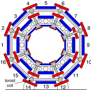
HE ATLAS muon spectrometer is instrumented with three layers of so-called ”Monitored Drift-Tube” (MDT) cham- bers for the precise measurement of muon tracks in a toroidal magnetic field of 0.4 T average field strength. The MDT chambers consist of two triple or quadruple layers of aluminium drift tubes with 30 mm diameter and 0.4 mm wall thickness mounted on either side of an aluminium space frame. The tubes are filled with argon and carbon dioxide in the mixing ratio 93:7 at 3 bar absolute pressure. Operated at 3080 V voltage, corresponding to a gas gain 20,000, the tubes provide an average single-tube resolution of 80μm. Due to the high 20μm mechanical positioning accuracy of the sense wires inside a chamber the tube resolution leads to 35μm spatial resolution of the chambers. If the three layers of MDT chambers are aligned with an accuracy of 30 μm, a momentum resolution better than 10% is achived up to pT = 1 TeV/c. The MDT chambers measure track positions only in the bending plane of the toroid magnet. The missing coordinate in the direction of the field is provided by so-called ”Resistive Plate” (RP) and”Thin Gap” (TG) trigger chambers in the barrel and the end caps respectively [1].
The barrel part (|η| < 1) of the muon spectrometer is arranged in 16 sectors (see Figure 1). Relative movements of the chambers within a sector are monitored with 10μm resolution
1Max-Planck-Institut f¨ur Physik, F¨ohringer Ring 6, 80805 Munich, Germany
2Boston University, 590 Commonwealth Avenue, Boston MA 02215, USA
4 5 6
14 12
1 9
16 10
2 8
3 7
15 11
13
toroid coil
Fig. 1. Schematic of the the cross section of the ATLAS muon spectrometer.
The muon chambers shown as blue and red boxes are arranged in 16 towers.
by a system of optical alignment sensors. The positions of the chambers must be determined once by means of straight muon tracks [2].
As we shall describe in this article, straight cosmic muon tracks can be used to align the top sectors (3-7) and the bottom sectors (11-15) with the required accuracy. There are not sufficient horizontal muon tracks in the other sectors in the ATLAS cavern 100 m below ground. Straight muon tracks to align the whole barrel muon spectrometer will be provided in a special run in which muons fromppcollisions will be recorded with the toroid magnet turned off. Our Monte-Carlo studies for this run show that the positions of all muon chambers can be measured with the data of this special run.
II. MOMENTUM MEASUREMENT AND ALIGNMENT REQUIREMENTS
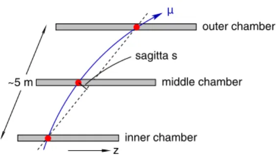
Muon tracks are measured by three layers of MDT chambers as sketched in Figure 2. These provide three track points with 35 μm accuracy, one at the entrance of the spectrometer, one in the middle, and one at the exit. Tese three points are used to measure the sagitta which is defined as the deviation of the track point in the middle from the straight interconnection of the inner and outer track points. The sagitta s is inversely
middle chamber
inner chamber
outer chamber µ
sagitta s
~5 m
z
Fig. 2. Sketch of the sagitta measurement performed in the ATLAS barrel muon spectrometer
proportional to the transverse momentum and about 500μm for 1 TeV muons. As the fractional momentum resolution equals the fractional sagitta resolution, a 10% momentum resolution corresponds to 10% sagitta resolution which is 50μm at 1 TeV.
The track point resolution of 35μm contributes 40 μm to the sagitta resolution. So the contribution from the misalignment of the three chambers should be less than 30μm.
III. STRAIGHT-TRACK ALIGNMENT ALGORITHM
In this section we describe the algorithm used for the internal alignment of a barrel sector with straight muon tracks. We begin with the reconstruction of a straight muon trajectory.
As depicted in Figure 3 we use a coordinate system in which x is parallel to the anode wires of the tubes of the MDT chambers, y points in radial direction outwards from the pp interaction point, andzis parallel to the direction of the proton beams. The muon trajectory can be parametrized as straight lines in thexz andyzplanes:
x=mxz+bx, y=myz+by.
The MDT chambers measure the trajectory in the yz plane.
The trajectory in thexyplane is measured by the RPC trigger chambers.
mxandbxare determined by minimizing χ2RP C=H
h=1
[xh−(mxzh+bx)]2 σh2
00000000000000000000 11111111111111111111 00000000000000000000 11111111111111111111
00000000000000000000000 11111111111111111111111
y
middle chambers
inner MDT chamber z
µ
outer chambers
MDT MDT
MDT RPC RPC
RPC
Fig. 3. Schematic drawing of a straight muon track traversing three muon chambers of a sector. On the right the drift circles in the tubes crossed by the muon are depicted.
whereH denotes the number of hits in the RPC chambers,xh
andzhare thexandzcoordinates of thehth hit. While the RPC chambers provide cartesian hit coordinates, the MDT chambers only provide drift radii r(tk) which are measurements of the track distances with an uncertaintyσ(r(tk)). One therefore has to minimize
χ2MDT =
K
k=1
[r(tk)−dk(mx, bx, my, by)]2
σ(r(tk))2 (1) with dk(mx, bx, my, by) being the distance of the track from the anode wires of the hit tube and K being the number of hit tubes. Letwyk andwzk be the wire coordinates of the kth hit at the reconstructed hit position wxk along the wire. Then dk(mx, bx, my, by)is given by
dk(mx, bx, my, by) = |mywzk+by−wyk| 1 +m2y
= sgn(mywzk+by−wyk)· mywzk+by−wyk
1 +m2y
(2) LetC(k)label the chamber to which thekth hit belongs. When the MDT chambers are displaced from their nominal positions by δyC in y direction and δzC in z direction and rotated by small angles φxC,φyC, and φzC around the x,y, andz axes, wyk andwzk have to be replaced by
wyk:=wyk+δyC(k)−wzkφxC(k)+wxkφzC(k), wzk:=wzk+δzC(k)+wzkφxC(k)−wxkφyC(k)
in Equation (2).
dk is neither linear in the track parameters nor in the align- ment parameters. It can be linearized without loss of precision in the following way. Firstly as the geometry of the chambers is known, the restriction of the track fit to each chamber provides us with the sgn term. Secondly as the inner and outer muon chambers are 5 m apart, the slope is reconstructed with permille accuracy even for the limited mounting accuracy of the order of a millimeter. Let sk denote the sgn(mywzk +by−wyk) as obtained from the restricted track fit and m¯y be the slope reconstructed in a first pass track fit before any alignment corrections have been applied. Then
dk(mx, bx, my, by) ≈ skmywzk+by−wyk
1 + ¯m2y + sk
1 + ¯m2y
[−δyC(k)+ ¯myδzC(k)
+(1 + ¯my)wzkφxC(k)
−m¯ywxkφyC(k)−wxkφzC(k)]
=: d¯k(mx, bx, my, by)
to good approximation. We replace dk by d¯k in Equation (1).
In order to determine the alignment parameters we minimize the sum of theχ2MDTs of the collected tracks in the track and
1 2 3 4 5 6
η=0 η=1
y
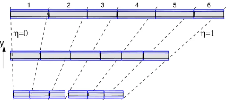
Fig. 4. Schematic of one half of a barrel sector of the muon spectrometer.
Theppinteraction points is in the lower left corner. The dashes lines indicate the tower structure inside a sector.
alignment parameters. During the fit we impose the condition on the alignment parameters that centre of gravity of the sector is unaltered. Due to the linearization of dk the minimization problem can be solved analytically.
IV. APPLICATION TO STRAIGHT TRACKS INppCOLLISIONS As mentioned in the introduction, the optical alignment system monitors chamber movements with an resolution of a few micrometers. The positions of the chambers within a sector must be determined with straight muon tracks. In order to provide straight muon tracks, ATLAS plans a dedicated run in which the toroid magnet of the spectrometer will be switched off during the operation of the LHC. The magnetic field in the inner detector will be turned on to permit the measurement of muon momenta. The transverse muon momentum spectrum is steeply falling with the transverse momentum. So most of the muon above a pT thresholds have a momentum close to the threshold value. We chose apT threshold of 20 GeV/c to limit multiple scattering and simulated 100,000 single muon tracks withpT = 20 GeV/c in one sector of the muon spectrometer to study our alignment algorithm.
1 2 3 4 5 6
m]μ[σ
0 10 20 30 40 50 60 70
80 Large Sector
Small Sector
tower index
Fig. 5. Accuracy of the sagitta correction after the alignment with 100,000 straight muon tracks ofpT=20 GeV/c in the barrel.
The chambers within a barrel sector of the muon spectrom- eter are arranged in towers of three chambers are indicated by the dashed lines in Figure 4. Most of the straight muon tracks are fully contained in a tower. But there are also straight tracks linking neighbouring towers especially at large rapidities. Our Monte-Carlo studies show that the individual towers can be aligned with the required accuracy. Yet the angular spread of the tracks linking two neighbouring towers is too small to align neighbouring towers with respect to each other with the same accuracy. This problem can be cured by imposing constraints on the movements of the chambers iny direction of the order of 200-300 μm. Such contraints will be provided by an optical alignment system monitoring the planarity of the individual chamber layers within a sector.
Figure 5 shows the accuracy of the alignment correction on the sagitta provided by our straight-track alignment algorithm with 100,000 muon tracks of pT=20 GeV/c. An accuracy of 10 μm is achieved for the large sectors drawn in blue in Figure 1. The accuracy decreases to 30μm in the small sectors drawn in red in Figure 1 due to multiple scattering of the muon in the toroid coils.
V. APPLICATION TO COSMIC MUON DATA
During the past year ATLAS recorded millions of cosmic muon data. These data can be used to align the top and bottom sectors of the barrel muon spectrometer. We applied our algorithm to 400,000 muon tracks traversing the top sector 5 of the spectrometer. As the angular spread of cosmic muons is larger than that of straight muons from pp interactions, no constraints from the optical system on the vertical displacement of the chambers have to be applied. As shown in Figures 6, we were able to align the three inner towers of the sector with 30μm resolution and better than 80 μm for the outer towers.
We excluded the outermost tower from our alignment fit due to lack of statistics of muons connecting the outermost chambers with the rest of the chambers of the sector.
tower index
1 2 3 4 5 6
m]μ[σ
0 20 40 60 80 100 120 140
Sector 5A
Fig. 6. Accuracy of the sagitta correction after the alignment with 400,000 straight cosmic muon tracks in the top sector 5 of the barrel muon spectrometer.
nominal geometry 250
200 150 100 50
−10 −80 −6 −4 −2 0 2 4 6
8 10 residuals [mm]
Middle chamber BML−3C−05
Mean (−0.566±0.016) mm Sigma (0.660±0.022) mm
Middle chamber BML−3C−05
−10 −8 −6 −4 −2 0 2 4 6 8 10
residuals [mm]
50 150 200 250 350
0 100
300 track based alignment
Sigma (0.351±0.014) mm Mean (0.002±0.010) mm
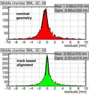
Fig. 7. Track residual in a middle chamber of the top sector before the alignment with track (top) and after the alignment with track (bottom).
Two tests were performed to verify the correctness of our alignment constants. The first test is a self-consistency test in which we select cosmic muons pointing to the imaginary pp interaction point. The mean value of the residuals in the middle chamber of a tower is 23 of the bias on the sagitta.
Figure 7 shows that the bias on the reconstructed sagitta reduces from 32 ·0.566 mm=0.849 mm before the track alignment to
32·0.002mm=0.003 mm after the track alignment. As expected the bias on the sagitta is minimized after the application of the alignment corrections provided the track alignment algorithm.
In the second test we compared our measurement of the distances of the chambers within the inner and outer layer of the top sector with a measurement of the chamber distances using a feeler gauge. Figure 8 shows a clear correlation between the distances measured in the track alignment procedure and the mechanical measurements. The distances of the outer chambers agree within 85μm, but a shift of 190μm is observed between the track alignment and the mechanical measurement. The discrepancy is caused by the fact that chamber distances are measured between mounting rods of the inner chambers while distancese between adjacent tubes of the outer chambers are measured. New measurements of the distances of adjacent tubes of the inner chambers are planned to verify the explanation.
VI. SUMMARY
An algorithm for the alignment of the sectors of the bar- rel ATLAS muon spectrometer with straight tracks has been presented in this article. Monte-Carlo studies show that the algorithm provides sagitta correction with the required accuracy of 30 μm or better for 100,000 muon tracks with pT ≥ 20GeV/c. The application to cosmic muon data recorded with the top sector of the ATLAS muon spectrometer confirms the accuracy of the alignment corrections provided by the described straight-track alignment procedure.
Mechanical measurement [mm]
16 17 18 19 20
Trackalignmen
6 7 8 9 0
1 1 1 1 2
t[mm]
outer chambers inner chambers
Fig. 8. Comparison of the distance of the inner and outer chambers as measured by the alignment algorithm with mechanical measurements using a feeler gauge.
ACKNOWLEDGEMENTS
We would like to thank G. Bobbink for providing with the results of the mechanical distance measurements.
REFERENCES
[1] G. Aad et al. The ATLAS Experiment at the CERN Large Hadron Collider.
JINST, 3:S08003, 2008.
[2] C. Amelung et al. The ATLAS muon alignment system. Prepared for 1st LHC Detection Alignment Workshop, Geneva, Switzerland, 4-6 Sep 2006.