Prepared for submission to JINST
New High-Precision Drift-Tube Detectors for the ATLAS Muon Spectrometer
H. Kroha,
a,1R. Fakhrutdinov
bA. Kozhin
ba
Max-Planck-Institute for Physics, Föhringer Ring 6, 80805 Munich, Germany
b
Institute for High Energy Physics, Science Square 1, Protvino, 142281 Russia E-mail: kroha@mppmu.mpg.de
Abstract: Small-diameter muon drift tube (sMDT) detectors have been developed for upgrades of the ATLAS muon spectrometer. With a tube diameter of 15 mm, they provide an about an order of magnitude higher rate capability than the present ATLAS muon tracking detectors, the MDT chambers with 30 mm tube diameter. The drift-tube design and the construction methods have been optimised for mass production and allow for complex shapes required for maximising the acceptance. A record sense wire positioning accuracy of 5 µm has been achieved with the new design. 14 new sMDT chambers are already operational in ATLAS, further 16 are under construction for installation in the 2019-2020 LHC shutdown. For the upgrade of the barrel muon spectrometer for High-Luminosity LHC, 96 sMDT chambers will be contructed between 2020 and 2024.
Keywords: ATLAS detector, muon detectors, drift tubes
1 Corresponding author.
Contents
1 Introduction 1
2 Performance of the sMDT chambers 2
3 Drift tube design and fabrication 5
4 sMDT chamber construction and test 5
1 Introduction
The ATLAS Monitored drift tube (MDT) chambers [1] provide reliable muon tracking with excellent spatial resolution and high tracking efficiency independent of the track incident angle. Small- diameter muon drift tube (sMDT) chambers with a tube diameter of 15 mm, i.e. half of the tube diameter of the MDT chambers, have been developed to cope with the higher background irradiation rates at High-Luminnosity LHC (HL-LHC) and future hadron colliders and to fit into small available spaces as it is necessary for the upgrades of the ATLAS muon spectrometer. At the same time, the chamber construction methods have been optimised for mass production with significant savings in component cost, construction time and manpower compared to the ATLAS MDT chambers while providing the same reliability and mechanical robustness and even higher sense wire positioning accuracy. For the ATLAS precision muon tracking detectors a wire positioning accuracy of 20 µm (rms) is required. Standard aluminium tubes are used, with a wall thickness of 0.4 mm like for the MDT chambers. The sMDT chambers are operated in ATLAS with the same gas mixture, gas pressure and gas gain as the MDT chambers. Table 1 shows a comparison of the MDT and sMDT operating parameters. The drift time spectra are shown in the left-hand part of figure 1.
The maximum drift time of the sMDT tubes is only 175 ns compared to about 720 ns of the MDT chambers leading, together with the twice smaller cross section exposed to the radiation, to about 8 times lower occupancy and a linear space-to-drift time relationship with the standard MDT drift gas Ar:CO
2(93:7) at 3 bar pressure.
A full-scale sMDT prototype chamber of trapezoidal shape has been constructed and tested in the H8 muon beam and in the Gamma Irradiation Facility (GIF) at CERN in 2010 [4]. The chamber has been operated in the ATLAS cavern in 2012. In 2014, two sMDT chambers [5], each with two integrated RPC chambers, have been installed in access shafts in the feet region of the ATLAS barrel muon spectrometer (so-called BME chambers) and are in operation since the start of LHC run 2. In January 2017, 12 new sMDT chambers have been installed inside the detector feet in the bottom sectors of the barrel muon spectrometer (so-called BMG chambers) [6] and are in operation for the data taking in 2017.
The construction of further 16 sMDT chambers with integrated triplet RPC trigger chambers
has started. They will be installed under very tight spatial constraints on the toroid magnet coils at
Table 1. Material and operating parameters of ATLAS sMDT chambers [2] compared to the MDT cham- bers [1].
Type MDT sMDT
Tube outer diameter 29.970 mm 15.000 mm
Tube wall thickness 0.4 mm 0.4 mm
Wire diameter 50µm 50µm
Wire pitch 30.035 mm 15.099 mm
Gas mixture Ar:CO2(93:7) Ar:CO2(93:7) Gas pressure 3 bar (abs.) 3 bar (abs.)
Gas gain 2·104 2·104
Wire potential 3080 V 2730 V
Maximum drift time 720 ns 175 ns
Wire positioning accuracy 20µm (rms) 10µm (rms)
Figure 1. Left: Drift time spectra of MDT (green) and sMDT tubes (grey) together with the prediction of a GARFIELD simulation for sMDT tubes (red line) [2]. Right: Measurements of the gas gain of MDT and sMDT tubes relative to the nominal gas gain G
0= 20000 as a function of the γ background rate at the Gamma Irradiation Facility at CERN compared to predictions based on the Diethorn formula [7].
the ends of the inner barrel layers (so-called BIS chambers) in the long LHC shutdown in 2019-2020 in order to improve the trigger efficiency and the rate capability of the chambers in the transition regions between barrel and endcaps. They have rather complex shapes in order to maximise the acceptance in the overlap region between the barrel part the muon spectrometer and the inner endcap layer and can only be built with the assembly methods developed for the sMDT chambers. This upgrade of the muon spectrometer serves as pilot project for the complete replacement of the MDT chambers in the by sMDT-RPC chamber modules enhancing the rate capability of the tracking and trigger chambers by about an order of magnitude and increasing the barrel muon trigger efficiency and robustness for operation at HL-LHC. The installation of new triple thin-gap RPCs of only 5 cm thickness becomes possible only by replacing the BIS MDT chmabers by sMDT chambers which have about half the height. 96 new BIS sMDT chambers will be constructed for this purpose in the years 2020-2024.
2 Performance of the sMDT chambers
The performance of MDT [3] and sMDT chambers [2] has been extensively studied at the Gamma
Irradiation Facility at CERN using the existing ATLAS MDT readout electronics with bipolar
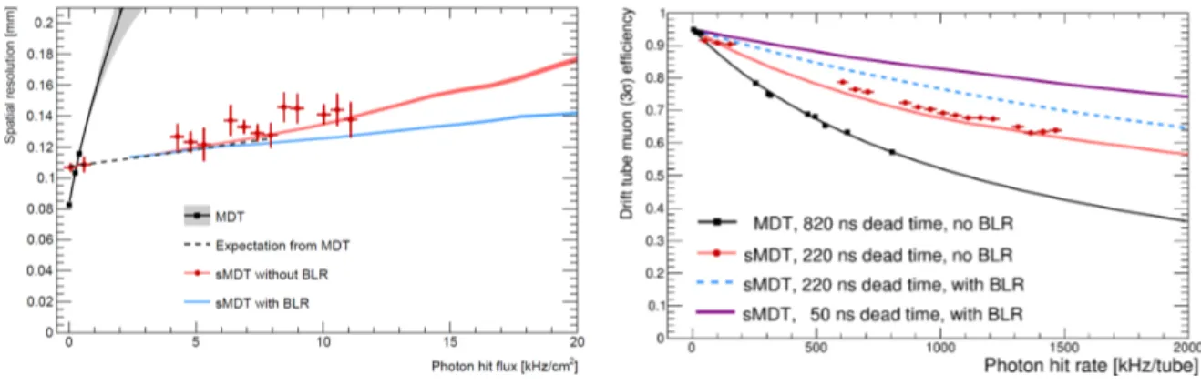
Figure 2. Average spatial resolution (left) and muon detection efficiency (within 3σ of the reconstructed track) of MDT and sMDT drift tubes measured at the Gamma Irradiation Facility at CERN as a function of the γ background rate using standard MDT readout electronics with bipolar shaping. The same front- end electronics scheme and parameters will be used for MDT and sMDT chambers at HL-LHC. Further improvement of the sMDT drift tube spatial resolution at high background rates and space charge densities can be achieved by employing additional fast baseline restoration (BLR) in order to suppress signal pile-up effects (blue curves) [8] which is not needed for operation at HL-LHC.
signal-pin (gold plated)
signal-cap (brass)
O-Ring (ø4x1,5)
gas-connector (PBTP)
crimptube (copper)
plastic-insulator (PBTP)
O-ring (ø10x2)
stopper (PBTP)
drift-tube ø15x0,4 (aluminium)
twister ø5 (brass)
ground-screw (gold plated)
ground-pin (gold plated) O-ring
(ø4x1,5)
Distance of wire from nominal position [mm]
−0.04 −0.02 0 0.02 0.04 0
20 40 60 80 100 120 140 160 180
= (4.8±0.2) μm σ
(RMS: 5.5 μm)
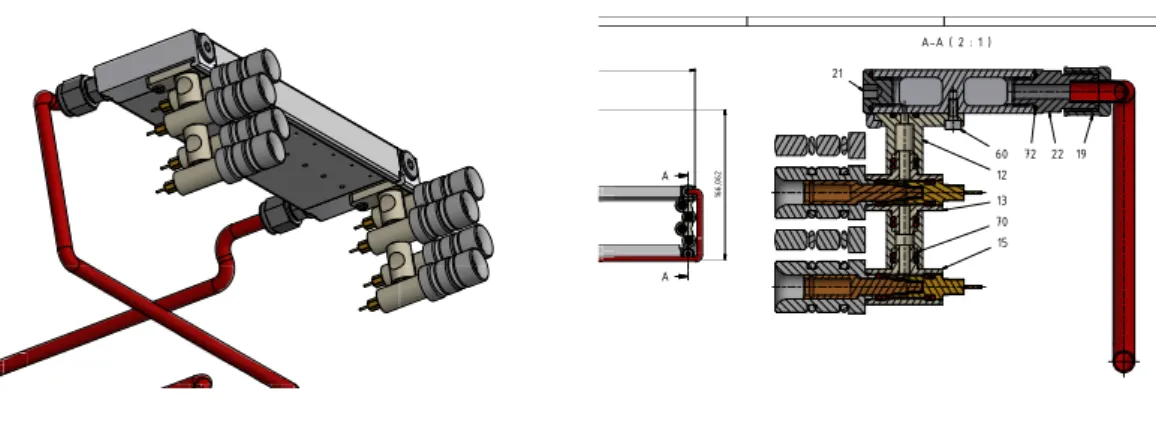
Figure 3. Left: Cross section of an sMDT endplug with internal wire locator and external reference surface for tube and wire positioning during construction and for wire position measurement. Right: Residuals of the sense wire positions measured at both ends of a BMG sMDT chamber with 356 tubes with respect to the nominal wire grid. The width of the distribution includes the accuracy of the coordinate measureing machine of about 2 µm.
shaping. For the (s)MDT amplifier-shaper-discriminator (ASD) chips at HL-LHC the same specifi-
cations will be used as for the present system. The MDT chambers can be operated up to background
rates of 500 Hz/cm
2and 300 kHz per tube. At background rates above 500 Hz/cm
2, the gas gain
A-A ( 2 : 1 )
A
A
15 21
22 19
166,062
60 12 13 70
72
![Table 1. Material and operating parameters of ATLAS sMDT chambers [2] compared to the MDT cham- cham-bers [1].](https://thumb-eu.123doks.com/thumbv2/1library_info/4005638.1540826/3.892.146.729.179.567/table-material-operating-parameters-atlas-smdt-chambers-compared.webp)