An Efficient Method to Determine the
Space-to-Drift-Time Relationship of the ATLAS Monitored Drift Tube Chambers
M. Deile∗, N. Hessey†, O. Kortner‡, H. Kroha‡, J ¨org v. Loeben‡, A. Staude§
∗
CERN, CH-1211 Geneva 23, Switzerland,
∗NIKHEF Amsterdam, The Netherlands,
‡Max-Planck-Institut f¨ur Physik, M¨unchen, Germany
§Ludwig-Maximilians-Universit¨at-M¨unchen, Germany
Abstract—The ATLAS experiment at the Large Hadron Col- lider (LHC) at CERN is currently being assembled to be ready to take first data in 2008. Its muon spectrometer is designed to achieve a momentum resolution of better than 10%
up to transverse muon momenta of 1 TeV. The spectrometer consists of one barrel and two endcap superconducting air-core toroid magnets instrumented with three layers of precision drift chambers as tracking detectors and a dedicated trigger system.
Detailled studies have been performed with a new approach of the autocalibration, a method to determine the space-to-drift- time relation of the ATLAS MDT chambers, and are presented.
I. INTRODUCTION
The ATLAS muon spectrometer is based on three super- conducting air core toroid magnets–one for the barrel and one for each of the two end caps. With a mean bending power of 3 Tm in the barrel and 5 Tm in the end caps, muon tracking chambers with an accuracy better than40μm are required to achieve the spectrometers design resolution of ΔpμT/pμT <2−3%forpμT <200GeV/c andΔpμT/pμT <10%
for pμT = 1 TeV/c. Three layers of Monitored Drift Tube (MDT) chambers are used as precision trackers in the muon spectrometer. Each MDT chamber consists of two multilayers of three or four layers of drift tubes glued to both sides of an aluminum support frame (cp. fig. 1). Each of the layers include up to 72, 1–6 m long tubes, a chamber has a maximum number of 432 drift tubes.
For muon momenta larger than 300 GeV/c, the calibration of the space to drift time relationship of the MDT chambers is—
beside the spectrometer alignment—the main contribution to the momentum resolution (cp. fig. 2) and has to be known with an accuracy better than 20μm. The space to drift time, r(t), relation depends on the operating and environmental parameters of the chambers like the temperature, gas mixture, magnetic field, and the background radiation, thus necessitat- ing an hourly recalibration of the spectrometer.
II. ANALYTICALAUTOCALIBRATION
With current status of the simulation programs it is not possible to calculate the r(t) relation from the operating and environmental data with sufficient accuracy. Therefore, the calibration is performed with the chamber data itself. Using
Manuscript submitted November 23, 2007
RO
HV Drift Tube
μ
0.05 mm
r
30 mm
Length: 1 − 5 m Layers
W−Re Wire Al Tube Wall
Alignment Rays Width: 0.7 − 2.2
m Gas Mixture: Ar/CO2 (93/7) Gas Gain: 2 x 10 Pressure: 3 bar
4
Fig. 1. Schematic view of a barrel Monitored Drift Tube (MDT) chamber
0 1 2 3 4 5 6 7 8 9 10 11 12
10 102 103
pT (GeV)
Contribution to resolution (%)
Tube resolution and autocalibration Chamber alignment
Multiple scattering Energy loss fluctuations Total
|η| < 1.5
Fig. 2. Contributions to the transverse momentum resolution of the ATLAS barrel muon spectrometer [1]
the redundant measurement of muon tracks in the tube layers of MDTs, the r(t) relation can be improved by an itera- tive method (autocalibration). The best performing algorithm which reaches an accuracy better than20μm across the whole spectrometer is the so-called analytical autocalibration. It uses an initial r(t) relation with an accuracy of about 200 μm, which can be obtained for example by integrating the drift time spectrum [2], to reconstruct straight muon tracks in an MDT chamber or, dependending on the muon momentum, in
2007 IEEE Nuclear Science Symposium Conference Record N15-275
1-4244-0923-3/07/$25.00 ©2007 IEEE. 685
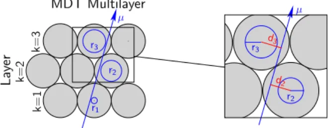
μ
d2 d3 r3
r2
r2
μ
r1
r3
MDT Multilayer
Layer k=3k=1k=2
Fig. 3. Reconstruction of a straight muon track in an MDT multilayer
one multilayer.
The method uses the track residuals
Δ(tk) =r(tk)−dk (1) (k:=number of hit tube, see fig. 3) to correct the r(t) relation from the i-th iteration. The idea of this method is, not only to correct the r(t) relation by the mean value of residuals of sev- eral thousands of muon tracks (conventional autocalibration), but to find the systematical deviation (t) from the true r(t) relation,
r(tk) =rtrue(tk) +(tk). (2) (tk)includes the full dependence of all tube hits on a muon track. A dependence between the measurable residual Δ(tk) and (tk) has thus to be found. The distance between the k- th anode wire to the reconstructed track dk depends on all driftradii which were used reconstruct the track. Assuming a linear dependence (cp. fig. 4),
dk =
l
alr(tl)
=
l
al(rtrue(tl) +(tl))
= rtrue(t)
l
al(tl)
the k-th residual of a single track can analytically be described as:
Δk(t) =
l
mk,l(tl), (3)
−1 −0.5 0 0.5 1
−40
−20 0 20 40
−1 −0.5 0 0.5 1
−40
−20 0 20 40
−1 −0.5 0 0.5 1
−40
−20 0 20 40
Δd1(μm)
δr3(mm) δr2(mm)
Δd1(μm)
δr1(mm) Δd1(μm)
r2: fixed
r3: fixed r3: fixed r1: fixed
r2: fixed r1: fixed r1: variable
r2: variable
r3: variable
Fig. 4. Check of the linear dependence of the distance to trackd1 on the systematical error of the track hits with simulated data. Δd1 isthechange of thedistance between the track andthe first anode wire. For the test, two drift radii were fixedwhile varying the thirdin asmall range andrecording thechange ofd1. The lineardependence is clearlyvisible.
Fig.5. Examplesof trackconfigurationsfor whichcertaindrift radiican be calculatedexactly. Incase I andIV all hit tubeson the track have thesame driftradii. Hence a potential error in the r(t) relation can becorrectedwith onlyonemuon track. Case II andIIIshow examplesof higher order fixed pointswhere two tracksareusedtodefine twodriftradii
with
mk,l=al for k=l mk,l= (1−al) for k=l
With eq.3an analytical approximation for the track residu- alshasbeen foundwhichcannot bedirectly calculatedasthe equation is in general underdetermined (see appendix in [3]
formathematical prove).i(t)hasthusto be parametrized, (t)→κ(t) =
G
g=0
βgtg, (4)
to gain themaximumpossible information one getsfromthe residualswith this method. The parametersβ aredetermined by minimizing
χ2=
tracks
k
Δmeasuredk −Δk(t)2 σ
Δmeasuredk
2 . (5)
Adetailed derivation of equation3, includingstatistical errors on thedrift timemeasurement, anda thematrix elementsmk,l, can be foundin [3]. Thespacedrift time relationri(t)isthen beingcorrectedwith thecorrection functionκi(t),
ri+1=ri(t)−κi(t),
in the i-th iteration of the autocalibration. When the spread ofκi(t) isin the order of 1μm and stable on two following iteration steps, it is assumed that the method converged and that the algorithm found the best possible r(t) relation. For furtherdetails,see [4].
Thisapproach of the autocalibration needs, as theconven- tional method as well, a spread of the incident track angles toconverge. Hence, only one r(t) relation per MDT chamber will be determined. Each chamber has a specific range of track angles depending on itsposition in thespectrometer. The spreadof these track anglesisimportant for the performance of the algorithm, as specifictrackconfigurationsexist, for which thedriftradius can bedeterminedexactly. Theseso-calledfixed pointsare toconstraint the algorithmtosignificantlyimprove itsaccuracy. Fig.5 showsexamplesofdifferent typesof fixed points.
686
Fig. 6. Illustration of the three possible tracksegmentsin a MDTchamber.
adescribesthemagnitude of thedeviation ofsegment 2 and segment3and thusthe influence of taking astraight track segment over bothmultilayers insteadof a bent one on the accuracyof reconstruction.
III. PERFORMANCETESTS
The performance of the new autocalibration method has been tested by a Monte Carlo study. Two samples of single muons have been simulated at two different trig- ger thresholds—one sample with a transverse momentum pT >6 GeV andthe other one withpT >20 GeV in themuon spectrometer. The resultsfor the barrelchamberspresentedin thispaper are representative for thespectrometer asthe track intervalsin the endcap chambersare similar. The calibration in the barrel is more complex, as the chambersare mounted in the magneticfield of the toroid. Themuon tracks are thus bent within the singlechamberswhich leads, particularly for calibrating at the lower trigger threshold, to an additional difficulty. The track of a muon with 6 GeV has asagitta of
∼500μmwithin an MDTchamber,more than onemagnitude larger than the claimed r(t) accuracy of 20 μm. But the sagitta does not correctly describe the influence of using a straight track instead of a bent one. In fig. 6 three possible track segments are shown. Segment 1 and 2 are segments reconstructedin bothmultilayers separately. Segment3 isthe one which isreconstructedwith all tube hitson the track. The parameteradescribesthedeviation ofusingsegment3instead ofsegments1 and2 for thecalibration,
a=s·
sineBl
2p +α3−sinα3
(6) where s and d depend on the MDT chamber geometry.
With typical chamber values in the equation, a calculates to ∼150 μm for 6 GeV and ∼50 μm for 20 GeV muons.
The track segments used for the autocalibration are thus reconstructedin both MDTmultilayers separatelyfor the lower threshold. Neverthelessthe aimistouse bothmultilayersfor the reconstruction of the track segments, as the number of fixedpointsincreaseswith the number of hitson the track [3].
Thecalibration withmuonsfromthe 20 GeV trigger threshold achieves much higher accuracies by using the reconstruction acrossbothmultilayers, even if the parametera is still larger
chamber position in the barrel
0 1 2 3 4 5 6 7
μmr−t−accuracy /
0 5 10 15 20 25 30 35
40 BIS
BIL BMS BML BOS BOL
r−t−accuracies Barrel − 1ML − p > 6 GeVT
least sensitive region of track angles around 30 (only few fixed points)
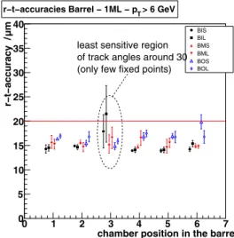
Fig. 7. r(t) accuraciesachievedfor thedifferent typesof barrel chambers usingmuonswithpT>6GeV for thecalibration and separate tracksegments permultilayer. Points denote the chambersof the inner (I),middle(M) and outer (O) layer.
than the claimed r(t) accuracy. For the study, an initial r(t) relation was used with a parabolic deviation from the true r(t). The amplitude of the parabola was chosen to 500 μm.
Testbeam measurements showed, that a typicalstarting r(t) re- lation fromthe integrationmethod differswith asimilarshape but withslightly smaller amplitude fromthe true r(t) relation.
An ensemble test with5 independentsamplesof 2000 tracks perchamber wasperformedto test the algorithm. Fig. 7shows themean accuraciesandthe RMS of the ensemblesformuons with an transversemomentumpT >6GeV of a representative part of all barrel chambers. The slightly worse performance of the inner and middle chambers at position 3 originate from the interval of track angles for these chambers which is spreadaround30◦. Residual based calibrationmethodsare leastsensitive in thisregion of track angles due to thechamber
chamber position in the barrel
0 1 2 3 4 5 6 7
r−t−accuracy / μm
0 5 10 15 20 25 30 35
40 BIS
BIL BMS BML BOS BOL
r−t−accuracies Barrel − 2ML − p >20GeVT
difficult region better performance in
higher accuracies at large angles
Fig. 8. r(t) accuraciesachievedfor thedifferent typesof barrel chambers usingmuonswithpT>20GeV for thecalibration andtracksegmentsover bothmultilayers. Points denote thechambersof the inner (I),middle(M) and outer (O) layer.
687
number of tracks / chamber
0 500 1000 1500 2000 2500
r−t accuracy (μm)
0 10 20 30 40 50 60 70 80
90 p > 6 GeV
p > 20 GeVT T
Fig. 9. Accuracyof the r(t) relation independence of the number of tracks usedfor thecalibration. Themean value of all barrelchambersfor both trigger thresholdsis shown.
geometry. Asthe residualsof trackswith an incident angle of 30◦are perdefinition zero, these tracksprovide no information about the systematical error of the r(t) relation. In addition there are onlytwo fixedpointsin thisangular interval—one of themis shown in fig.5IV. In fig. 8 the accuraciesachievedfor the 20 GeV trigger thresholdare shownusing track segments across both multilayers. Especially in the insensitive region around 30◦ the performance of the method is significantly improved. The accuraciesat larger angels—chamber positions 5 and 6—are slightly better compared to the results using muons with pT > 6 GeV as well. Fig 9 shows the mean accuraciesof all barrelchambersasfunction of the number of trackspercalibration for both trigger thresholds. Only a few hundred tracksare necessary for the method to improve the starting r(t) relationsignificantly. With 1000 tracks, the values are already well below 20 μm and are not improved with a larger number of tracks. The method did not convergeusing lessthan 100 trackspercalibration.
IV. INFLUENCE OF THEMAGNETICFIELD
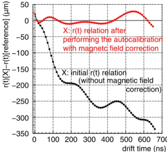
Themagneticfieldalso influencesthe drift path of primary electrons, as the Lorentz force deflects them on their way to the anode wire, leading to longer drift times. As the toroid field is not homogeneous across the MDT chambers, the r(t) relation has to be corrected for the effect of the magnetic field B to reach the necessary precision: in test beam measurements a shift of the maximum drift time of 70 ns/(B2/T2) hasbeen observed[5], [6], leading todeviations ofup to500μmfromthe rt-relation withoutmagneticfield. A model [5], [6] for thedependence of thedrift timet(r, B)asa function of themagneticfield hasbeendevelopedand yields an accuracy of better than 1 ns. The model has been tested withsimulations[4] andwithcosmic muons. Fig.10showsthe difference between the r(t) relation with andwithoutmagnetic field,measured with a MDTchamber in the ATLAS toroidal magneticfield in November 2006 [7]. For both r(t) relations, the autocalibration hasbeen performed, the one gainedwithout magneticfield servesasthe reference r(t) relation. Differences
0 100 200 300 400 500 600 700
−350
−300
−250
−200
−150
−100
−50 50 0
drift time (ns)
r(t)[X]−r(t)[reference] (μm)
X: r(t) relation after
performing the autocalibration with magnetc field correction
X: initial r(t) relation (without magnetic field
correction)
Fig. 10. Differencbetween the the r(t) relationswith andwithoutmagnetic field,measuredin the ATLAS toroidal field. The black lineshowsthechange of the r(t) relationcausedbythemagneticfield. The red curve isthedifference after applying the B-field correction—the r(t) relations diverging less than 20μm.
between the r(t) relations of the order of 300 μm for large drift timesoccur. Applying thecorrection function on thedrift times, thedifferences can be reducedto lessthan 20μm. This first test of themagneticfield correction of thedrift timeswith cosmic muonsin ATLASshowsan excellent performance of themodelled correction function.
V. SUMMARY
The performance of a new approach of autocalibration has beensuccessfullytested withsimulated data. The r(t)calibra- tion of all ATLASmuons chamberswas studied withmuons of two different trigger thresholds and two slightly different approaches to optimize the accuracy of the algorithm. The methodreachesaccuracieswell below 20μmandwill beused as calibration algorithmin the ATLASmuonspectrometer. A model tocorrect the r(t) relation in presence ofmagneticfields hasbeen confirmed with the firstcosmicray data taken with the ATLAS barrel toroidat the nominal field strength.
REFERENCES
[1] ATLAS Muon Collaboration, ATLAS Muon Spectrometer Technical Design Report, CERN/LHCC/97-22, CERN (1997).
[2] M. Deile,Obtaining the Space-Time Relationship of Drift Tubes from the Drift-Time Spectrum, ATLAS note ATL-MUON-99-002,CERN, Geneva, (1999).
[3] M. Deile,Autocalibration: The Influence of the Track Incidence Angles and a New Method, ATLAS note, ATL-MUON-2004-021,CERN, Geneva, (2002).
[4] J. v. Loeben, diploma thesis, Technical University and Max-Planck- Institut f¨ur Physik, Munich, MPI report MPP-2006-241, (2006).
[5] O. Kortner et al., NIMA572,1 (2007),50–52.
[6] C. Valderanis, PhD thesis, Technical UniversityandMax-Planck-Institut f¨ur Physik, Munich, in preparation.
[7] J. v. Loeben, First Cosmic Ray Results of the ATLAS Barrel Muon Spectrometer with MagneticField, paper presentedat this conference.
688
![Fig. 2. Contributions to the transverse momentum resolution of the ATLAS barrel muon spectrometer [1]](https://thumb-eu.123doks.com/thumbv2/1library_info/4007591.1540974/1.918.531.783.623.868/fig-contributions-transverse-momentum-resolution-atlas-barrel-spectrometer.webp)