Integration, Commissioning and Installation of Monitored Drift Tube Chambers for the ATLAS
Barrel Muon Spectrometer
J. Dubberta M. Groha O. Kortnera H. Krohaa J. v. Loebena R. Richtera J. Schmalera H. v. d. Schmitta O. Biebelb D. Merklb
F. Rauscherb A. Staudeb
aMax-Planck-Institut f¨ur Physik, F¨ohringer Ring 6, 80805 M¨unchen, Germany
bLudwig-Maximilians-Universit¨at M¨unchen, Department f¨ur Physik, Am Coulombwall 1, 85748 Garching, Germany
Abstract
The ATLAS experiment at the Large Hadron Collider (LHC) at CERN is currently being assembled to be ready to take data in 2007. Its muon spectrometer is designed to achieve a momentum resolution better than 10% at 1 TeV. In the barrel part, a toroidal air-core magnet is instrumented with three layers of Monitored Drift Tube (MDT) chambers for precision tracking. The Max-Planck-Institut f¨ur Physik and the Ludwig-Maximilians-University in Munich have built 88 MDT chambers for the outermost barrel layer. We report on our experience with the tests of the MDT chambers, their integration with the Resistive Plate trigger chambers and the instal- lation of the muon stations in the experiment. First results of their commissioning in the ATLAS detector will be presented.
Key words: ATLAS, Muon spectrometer, Monitored Drift Tube Chamber, Installation, Commissioning
PACS:29.30.Aj, 29.40.Cs
1 Introduction
The barrel part of the ATLAS muon spectrometer [1] is instrumented with 576 Resistive Plate trigger chambers (RPCs) and 656 Monitored Drift Tube (MDT) chambers as preci- sion tracking detectors in a toroidal field of a superconducting air-core
magnet. The precision chambers are arranged in 3 layers to allow for a measurement of the muon momen- tum from the track sagitta; trigger chambers are mounted on the MDT chambers in the middle and outer layers.
ATLAS MDT chambers [1] consist of two multilayers, each built of 3 or
4 layers of densely packed drift tubes mounted on a support frame; the chamber sizes vary from about 1 m2 to 11 m2 with tube lengths ranging from 1 to 6 m. The drift tubes have a diameter of 30 mm. A single anode wire is stretched in the center of each tube and fixed only at the tube ends with precision endplugs; the sag of the wires in the tubes can be com- pensated by bending the multilayers with respect to the support frame.
The geometry of the MDT cham- bers, as well as their positions in the detector, are continuously monitored by optical alignment systems.
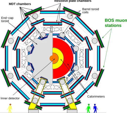
The 88 BOS (Barrel Outer Small) MDT chambers [2] built at the Max- Planck-Institut f¨ur Physik (MPI) in collaboration with the Ludwig- Maximilians-University (LMU) in Munich measure 2.2 m × 4 m × 0.5 m and consist of 432 drift tubes arranged in 2 × 3 layers; they are mounted on the outside of the mag- net coils (cp. fig. 1).
2 Test and Integration of MDT Chambers at CERN
Upon its arrival at CERN, each MDT chamber is subjected to a test programme—leak, high voltage, and noise test—to discover any damage which might have occurred during transport and to guarantee its re- quired performance in the experi- ment.
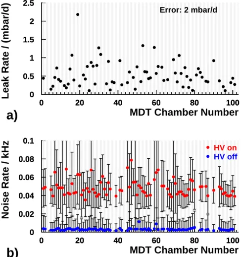
The leak rate of each multilayer is determined from the temperature corrected pressure drop over a time
period of at least 36 h (see fig. 2a).
The high voltage stability at the nominal operating point is tested by measuring the dark current of each tube layer. A noise test is performed without and with HV to differentiate between electronic noise and tubes with internal discharges (see fig. 2b).
At the same time the control inter- face of the front-end electronics is checked as well. The MDT chamber is equipped with B-field and align- ment sensors. All sensors, including the on-chamber temperature probes, are tested. Table 1 summerizes the failure rates of components discov- ered at the home institutes and at CERN, which are below expectation in all areas.
The MDT chamber is then inte- grated with its RPC trigger chamber to form a so-called muon station. The BOS muon stations require a spe- cial common support frame to carry the RPC and the MDT chamber due to their position on the outside of the ATLAS toroid magnet coils. The RPC is inserted in the support frame and the MDT chamber is mounted on three kinematical bearings on top (see fig. 3). The mechanical adjust- ment accuracy is 0.5 mm, fulfilling the requirements on the chamber alignment in the detector. The com- pleted muon station—which weights approx. 1 t—is lifted into a rotator frame to check the adjustment under the angle at which it will be installed in the ATLAS detector (cp. fig. 1).
In the rotator, the MDT multilayers are also bent to follow the gravita- tional sag of the anode wires, which is in the order of 100–200 µm. The precision and repeatability of the sag
adjustment is better than 10µm.
A complete system test of the muon station is performed with cosmic muons. The drift time spectra and pulse height distributions for each tube of the MDT chamber are recorded and the chamber hit profile is measured to allow a check of the correct channel assignment. Similar tests ensure the proper operation of the RPC trigger chamber and the Level 1 trigger electronics.
3 Installation and Commis- sioning of MDT stations in the ATLAS experiment
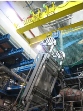
After transporting the muon station to the surface of the ATLAS cav- ern, the functionality of all its com- ponents is tested again. The muon station is then placed into an instal- lation frame and lowered into the un- derground experimental hall. The in- stallation frame is supported by two cranes, rotated to the appropriate angle and docked to the rail system of the ATLAS muon spectrometer, see fig. 4. The muon station is slid onto the rails with the help of two winches and is positioned with an accuracy of 1 mm in all three spatial directions. Installation of the BOS muon stations began in mid Febru- ary 2006 and lasted until the begin- ning of June 2006; a maximum rate of 4 stations per day was reached.
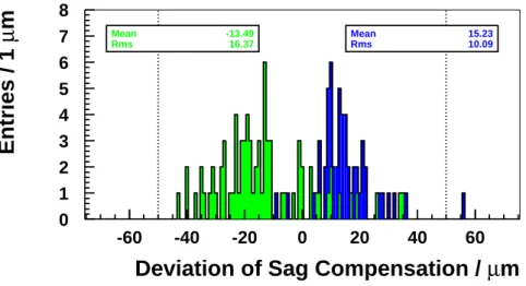
Commissioning of the MDT cham- bers starts immediately after instal- lation: A check of the gas pressure and a high voltage test are performed
and the correct sag adjustment is verified with the on-chamber align- ment system (cp. fig. 5). Chamber- to-chamber alignment systems are checked as well. No failures have been observed after installation.
4 Conclusions
The Max-Planck-Institut f¨ur Physik and the Ludwig-Maximilians-Uni- versity in Munich have built 88 MDT chambers for the ATLAS barrel muon spectrometer. All MDT cham- bers passed the acceptance tests at CERN and were integrated with their RPC trigger chambers. The 88 muon stations were successfully in- stalled in the ATLAS experiment.
After connection of the final services, the stations will be fully commis- sioned with cosmic rays.
References
[1] ATLAS Muon Collaboration, ATLAS Muon Spectrometer Technical
Design Report, CERN/LHCC/97- 22, CERN (1997)
[2] F. Bauer et al., Nucl.Instrum.Meth.
A461(2001) 17-20
F. Bauer et al., IEEE Trans.Nucl.Sci48(2001) 302-307
Component Number
At MPI/LMU At CERN Total
of comp. Percentage
O-Ring Gas seal 289712 0 0 0
Discon. Tube 36192 18 1 0.05
Broken Wire 36192 11 3 0.04
Front-end elx card 4876 50 40 1.85
HV distrib. 88 0 3 3.41
Det. Control Sys. 88 0 4 4.55
T-sensor 1584 2 3 0.32
Alignment comp. 1056 0 3 0.28
B-field sensor 176 0 1 0.57
Table 1
Failure rates of BOS MDT chamber components. Tubes were disconnected due to gas leaks in the endplugs or tubes which exceeded the limit of 1·10-8 mbar L/s.
End−cap toroid
Barrel toroid coils
BOS muon stations
Calorimeters MDT chambers
Resistive plate chambers
Inner detector
Fig. 1. Schematic cross section of the ATLAS detector.
0 0.5 1 1.5 2 2.5
0 20 40 60 80 100
0 0.5 1 1.5 2 2.5
0 20 40 60 80 100
MDT Chamber Number
Leak Rate / (mbar/d)
Error: 2 mbar/d
a)
0 0.02 0.04 0.06 0.08 0.1
0 20 40 60 80 100
0 0.02 0.04 0.06 0.08 0.1
0 20 40 60 80 100
MDT Chamber Number
Noise Rate / kHz
HV on HV off
b)
Fig. 2. Results from the leak rate and noise rate measurement at CERN for all 88 BOS MDT chambers. a) Leak test. The maximum allowed leak rate limit is 7 mbar/d. b) Noise test. The maximum allowed average noise rate is 5 KHz. The error bars are the RMS of the single tube noise distribution.
Common Support Frame with RPC inside
Storage and Transport Feet x
y Drift Tube z
Layers
RPC Trigger Electronics Rail Bearings
MDT Chamber
Fig. 3. Schematic drawing of a BOS muon station.
Fig. 4. Installation of a BOS muon station in the ATLAS detector.
0 1 2 3 4 5 6 7 8
-60 -40 -20 0 20 40 60
Deviation of Sag Compensation / µm
Entries / 1 µm
Rms Mean
16.37 -13.49
Rms Mean
10.09 15.23
Fig. 5. Measurement of the deviation of the sag compensation from its target value of BOS MDT chambers after installation in the ATLAS experiment. The double peak structure is a result of the settling of the adjustment screws during transport, half the stations were transported upside down (dark shade) to simplify their installation in the lower barrel region. The dotted lines show the maximum allowed deviation of 50 µm.