• Keine Ergebnisse gefunden

First experience with the ATLAS Muon Spectrometer

N/A
N/A
Protected

Academic year: 2021

Aktie "First experience with the ATLAS Muon Spectrometer"

Copied!
8
0
0

Wird geladen.... (Jetzt Volltext ansehen)

Volltext

(1)

First experience with the ATLAS Muon Spectrometer

J¨org Dubbert on behalf of the ATLAS Muon Collaboration

Max-Planck-Institut f¨ ur Physik, M¨ unchen, Germany

Abstract

The ATLAS experiment at the Large Hadron Collider (LHC) at CERN is cur- rently being assembled to be ready to take first data in fall 2007. Its muon spec- trometer is designed to achieve a momentum resolution of better than 10% up to transverse muon momenta of 1 TeV. The spectrometer consists of one barrel and two endcap superconducting air-core toroid magnets instrumented with three layers of precision drift chambers as tracking detectors and a dedicated trigger system. We report on our experience with the commissioning and installation of the precision and trigger chambers. First results of the cosmic ray test of the barrel muon spec- trometer with magnetic field are presented, including results of the calibration of the drift chambers and of the spectrometer alignment.

1 Introduction

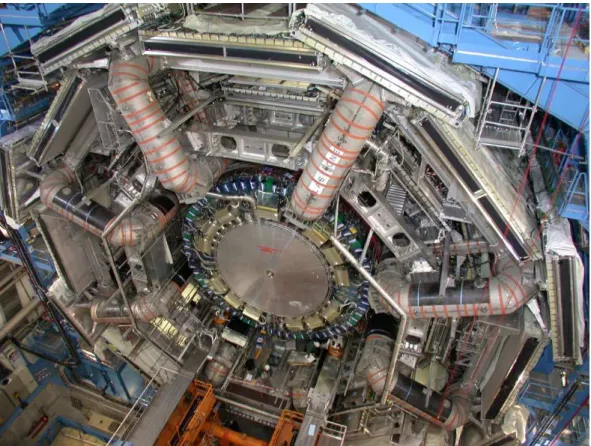
The ATLAS muon spectrometer (see fig. 1) consist of three superconducting air-core toroid magnets instrumented with 1194 precision drift chambers—

Monitored Drift Tube (MDT) chambers, complemented Cathode Strip Cham- bers (CSCs) in the extreme forward region—and 2264 trigger chambers—

Resistive Plate Chambers (RPCs) in the barrel and Thin Gap Chambers (TGCs) in the endcaps [1]. The chambers are arranged in three layers which cover an active area of more than 5500 m 2 up to pseudo-rapidity values of

|η| < 2.7 (trigger chamber coverage extends to |η| < 2.4). Individual chamber sizes vary from 1 m 2 to 11 m 2 . The magnets provide an average field integral of 3 Tm in the barrel and 5 Tm in the endcap region, with a typical path length of 7 m.

The muon spectrometer has been designed for stand-alone operation with a

momentum resolution of 2–3% for transverse momenta below 200 GeV and

better than 10% up to 1 TeV. To achieve the desired momentum resolution,

(2)

Fig. 1. Photograph of the ATLAS detector in February 2007. Visible are the 8 coils of the barrel toroid magnet with 16 sectors of muon chambers installed on them and with the endcap calorimeter inside.

the precision chambers must reconstruct track points with an accuracy of bet- ter than 50 µm, including uncertainties from the misalignment of chambers at distances of 5–13 m. A system of more than 12000 optical sensors continu- ously monitors the deformations of the precision chambers and their relative positions within each layer and from layer to layer and connects them to a ref- erence frame on the toroid coils. The data are used for alignment corrections in the reconstruction with an accuracy of 30 µm in the bending plane.

2 Integration and Installation of the Muon Chambers

Upon their arrival at CERN, all precision and trigger chambers were sub- jected to a extensive test programme, including gas tightness, high voltage stability, and noise tests, to discover any damage which might have occurred during transport and to guarantee the required performance in the experi- ment. These tests supplement the quality control that already took place at the chamber production sites. Alignment and B-field sensors were mounted and tested at CERN, as well as photogrammetric targets for optical surveys.

The barrel toroid magnet has been completed in the ATLAS cavern in Octo-

(3)

Type Channel Dead Perc.

Channel / %

B MDT 184944 123 0.07

B RPC 373344 1726 0.46

EC MDT BW1A+C 147072 61 0.04

EC TGC BW1C 30000 5 0.02

Table 1

Number of dead channels in the barrel (B) and endcap (EC) muon chambers.

ber 2005. To simplify the chamber installation on the magnet coils, the barrel MDT chambers of the middle and outer layers were combined with their RPC trigger chambers to form so called muon stations. The endcap precision and trigger chambers, which are arranged in separate vertical wheel-like structures (6 MDT wheels and 8 TGC wheels) with diameters of up to 25 m, are pre- assembled to sectors. Each wheel consists of 16 (12 for trigger chambers) such sectors.

As a final certification step before installation, the muon stations and sectors undergo a complete system test with cosmic rays, measuring the response and homogeneity of the precision and trigger chambers and the functioning of the on-chamber Level 1 trigger electronics.

In February 2007, all barrel muon stations have been certified and 92% of them are installed in the experiment. The first of eight TGC wheels was assembled in the underground cavern and then released from the wall support structure. A photogrammetric survey of the chamber positions after the movement shows distortions of the wheel structure of only a few millimeters, which do not compromise the detector integrity; the positioning accuracy of the chambers is still satisfactory. The first of six MDT wheels has been assembled as well.

The accuracy of the chamber positions—measured with the internal alignment system during the assembly—meets the required precision, the deviations from the nominal positions have an RMS of 3 mm in the wheel plane and 4.5 mm perpendicular to it. Preliminary tests of the chambers after the installation, gas tightness, high voltage stability and noise test, showed no major problems.

The failure rate of the on-chamber electronics is less than 1%. Table 2 lists the number of dead channels of the precision and trigger chambers discovered up to now.

3 First Cosmic-Ray Measurements with Magnetic Field

A complete system test of the ATLAS barrel muon spectrometer including

precision and trigger chambers, the optical alignment system, the central trig-

ger processor and the data acquisition system took place in November 2006

when the barrel toroid magnet was operated at its nominal field for the first

time. 13 muon stations of the lower barrel region participated in the data tak-

(4)

Fig. 2. Cut-away view of the ATLAS detector, showing only the 13 muon stations participating in the November 2006 cosmic-ray data taking with magnetic field and parts of the barrel toroid. The curved track of a reconstructed muon with about 1.6 GeV momentum is indicated.

ing with cosmic-rays, see. fig. 3. We report preliminary results of the magnetic field measurements, the alignment system, and the MDT chambers. The per- formance of the RPC trigger chambers during the test is described in [2], the Level 1 trigger in [3].

The measurements of the magnetic field with NMR probes in the middle MDT layer agree to better than 0.25% with a linear extrapolation of calculations for half of the field strength. Perturbations of the toroid field at the outer MDT layer caused by the access structures surrounding the detector can reach up to 50 mT. The variations of the perturbations are well simulated, but the model needs further refinement to describe the absolute scale correctly.

The barrel alignment system was used to measure the deformation of the

toroid shape during the magnet operation and the movements of the precision

chambers. The measured deformations of the toroid of a few millimeter at full

field (cp. fig 3) are in agreement with the calculations. Relative movements

of the MDT chambers of up to 500 µm were recorded. Both results underline

(5)

x

y

z Preliminary

14 2

4

16

6

10 8

12

2.0 1.2 0.9

1.2

1.4 1.4

1.2 0.9 1.3 2.0

Fig. 3. Deformation of the barrel toroid magnet at full field (view along the beam axis). The numbers with arrows are in mm.

the importance of the alignment corrections to reach the required precision in the muon momentum measurement.

Fig. 3 shows the angular distribution of positive and negative cosmic muons at the entry of the innermost MDT chmaber layer. It is consistent with the geometry of the two access shafts leading down to the ATLAS cavern with average angles of 10 for the near shaft and -20 for the far one. The rate of muons entering from the far shaft is reduced compared to the ones from the near shaft, as they have to pass approximately 30 m of rock before entering the detector. The muons are clearly separated by the magnetic field according to their charge. The momentum distribution of the cosmic muons is consistent with expectations and the ratio of the number of positive to negative muons,

N µ

+

/N µ

= 1.48 ± 0.27 (prelim.),

(6)

µ + µ

40 80

0

−40

−80 0 1000 2000 3000 4000

Angle of Incidence / Degree

Arbitrary Units

Preliminary

Fig. 4. Angular distribution of cosmic muons measured during cosmic data taking in November 2006.

is in agreement with the PDG value of 1.1–1.4 [4].

To reach the required spatial resolution of 50 µm, the space–drift-time rela-

tion (rt-relation) for the drift tubes of the MDT chambers has to be known

with an accuracy of 20 µm. The rt-relation is determined from the redundant

measurement of the muon tracks in the drift tubes layers of a chamber using

an iterative algorithm called autocalibration [5]. The autocalibration zones,

for which a common rt-relation can be obtained, are in general of the size of

a single MDT chamber to provide a sufficient number and angular spread of

muon tracks necessary for the algorithm to converge. As the toroid field is

not homogeneous over these zones, the rt-relation has to be corrected for the

effect of the magnetic field B to reach the necessary precision: in test beam

measurements [6,7] a shift of the maximum drift time of 70 ns/( B 2 /T 2 ) has

been observed, leading to deviations of up to 500 µm from the rt-relation

without magnetic field. A model [6,7] for the dependence of the drift time t(r)

as a function of the magnetic field has been developed and yields an accuracy

of better than 1 ns. Fig. 3 shows a comparison of the expected change of the

rt-relation and the measurements in the ATLAS toroidal magnetic field as a

(7)

0 2 4 6 8 10 12 14

measurement uncertainty

expected t(r,B>0) − t(r,B=0)

measured t(r,B>0) − t(r,B=0)

0 5 10 15 20 25 30 35

r / mm

t(r,B>0) − t(r,B=0) / ns

Fig. 5. Comparison between the expected (points) and measured (curves) change of the space–drift-time relation as function of the drift radius in an MDT chamber of the middle barrel layer due to the magnetic field. The error bars indicate the variations in the expectation due to the magnetic field variations along the drift tubes.

function of the drift radius, showing an excellent agreement.

4 Summary

The installation of the ATLAS barrel muon spectrometer is almost complete.

All muon station have been assembled and successfully certified. Commission-

ing of the barrel spectrometer with cosmic rays is planned to start in March

2007 and to proceed with a speed of 2 azimuthal sectors per month. The end-

cap spectrometer is well advanced, all muon chambers have been tested and

75% of the sectors are preassembled. Two of fourteen endcap wheels have al-

(8)

ready been installed in the detector. Preliminary test of the barrel and endcap muon chambers, after installation, showed no serious problems. A system test of the barrel muon spectrometer with cosmic rays and the toroid magnet at full field has been performed. The data allows for important studies of the trigger, the calibration and the alignment of the muon spectrometer.

5 Acknowledgments

The author would like to thank all colleagues of the ATLAS Muon Collabora- tion who supplied material for the presentation and the proceedings, especially C. Amelung (CERN), C. Ferretti (University of Michigan), M. Ishino (Univer- sity of Tokyo), O. Kortner (MPI M¨ unchen), W. Kozanecki (Dapnia/Saclay), J. v. Loeben (MPI M¨ unchen), G. Mikenberg (Weizmann Institute of Science), R. Nikolaidou (Dapnia/Saclay), E. v. d. Poel (Nikhef), and S. Zimmermann (CERN).

References

[1] ATLAS Muon Collaboration, ATLAS Muon Spectrometer Technical Design Report, CERN/LHCC/97-22, CERN (1997).

[2] G. Chiodini, paper presented at the conference.

[3] D. Berge et al., paper presented at the conference.

[4] W.-M. Yao et al., J. Phys. G 33,1 (2006).

[5] See e.g. J. v. Loeben, diploma thesis, Technical University and Max-Planck- Institut f¨ ur Physik, Munich, MPI report MPP-2006-241, (2006).

[6] O. Kortner et al., NIM A 572,1 (2007), 50–52.

[7] C. Valderanis, PhD thesis, Technical University and Max-Planck-Institut f¨ ur

Physik, Munich, in preparation.

Abbildung

Fig. 1. Photograph of the ATLAS detector in February 2007. Visible are the 8 coils of the barrel toroid magnet with 16 sectors of muon chambers installed on them and with the endcap calorimeter inside.
Fig. 2. Cut-away view of the ATLAS detector, showing only the 13 muon stations participating in the November 2006 cosmic-ray data taking with magnetic field and parts of the barrel toroid
Fig. 3. Deformation of the barrel toroid magnet at full field (view along the beam axis)
Fig. 4. Angular distribution of cosmic muons measured during cosmic data taking in November 2006.
+2

Referenzen

ÄHNLICHE DOKUMENTE

1) The momentum measurement p middle of the middle chamber is used to determine the rotation of the inner chamber with respect to the outer chamber. The rota- tion angle is

A complete system test of the ATLAS barrel muon spec- trometer including precision and trigger chambers, the optical alignment system, the central trigger processor and the

We studied the segment reconstruction efficiency as a function of the back- ground counting rate and the dead time of the drift-tube read-out with test- beam data which were recorded

For operation at HL-LHC, replacement of the MDT chambers in the barrel inner layer by sMDT chambers with integrated thin-gap RPC chambers is foreseen in order to increase the

The application to cosmic muon data recorded with the top sector of the ATLAS muon spectrometer confirms the accuracy of the alignment corrections provided by the

ˆ The rotation angle between the inner and outer chambers is measured by means of the momentum measurement in the middle chamber, since the mo- mentum measurement of the deection

In the second mode, the L1A signal delivered by the CTPD was used to trigger the readout of the muon detectors and MuCTPI systems, and, in a separate test, the readout of the

The size and number of the calibration regions is a trade-off between conflicting require- ments, such as the statistical and systematic errors, the time spent to collect the data,