Upgrades of the ATLAS Muon Spectrometer with New Small-Diameter Drift Tube Chambers
O. Kortner
a, H. Kroha
a,∗, S. Nowak
a, S. Podkladkin
a, P. Rieck
a, K. Schmidt-Sommerfeld
a, E. Takasugi
a, V. Walbrecht
a, R. Fakhrutdinov
b, A. Kozhin
ba
Max-Planck-Institute for Physics, Munich, Germany
b
Institute for High Energy Physics, Protvino, Russia
Abstract
Small diameter muon drift-tube (sMDT) chambers with 15 mm tube diameter provide excellent spatial resolution like the MDT chambers with 30 mm tube diameter used in the ATLAS muon spectrometer so far, but can be operated at ten times higher back- ground rates and allow for the instrumentation of regions where MDT chambers do not fit in. In April 2014 two BME and in January 2016 another 12 BMG sMDT chambers have been installed in the middle layer of the barrel muon detector and are opera- tional since then in order to increase the acceptance for precision muon momentum measurement using three chamber layers. An unprecedently high sense wire positioning accuracy of 5 µm (rms) has been achieved. In the next long LHC shutdown 2019-2020, 16 BIS 78 sMDT chambers will be installed in the barrel inner layer in the transition region to inner endcap layer to make room for the installation of new RPC muon trigger chambers in order to reduce the accidential trigger rate in this region as required for operation at HL-LHC. This is a pilot project for the complete replacement of the MDT chambers in the small sectors of the barrel inner layer by integrated sMDT-RPC detectors (BIS 1-6) in the ATLAS upgrade for HL-LHC.
Keywords: Muon precision tracking, ATLAS detector, drift-tube detectors, MDT chambers, sMDT chambers PACS: 29.40.Cs, 29.40.Gx
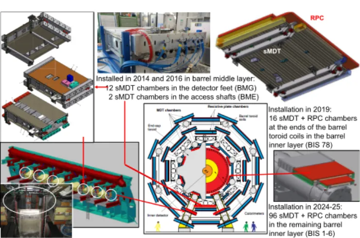
1 sMDT
RPC
Installation in 2019:
16sMDT+ RPC chambers at the ends of the barrel toroidcoils in the barrel inner layer(BIS 78) Installed in 2014 and 2016in barrel middle layer:
12sMDT chambers in the detector feet(BMG)
2 sMDT chambers in the access shafts (BME)
Installation in 2024-25:
96sMDT+ RPC chambers in the remaining barrel inner layer(BIS 1-6)
Figure 1: Overview of the sMDT chambers in the ATLAS muon spectrometer.
1. The sMDT Chambers in ATLAS
An overview of the small-diameter drift tube (sMDT) cham- bers contructed for the ATLAS muon spectrometer is given in Figure 1. The first sMDT chambers [1] have been installed in April 2014 in the barrel middle layer in the access shafts to the calorimeters at the bottom of the detector (BME chambers), followed in January 2016 by the installation of 12 BMG sMDT
∗
Corresponding author
Email address: kroha@mppmu.mpg.de (H. Kroha)
chambers in gaps inside the detector feet in the bottom sec- tors of the barrel middle layer. Both the BME and the BMG chambers improve the muon momentum resolution by a fac- tor of two by allowing for three-point track curvature measure- ment within their geometrical acceptance. Currently 16 BIS 78 sMDT chambers are under construction for installation at the ends of the toroid coils in small sectors of the barrel inner layer in the long LHC shutdown 2019-2020. The chambers will re- place the present BIS 7 and BIS 8 MDT chambers to make space for new thin-gap RPC trigger chambers which will sig- nificantly reduce the accidental muon trigger rate in the tran- sition region 1.0 < |η| < 1.3 between barrel and endcap at HL-LHC. In the ATLAS high-luminosity upgrade 2025-2026, the remaining MDT chambers in the small sectors of the barrel innner layer (BIS 1-6) will be replaced by integrated sMDT- RPC chambers of the same type as the new BIS 78 chambers in order to improve the muon trigger coverage and e ffi ciency in the barrel at the High-Luminosity LHC (HL-LHC) [2].
2. sMDT Chamber Design and Construction
Small-diameter muon drift tube (sMDT) chambers with a tube diameter of 15 mm, i.e. half the diameter of the MDT tubes, have been developed to cope with the higher background irradiation rates at High-Luminosity LHC (HL-LHC) and fu- ture hadron colliders and to fit into the small available spaces available for the upgrades of the ATLAS muon spectrometer.
Preprint submitted to Elsevier June 28, 2018
1 Internal wire locator
External reference surface
Figure 2: Left: Measurement of the sense wire positions of a BMG sMDT chamber with a coordinate measuring machine. The endplug design allowing for precise wire positioning and mechnical measurement is also shown. Right:
Residual distribution of the measured wire positions in a BMG chamber with respect to the nominal wire grid.
Hubert Kroha, MPI Munich ECFA HL-LHC Workshop 06.10.2016 1
Design and assembly procedures optimized for mass production.
Simple, low-cost drift tube design ensuring high reliability.
Industry-standard aluminum tubes (0.4 mm wall thickness).
Sense wire position defined by metal insert alone with high accuracy.
Injection molded endplug and modular gas connector materials selected to prevent outgassing and cracking.
No aging observed up to 9 C/cm charge accumulated on the wire (MDT requirement: 0.6 C/cm).
internal wire locator
external reference surface
Figure 3: Exploded view of an sMDT drift tube. The brass inserts of the in- jection molded pastic endplugs hold the sense wires and define their position in the chamber with few micron accuracy. The gas, signal and ground connections are also shown.
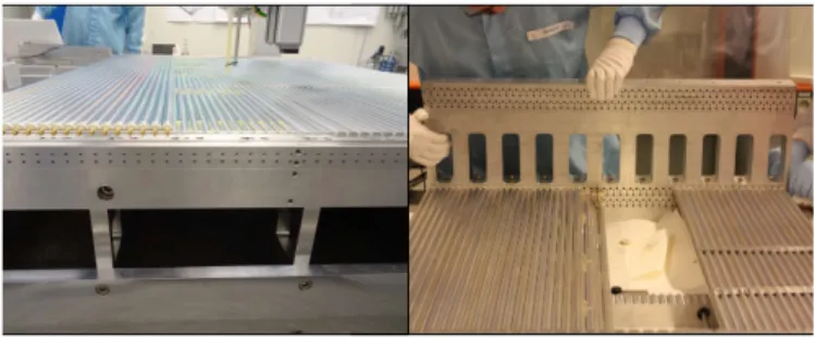
Figure 4: sMDT assembly jigs (left: BIS 78, right: BMG) with precise hole matrix for postioning of the endplug reference surfaces and, therefore, of the sense wires. A multilayer of drift tubes can be completed within one working day. The multilayer distance is alos precisely determined by the jig.
Figure 5: BIS 78 sMDT chamber (left: completed on the assembly table, right:
in the transport frame).
1 3 ASD
chips
TDC chip Encapsulated
coupling capacitor
Hedgehog board
Mezzanine card (24 channels)
Shielding plate Ground pin
Drift tube signal cap