CNIM - 35, rue de Bassano - 75008 Paris - France
Leeds (UK)
Energy-from-Waste plant 160.000t/a Image courtesy of Thomas Graham - Arup
09/2018 - Agence Huitième Jour
A RENEWABLE
SOURCE OF ENERGY Turnkey design & build and services
For:
Household waste
Commercial and industrial waste Biomass
Fuels derived from waste
To produce:
Recyclable materials Compost
Energy (heat and electricity)
Flue Gas T
Integrated Technology for NO
xand Dioxin Removal Inside WtE and Biomass Boilers
Pierre Le Coz and Frank Tabariès
1. Reducing environmental footprint: a stake of the 21st century ...637
2. Pollutant reduction ...638
2.1. Main issues related to NOx reduction ...638
2.2. Usual SCR solution ...640
2.3. Polishing SCR solution and limits ...641
2.4. TERMINOx High Dust Solution ...642
3. Technology back ground ...643
3.1. Enlarging polishing catalyst temperature window ...643
3.2. Improving SNCR / polishing catalyst and T2S efficiencies ...645
3.3. Mastering temperature and fouling ...646
3.4. Decreasing NOx and keeping low NH3 slip ...647
3.5. Thermal/catalyst reduction of dioxin ...647
4. Typical implementation ...648
5. Return of experience ...649
6. Performance summary ...650
6.1. Opex/Capex compared with traditional SCR solutions ...650
6.2. Integrated and advanced solutions ...651
1. Reducing environmental footprint: a stake of the 21st century
In the face of climate change and environmental issues, the continuous improvement of environmental performances of industrial plants is a 21st century strategic challenge.
This major concern applies to the entire energy sector and in particular, the Waste to Energy and Biomass to Energy markets for which we shall consider the importance of exemplary environmental performances. For Waste to Energy, it is required due to their potential location in densely populated areas and the potential suspicion of some citizens, and for Biomass to Energy, the necessarily adequacy between its green image and its environmental performance.
Flue Gas T The necessity of environmental improvement is addressed by the authorities through new and more stringent regulations: a new Best Available Techniques for Large Com- bustion Plants is applicable since July 2017 for Biomass and a new Best Available Techniques for Waste Incineration shall come into force in the coming months.
The new BATs provide new emission ranges, which – in a certain way – prevail and are much more stringent than the emission limit values set by the Integrated Europe- an Directive 2010/75/EU. To be environmentally efficient, it addresses of course new plants, but also older plants, which shall be revamped and upgraded.
In order to anticipate the evolution of the environmental European regulations and to reinforce its leadership in Waste to Energy and Biomass processes, CNIM has developed an efficient and cost effective solution to achieve emissions compliant with the lower range of BAT emission level for NOx and gaseous dioxin called TERMINOx High Dust. By im- proving environmental performance and minimizing capital expenditure and operating cost, this solution contributes to the performance of the Waste and Biomass to Energy facilities and reinforces its complementarity with other energetic sources and sorting.
2. Pollutant reduction
2.1. Main issues related to NO
xreduction
The nitrogen oxides (NOx) are formed by combustion process mainly by oxidation of fuel bound nitrogen compounds called fuel NOx and by oxidation of the nitrogen present in the air at high temperature called Thermal NOx. In the waste incineration field, the majority of the NOx emission comes from fuel NOx which cannot be fully avoided whatever the combustion techniques (air staging, fuel staging) and/or settings are. Consequently, the NOx produced by combustion remains in the range of 250 – 450 mg/Nm3 at 11 % O2 dry, far above the 120 mg/Nm3 required by the BAT.
Therefore, a secondary NOx reduction technique (DeNOx) shall be used. The most commonly applied solution remains the SNCR DeNOx type: Selective Non Catalytic Reduction, where the NOx are chemically reduced by reaction with ammonia. The ammonia comes from an aqueous ammonia solution or by the thermal decomposition of solid or aqueous urea solution.
Pollutant IED
(2010)
BREF WI Final Draft 2018 BAT-AEL
New plant Old plant
NOx (mg/Nm3 at 11% O2) 200 50 – 120 50 – 150
NH3 (mg/Nm3 at 11% O2) – 2–10
PCDD/F I-TEQ (ng/Nm3 at 11% O2) 0.1 < 0.01 – 0.04 < 0.01 – 0.06 PCDD/F + Dioxin like PCBs – < 0.01 – 0.06 < 0.01 – 0.08 Table 1: Applicable emission for waste to energy plants in Europe
Flue Gas T
CO(NH2)2 + H2O → CO2 + 2.NH3 (1)
The following reduction reactions take place in the temperature range of 850 – 1,050 °C
4 NO + 4 NH3 + O2 → 4 N2 + 6 H2O (2)
2 NO2 + 4 NH3 + O2 → 3 N2 + 6 H2O (3)
To avoid NH3 slip at stack, the ammonia is usually dosed at a maximum molecular ratio (β) between 1 and 1.25. Therefore, the NOx reduction reaction is limited between 60 and 70 %.
Considering the range of NOx emission issued from combustion, and the maximum reduction efficiency of SNCR while maintaining the NH3 emission value under BAT value, the lower range of BAT is not reachable with an SNCR. Likewise, reaching the higher range of BAT with an SNCR remains difficult if the fuel NOx produced by combustion are high.
When the SNCR system appears not efficient enough to reach the expected NOx emis- sion, a Selective Catalytic Reduction (SCR) flue gas treatment is applied. The SCR is a proven and efficient DeNOx system. In the SCR, the DeNOx reactions take place with a high efficiency on the surface of the catalyst, at a lower temperature range, around 300 °C. The oxygen atoms required for the DeNOx reactions are directly provided by the Vanadium Pentoxide (V2O5) catalyst. The catalyst recovers this oxygen from the flue gas oxygen content.
4 NO + 4 NH3 + 2.O → 4 N2 + 6 H2O (4)
2 NO2 + 4 NH3 + 2.O → 3 N2 + 6 H2O (5) Figure 1: SNCR conversion ratio
100
80
60
40
20
0 0
20
40
60
80
100
850 900 950 1,000 1,050 1,100 650 750 850 950 1,050 1,150 1,250
temperature °C temperature °C
NH3 slip NH3 oxydation NO reduction NOx prod NOx conversion
% share
%
3.002.75 2.502.25 2.00
1.75 1.50 1.25 1.00 0.75 0.50 0.25
β
β
Flue Gas T
2.2. Usual SCR solution
There are various types of DeNOx SCR implementation.
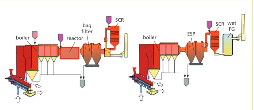
The first category are the tail-end SCRs placed downstream the flue gas treatment and the filtering unit. The tail-end SCRs can be either hot SCRs or cold SCRs.
The hot SCRs operate between 220 and 260 °C depending of SO3 concentration in flue gas. This technology consumes energy to reheat the flue gas at the required temperature using either gas burners or additional steam heaters. Additionally, a large flue gas/flue gas heat exchanger is usually implemented to avoid prohibitive thermal losses.
Alternatively, the cold SCR operates at approx. 190 °C, downstream a sodium bisulphate or a High Specific Surface (HSS) lime dry flue gas treatment. These reagents are onerous and the catalyst requires frequent thermal regeneration (with hot gas generation by gas burners) to eliminate bisulphate and sulphate ammonium salt deposits.
The second category is the in-between SCRs placed upstream the flue gas treatment (usually wet type) and downstream the filtering unit (ESP type). Due to the high sulphur oxide concentration in the flue gas upstream the treatment unit favourable to ammonium salt oxide formation at low temperature, they shall operate with temper- ature above 250 °C. As tail-end SCRs, it requires a flue gas reheating device (burners, steam heat exchanger). Additionally, this technique suffers a risk of dioxin formation in the ESP due to its high operating temperature.
Despite their efficiency on NOx reduction and NH3 slip control, these SCRs suffer the disadvantages of their high capital cost, due to the cost of catalyst and the volume/
complexity of its implementation – which could be a real key issue in the revamping of existing plants – and their impact on the operating cost for the reason given before.
Figure 2: SCR typical arrangements
boiler reactor boiler
tail-end hot SCR arrangement in between SCR arrangement ESP
bag filter
SCR SCR wet
FG
Flue Gas T
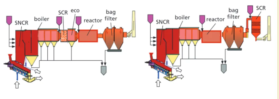
2.3. Polishing SCR solution and limits
A solution consists in adding a SCR at the boiler end in addition to a SNCR system. This solution is called polishing catalyst solution. It could be Hot polishing type when SCR is placed at boiler end to avoid the flue gas reheating device, or a Cold polishing type SCR when placed in tail-end position. For hot polishing catalyst, the implementation and operation in a high pollutant and dusty flue gas atmosphere remains a challenge.
Indeed, depending on the operating conditions (concentration and temperature), the NH3(g) and SO3(g) from flue gas can react either in ammonium sulphate ((NH4)2SO4) or in ammonium bisulphate (NH4HSO4) as shown in figure 4. When this reaction occurs at the catalyst zone, the solid product forms on its surface. This area quickly becomes an impermeable layer to NOx and NH3 molecules poisoning the catalyst. Therefore, its activity decreases very rapidly.
Figure 3: Hot and cold polishing SCR arrangements
bag filter boiler
SNCR reactor
SCR eco
boiler SNCR
bag filter reactor
SCR
To prevent this compound from forming, with the usual SO3 concentrations encoun- tered in the combustion processes and the required NH3 concentrations from the non-catalytic stage to complete the reduction of NOx in the catalytic stage, the catalyst must operate at more than 280 °C.
Figure 4:
Ammonium sulphate and bi- sulphate formation versus NH3/ SO3 content in flue gas
500 100
482 °F 464 °F 446 °F 428 °F
500 °F
10 5 1
1 5 10 50 100 500
(NH3)2SO4
(NH4)HSO4
SO2 concentration ppm NH3 concentration
ppm
50 410 °F
392 °F
Flue Gas T Conversely, at a temperature above 320 °C, molten metallic and chloride alkali salts tend to liquefy and the operation shall be maintained under this temperature range to prevent from catalyst quick fouling.
The temperature window of 280 °C to 320 °C is very restrictive. First in term of plant design: it sets the polishing catalyst in the middle of economizer banks. Secondly, in term of operation: it generates significant difficulties to maintain the SCR short temperature range considering the usual process temperature variations due to boiler fouling along operating cycle. The risk of instantaneous fouling and clogging during cleaning operations of the boiler is also an issue.
2.4. TERMINOx High Dust Solution
The company has developed an innovative solution, fully integrated to the boiler, to address the above-mentioned SCR cost and operational issues. It includes, among other devices a polishing catalyst integrated at the end boilers and applies a patented SO3 management to enlarge significantly the operating windows temperature to avoid catalyst poisoning and a special design to prevent crippling fouling and erosion issues.
The solution is based on a 5-step integrated approach consisting in optimising each step of the NOx formation and reduction with:
1. A primary combustion optimisation including NOx reduction and management of SO3 flue gas content with dolomite patented injection with positive impact on boiler fouling,
2. A secondary combustion implemented and set to maximise the gas residence time and temperature profile in the combustion chamber with positive impact on SNCR+
efficiency,
3. An advanced proprietary SNCR engineering and control system based on local pyrometric temperature measurement with a controlled ammonia slip to supply polishing catalyst with the good ammonia ratio to achieve final NOx reduction, 4. A mastered flue gas temperature at polishing catalyst outlet at (220 °C – 250 °C)
adjusted thanks to a water by-pass control and shock pulse generators to prevent temperature increase by fouling
Figure 5:
Low operating range of SCR
SO3(g) + NH3(g) + H2O(g) NH4HSO4(s) T = f(SO3)
T > 280 °C bisulfate poisoning:
01
(Ca,Na,K,Zn,Pb,Cl,SO4)(l) (Ca,Na,K,Zn,Pb,ClSO4)(s) T < 320 °C
molten salts fouling:
02
Flue Gas T
5. A polishing catalyst size to reduce NOx down to BATAEL level, using the ammonia slip from the SNCR system, with an optimal number of layers to reduce implemen- tation costs and its pressure drop, a pitch compatible with a high dust environment and cleaning device efficiency. Thanks to its wide range of operating temperature, the catalyst can be easily integrated in the boiler allowing significant savings. Figure 6 highlights the main component of the Catalyst section.
Figure 6:
Catalyst stage: general Arran- gement
3. Technology back ground 3.1. Enlarging polishing catalyst temperature window
The purpose is to operate the SCR process in a wider temperature window than the current one (lower level at 280 °C to avoid ammonium bisulphate poisoning and upper level at 320 °C to avoid molten salts fouling) and to ease this integration of the catalyst section in the boiler design for either new or existing plants. Following this principle, the catalyst is ideally located at the end of the economizer banks. Therefore, the oper- ating target temperature is about 220 °C depending on the plant.
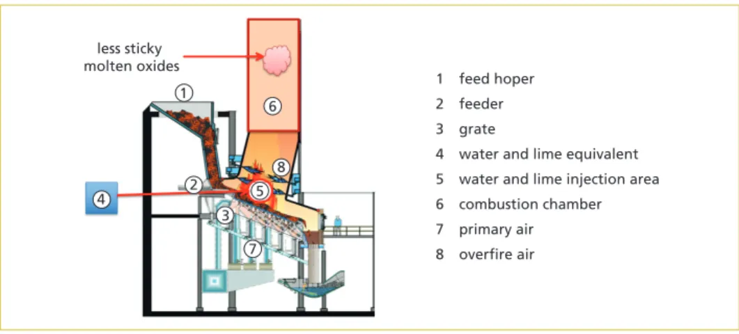
To address this crucial temperature issue, the company has chosen to implement the SO3 management, via an alkaline reagent injection in the furnace, as an efficient solution to operate the SCR at lower flue gas temperature. This reagent, calcium-based sorbent, can be either lime (Ca(OH)2), or dolomite (CaMg(CO3)2) or limestone (CaCO3). The following description focuses on dolomite injection in the furnace, since it is a patent- ed solution. There are three main steps describing this strategy as shown in figure 7.
First, the simplified thermal decomposition in the furnace (temperature greater than 900 °C) can proceed in one step (step 1) leading to porous oxides formation in solid state CaO, MgO and to CO2 formation. Note that the dissociation temperature and the rate of decomposition depend on the proportion of MgCO3 to CaCO3. In addition, the
declogging compressed air tank
by-pass
tangential declogging device catalyst
special pitch by-pass damper
Flue Gas T reagent injection requires a specific window temperature. The upper level is around 1,200 °C to avoid some reactions between solids (silico-aluminates) and dolomite at high temperature. The lower level is around 800 °C to avoid the calcium chloride for- mation with hydrochloric acid or the calcium sulphite formation with sulphur dioxide.
That is why dolomite injection occurs in the primary combustion zone in a very precise combustion zone.
Figure 7:
SO3 management in the furnace via dolomite injection: the three main steps
Figure 8: Dolomite injection on Martin grate-principle
Back to the thermal decomposition of dolomite, the resultant oxide CaO(s), with greater porosities than carbonates, is used in the adsorption reaction with SO3 as described in step 2. The absorption capacity for SO3 increased with increasing temperature. Typically, the temperature range for step 2 is above 900 °C. Indeed, below 850 °C, the following competing reaction consumes CaO(s) to form CaCO3 : CaO + CO2 → CaCO3
Finally, step 3 deals with the reaction between MgO(s) and molten oxides, which are the root cause of exchanger surface fouling. Dealing with dolomite, magnesium carbonate decomposes into magnesium oxide, which actually contributes slightly to the uptake
sticky sticky
01
x.MgO(s) + CaO, SiO2, Al2O3(l) Ca(1-x)MgxO, SiO2, Al2O3(s) reaction with molten oxides:
03 01
CaO(s) + SO3(g) CaSO4(s) SO3 removal:
02
CaCO3, MgCO3(s) CaO(s) + MgO(s) + 2.CO2(g) dolomite thermal decomposition:
01
1 feed hoper 2 feeder 3 grate
4 water and lime equivalent 5 water and lime injection area 6 combustion chamber 7 primary air 8 overfire air less sticky
molten oxides
1 6
5 8 4 2
3 7
Flue Gas T
of SO3 compared to the effect of CaO(s). Nevertheless, this reaction with MgO(s) has an impact on the morphology and the composition of the deposits. It makes the latter more friable, thus ensuring a high cleaning efficiency of the exchanger surfaces by the usual cleaning systems such as soot blowers, shock pulse generators and so on. Keeping clean exchanger surface certainly contributes to improve the control of the flue gas temperatures in the different passes and at boiler outlet.
Thus, dolomite injection helps controlling the flue gas temperatures at the inlet of the catalyst, makes the SCR process temperature window safer, and out of the bisulphate poisoning and the molten salts fouling regions.
3.2. Improving SNCR / polishing catalyst and T2S efficiencies
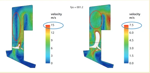
It is essential to ensure a homogenous distribution of the flue gas velocity in the furnace.
Not only this condition relies on under grate air distribution, but it also depends on the secondary air staging, namely the airflow balance between the front and rear walls.
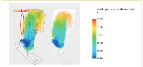
Primary solutions, allowing efficient NOx reduction, require a suitable combustion air staging. Thus, the catalyst solution integrates the following step dedicated to combustion air optimization. A Computational Fluid Dynamics Modelling of the furnace computes the reacting flow in terms of temperature distribution, flue gas and airflow dynamics, and turbulence. Simulations allow finding the optimal design such as the number and the location of secondary air nozzles, as well as the related operating process param- eters. This design complies with the following constraint: simulated particles have a sufficient residence time in the presence of oxygen and sufficiently high temperatures (> 850 °C) in order to achieve high degree of burning (T2S).
The following figures illustrate the case of an existing plant for which CFD simulations determined the optimal configuration in terms of flue gas distribution and DeNOx reagent injection in the furnace.
Figure 9: Overviews of velocity magnitude fields before and after optimization (maxi load case)
15 12 9 6 3 0 velocity m/s
fps = 001.2
7.5 6.0 4.5 3.0 1.5 0.0 velocity m/s
Flue Gas T Figure 9, left side, shows in the initial arrangement a large dead zone, which means a relatively poor mixing in the furnace with a large variation in velocity profile. The right figure shows an optimized configuration that consists in reducing this dead zone and homogenizing the velocities by an optimized secondary air injection.
Figure 10: T2S before and after optimization (maxi load case)
The homogeneity of velocities influences the T2S efficiency and enlarges the SNCR temperature windows. Indeed, with a more homogeneous temperature profile, urea can be injected in a lower range of temperature. This urea will react as follows forming NH3 but also isocyanic acid.
CO(NH2)2 + HCO(NH2)2O → COCO(NH2)2 + 2.NH3 (6) CO(NH2)2 + H2O → NH3 + HCNO (isocyanic acid) (7) The isocyanic acid will fully thermally decompose at the catalyst surface without re- acting previously with chlorine and/or sulphur to form ammonium sulphide/sulphate or chlorides.
HCNO + H2O → NH3 + CO2 (8)
3.3. Mastering temperature and fouling
The catalyst does not require a reheating device. Its temperature window is large and a water bypass on the first ranks of economizers achieves an additional temperature control.
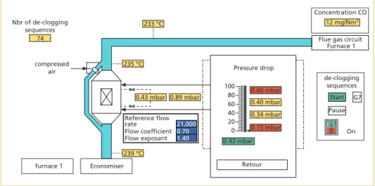
Additionally, the fouling remains under control thanks to:
• The dolomite injection, which slows down the boiler fouling.
• The cleaning devices (shock wave generators type), which contribute to remove less sticky deposits and patented tangential catalyst compressed air de-clogging devices.
2.05 1.66 1.27 0.88 0.49 0.10
track: particle residence time s
Flue Gas T
• The Catalyst partial bypass, which opens during cleaning phases to avoid catalyst bed fouling. During cleaning, bypassed flue gas are treated by the SNCR and mixed with flue gas passing through the polishing catalyst. Due to a higher efficiency of the catalyst at low flow rate, site records show nearly no impact on NOx reduction and only a small and very short increase of NH3 slip.
• Adapted and optimized large catalyst pitch (larger than usual SCR type).
3.4. Decreasing NO
xand keeping low NH
3slip
Half to two thirds of the NOx emissions are reduced by the advanced SNCR. The residual NOx from SNCR reacts with the ammonia slip coming from the SNCR at the catalyst surface to reduce NOx up to 80 – 90 %.
The efficient reactivity of ammonia slip and isocyanic acid on the catalyst ensures the efficiency of the overall DeNOx reactions and enable to maintain the ammonia slip down to 5 mg/Nm3.
An additional NOx reduction (few percent) can be achieved by injecting recovered water. In that case, the water lowers the flame temperature and decreases the thermal NOx emissions.
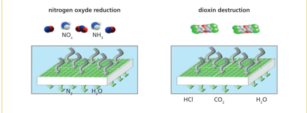
3.5. Thermal/catalyst reduction of dioxin
The catalyst bed ensures also dioxin destruction in gaseous phase.
PCDD: C12HnCl8–nO2 + (9+0,5n)O2→(n–4) H2O + 12 CO2 + (8–n)HCl (9) PCDF: C12HnCl8–nO + (9,5+0,5n) O2 → (n–4) H2O + 12 CO2 + (8–n)HCl (10) The destruction of dioxin in hot zone, before the bag filter, avoids ash contamination by dioxin and ensures compliance with some very stringent local regulations like the Japanese ones.
Figure 11: Nitrogen and dioxin reduction on catalyst
nitrogen oxyde reduction
NOx NH3
N2 H2O
H2O HCl
dioxin destruction
CO2
Flue Gas T
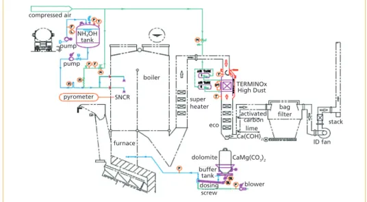
4. Typical implementation
The major components are shown Figure 12. Like the combustion process, all these components have been optimized process wise to maximise their efficiency.
Figure 12: Catalyst – major components
The dolomite is stored in either silos or big bags. The dolomite injection is of dry type with dosing screws, pneumatic conveying lines and pneumatic nozzles, home designed to perform an efficient spray velocity and dispersion.
Ammonia reagent is injected in the advanced SNCR system and will react both at SNCR level and at polishing SCR level, avoiding an additional injection for the SCR.
It can preferably be dry urea injection. This patented solution enables to utilise pure urea, more cost, CO2 and energy effective than liquid urea or ammonia, which are di- luted with water solution respectively at 42 % and 24.5 %. Nevertheless, liquid urea or ammonia can be also applied when local urea market or boiler size makes this choice more efficient.
Due to an efficient NOx reduction at SNCR level, the absence of a reheating unit, re- covery heat exchanger and an optimal Catalyst selection, the volume dedicated to the catalyst remains small enough for an easy implementation in new boilers, but also in revamped boilers, where available space used to be a key issue for SCR implementation.
This low footprint definitely provides to the catalyst a key advantage on other catalyst solutions.
This low footprint also allows, on new plant, to take a provision to integrate later the catalyst to cope with future changes in regulation or to reach low BAT limit later on, if upper-range is already achieved with SCNR.
compressed air
pump
pyrometer SNCR
furnace
lime activated
carbon
blower bag filter TERMINOx High Dust
stack
ID fan
buffer tank dosing
screw dolomite boiler
super heater
eco NH4OH
tank
CaMg(CO3)2 Ca(COH)2 pump
Flue Gas T
5. Return of experience
The return of experience is based on several orders in force and sufficient feedbacks from plants in operation. The hereafter chapter gives main figures on a site in operation for 2 years.
The hereafter feedbacks are based on a Waste to Energy facility in France, equipped with 2 lines, 6 tons/h each, equipped with Martin standard grates (not low NOx type) and CNIM boiler. These 2 lines have been revamped in 2017 to achieve BREF emission values. A catalyst has been implemented to achieve a NOx emission below 80 mg/Nm3 at 11 % O2 and the catalysts have been running continuously for 2 years. The main results are:
• NOx: daily average 70 mg/Nm3 (emission limit: 80)
• NOx: hourly average 80 mg/Nm3 during boiler cleanings (with partial by-pass opens)
• NH3: Daily average 2 to 5 mg/Nm3
(peaks < 15 mg/Nm3 during cleaning phases).
Figure 13:
Typical arrangement of the catalyst
Table 2:
Site emission feedbacks (at 11 % O2)
catalyst
eco
bag filter
• Dioxins: < 0.001 ng/Nm3 Dioxins are treated both by the SCR and the VAPOLAB flue gas treatment.
• Catalyst pressure drop: < 1 mbar after one year of operation and before yearly plant maintenance stoppage.
• Urea consumption: 1,8 to 2,0 kg/ton of waste for NOx at 65 mg/Nm3
CO mg / Nm3 NOx mg / Nm3 NH3 mg / Nm3
Line 1 March 2019 19.40 66.80 4.70
Line 1 April 2019 23.00 66.30 4.30
Line 2 March 2019 22.10 71.70 0.64
Line 2 March 2019 17.30 72.62 0.46
Flue Gas T This urea consumption shall be compared with the 2,0 kg/ton of waste which were consumed before the revamping, but for a 3 times higher NOx emission of 180 mg/Nm3.
Figure 14: Pressure drop < 1 mbar
The operator is fully satisfied with the good performances of the catalyst in terms of achieved emission values in compliance with BREF, its low urea consumptions, its low-pressure drops, and the cost effectiveness of the integrated approach.
6. Performance summary
6.1. Opex/Capex compared with traditional SCR solutions
The returns of experience have demonstrated the ability of the catalyst to achieve the low range of BAT emission for NOx, NH3 and dioxin as per the new BREF requirements, which are not usually reachable with SNCR solutions. Even more, TERMINOx High Dust emission values are comparable with emission levels performed by SCR systems.
In addition, the catalyst has demonstrated its good operability and availability with low-pressure drop and the absence of critical fouling and catalyst poisoning during long runs. Thanks to the 5-step approach and its patented devices, it ad- dresses perfectly the challenge of integrating the hot polishing catalyst in the boiler.
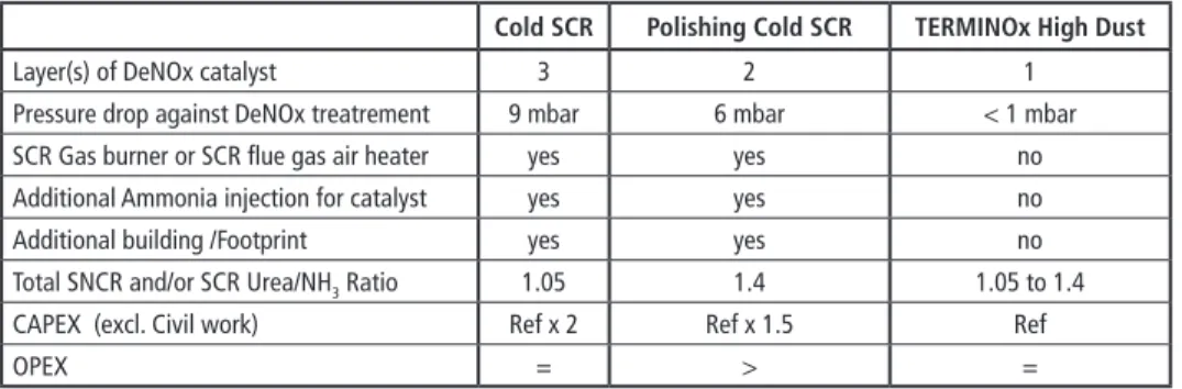
The following table compares, on a real study case, the capital and operational costs related to the implementation of 3 solutions: cold SCR, Polishing SCR and the new catalyst solution to meet the low BAT emission value.
233 °C 74
12 mg/Nm3 Concentration CO
235 °C compressed
air Nbr of de-clogging
sequences
239 °C
0.89 mbar 100
80 0.60 mbar Pressure drop
0.40 mbar 0.34 mbar 0.15 mbar 0.43 mbar
Retour 60 40 20 0
Economiser
21,000 0.70 1.40
furnace 1
Flue gas circuit Furnace 1
de-clogging sequences
Start Pause
On G7
Reference flow rate Flow coefficient Flow exposant
0I 0.43 mbar
Flue Gas T
By significantly saving on catalyst quantity and auxiliaries (flue gas reheating devices, additional ammonia injection…), the new catalyst solution capital investment remains far lower that other conventional DENOx systems.
In term of operation cost, the new catalyst solution is as competitive as an SCR. Its urea/ammonia reagent consumption varies between the stoichiometric ratio of 1.05 (equivalent to an SCR application) up to the stoichiometric ratio of 1.4 (equivalent to an SNCR application) depending of the operation and the catalyst efficiency through- out its lifetime. This slightly higher urea consumption (compared with an SCR) and the dolomite injection costs are fully compensated by a lower electricity consumption due to the significantly lower pressure drop of the new catalyst solution, the benefit of the dolomite on both the boiler cleanness and the lime consumption reduction in the flue gas treatment.
6.2. Integrated and advanced solutions
Thanks to its expertise in boiler and flue gas treatment design, as well as its recognized know-how as Waste and Biomass to Energy EPC contractor, CNIM group is able to innovate and to propose integrated boiler – flue gas treatment solutions offering envi- ronmental and cost effective solutions for client and end-user benefits.
Table 3: Applicable Emission for Waste to Energy Plants in Europe
Cold SCR Polishing Cold SCR TERMINOx High Dust
Layer(s) of DeNOx catalyst 3 2 1
Pressure drop against DeNOx treatrement 9 mbar 6 mbar < 1 mbar
SCR Gas burner or SCR flue gas air heater yes yes no
Additional Ammonia injection for catalyst yes yes no
Additional building /Footprint yes yes no
Total SNCR and/or SCR Urea/NH3 Ratio 1.05 1.4 1.05 to 1.4
CAPEX (excl. Civil work) Ref x 2 Ref x 1.5 Ref
OPEX = > =
Contact Person
Dr. Frank Tabariès CNIM / LAB SA
Environment & Energy Services
Innovation Director and Managing Director Avenue Estienne d'Orves
ZI de Lagoubran 83500 La Seyne Sur Mer FRANCE
+33 494185610
frank.tabaries@cnim.com
Dorfstraße 51
D-16816 Nietwerder-Neuruppin
Phone: +49.3391-45.45-0 • Fax +49.3391-45.45-10 E-Mail: order@vivis.de
TK Verlag GmbH
order now www. .de
Elisabeth Thomé-Kozmiensky
1.5. Generalunternehmer (Planung und Ausführung) Deutsche Babcock Anlagen GmbH
Kesselerneuerung Von Roll Inova, resp. HITACHI Zosen Inova Turbinenerneuerung
1.6. Genehmigungsbehörde Regierung von Oberfranken Ludwigstraße 20 95444 Bayreuth
1.7. Aufsichtsführende Behörde Bayerisches Landesamt für Umweltschutz Bürgermeister Ullrich-Straße 160 86179 Augsburg 1.8. Inbetriebnahme
1978: Linien 1 + 2 und
Klärschlammbehandlung
1981: Linie 3
1982: Erweiterung um Stromerzeugung 1982-1988: Fernwärmeauskopplung und -verteilung 1990: Feuerraumoptimierung, 1. Erweiterung der Abgasreinigungsanlage
1996: 2. Erweiterung der
Abgasreinigungsanlage
Abwasserbehandlung und Schlammentwässerung
Löschwasserbecken Notstrom- aggregate 3+4 Katalysatoren
(SCR)
Gewebefilter Öl-tank
Waage Zentral-lager Grundstücksgrenze
Ausdehnungs- gefäß
Energieteil Abwärmenutzung Heizwerk 1 Abfall- bunker An- lieferung Klärschlamm- Stapelbehälter
Kessel- hausElektro-
filter
Teich Luftkondensator Maschinenhaus für neue Turbine/Generator Wertstoffhof
Stadt Bamberg
Kompostieranlage Kläranlagengelände
AVA Augsburg
3. Abfallaufkommen Abfallarten
Hausmüll: 131.103 t
hausmüllähnlicher Gewerbemüll: 81.835 t
Sperrmüll: 14.204 t
Krankenhausabfälle: 3.363 t
insgesamt: 230.505 t
4. Kapazität, Durchsatz und Geometrie Kapazität (Auslegung) 255.000 t/a davon
• Siedlungsabfälle: 251.500 t/a
• Krankenhausabfälle: 3.500 t/a bei einem Heizwert von 9,2 MJ/kg Durchsatz (Siedlungsabfälle)
Durchsatz 2014: 238.224 t
Durchsatz 2013: 236.693 t
Durchsatz 2012: 233.888 t
Durchsatz (Krankenhausabfälle)
Durchsatz 2014: 3.363 t
Durchsatz 2013: 3.097 t
Durchsatz 2012: 3.257 t
Abmessungen des Baukörpers 235.000 m2
Bauhöhe ohne Kamin: 38 m
5. Anlieferung und Lagerung Abfallanlieferungen mit: LKW
~ 35.000 Anlieferungen/Jahr 5.1. Waage Hersteller:
Bauart: Brückenwaage
Anzahl: 3
5.2. Anlieferungshalle/Entladestation Anzahl der Abkippstellen: 12 5.3. Bunker für feste Abfälle Abfallart: Siedlungsabfälle Maße (l x b x h) 55 m x 13 m x 25 m nutzbares Volumen: 10.000 m3
Nutzmasse: ~ 5.000 t
Anzahl der Abkippstellen: 12 Abfallart: Krankenhausabfälle nutzbares Volumen: 5.000 m3 5.4. Bunker für Schlacken nutzbares Volumen: ~ 500 m3
5.5. Betriebsmittellagerung
Heizöl: ~ 80 m3
Ammoniakwasser: ~ 60 m3
Kalksilo: ~ 50 m3
Bild 5: Schlackehalle der AVA Augsburg
Waste-to-Energy Plants
– Germany –
The actual book 2016|2017 carries forward the survey of waste-to-energy plants in the Federal Republic of Germany which started in the 1990´s. With the first publication we have two books which complement each other perfectly. Both books provide extensive information about the installed technology and the environmental impact of the waste-to-energy plants. The quality of the new inquiry has been extended in terms of the technical data. Existing gaps regarding the data were partially filled.
This is the result from the considerable assistance of numerous plant operators. The publication on hand shall be seen as an interims report. The work on the data acquisition will be continued. For this reason we ask plant operators and manufactures to critically review the release data.
• 33 minucipal solid waste incineration plant
• 7 solid recovered fuel power plant
• 1 Sonderabfallverbrennungsanlage
The further investigations will be extended to the missing German waste-to-energy plants as well as to plants in other countries.
2014 | 2015
ISBN: 978-3-944310-26-8 Hardcover: 581 Pages,
with coloured illustrations Price: 45.00 EUR
2016 | 2017
ISBN: 978-3-944310-38-1 Hardcover: 407 Pages,
with coloured illustrations Price: 68.00 EUR
ABFALLVERBRENNUNGSANLAGEN – Deutschland –
2014 | 2015 Elisabeth Thomé-Kozmiensky
Editor: Elisabeth Thomé-Kozmiensky
ABFALLVERBRENNUNGSANLAGEN – Deutschland –
2016 | 2017 Elisabeth Thomé-Kozmiensky – Deutschland –
– Deutschland – – Deutschland –
Bibliografische Information der Deutschen Nationalbibliothek Die Deutsche Nationalbibliothek verzeichnet diese Publikation in der Deutschen Nationalbibliografie; detaillierte bibliografische Daten sind im Internet über http://dnb.dnb.de abrufbar
Thiel, S.; Thomé-Kozmiensky, E.; Winter, F.; Juchelková, D. (Eds.):
Waste Management, Volume 9 – Waste-to-Energy –
ISBN 978-3-944310-48-0 Thomé-Kozmiensky Verlag GmbH
Copyright: Elisabeth Thomé-Kozmiensky, M.Sc., Dr.-Ing. Stephanie Thiel All rights reserved
Publisher: Thomé-Kozmiensky Verlag GmbH • Neuruppin 2019 Editorial office: Dr.-Ing. Stephanie Thiel, Elisabeth Thomé-Kozmiensky, M.Sc.
Layout: Claudia Naumann-Deppe, Janin Burbott-Seidel, Sarah Pietsch, Ginette Teske, Roland Richter, Cordula Müller, Gabi Spiegel Printing: Universal Medien GmbH, Munich
This work is protected by copyright. The rights founded by this, particularly those of translation, reprinting, lecturing, extraction of illustrations and tables, broadcasting, micro- filming or reproduction by other means and storing in a retrieval system, remain reserved, even for exploitation only of excerpts. Reproduction of this work or of part of this work, also in individual cases, is only permissible within the limits of the legal provisions of the copyright law of the Federal Republic of Germany from 9 September 1965 in the currently valid revision. There is a fundamental duty to pay for this. Infringements are subject to the penal provisions of the copyright law.
The repeating of commonly used names, trade names, goods descriptions etc. in this work does not permit, even without specific mention, the assumption that such names are to be considered free under the terms of the law concerning goods descriptions and trade mark protection and can thus be used by anyone.
Should reference be made in this work, directly or indirectly, to laws, regulations or guide- lines, e.g. DIN, VDI, VDE, VGB, or these are quoted from, then the publisher cannot ac- cept any guarantee for correctness, completeness or currency. It is recommended to refer to the complete regulations or guidelines in their currently valid versions if required for ones own work.