28th International Cosmic Ray Conference
2951
Calibration of the MAGIC Telescope Using Muon Ring Images
M. Shayduk
1, O. Kalekin
1, K. Mase
2,3, and N. Pavel
1for the MAGIC Coll.
(1)Humboldt-Universit¨at zu Berlin, Institut f¨ur Physik, EEP, Newton Str. 14,D- 12489 Berlin, Germany
(2) Max-Planck-Institut f¨ ur Physik (Werner-Heisenberg-Institut), F¨ ohringer Ring6, 80805 M¨ unchen, Germany
(3) Institute for Cosmic Ray Research, University of Tokyo, Kashiwa, Chiba 277- 8582, Japan
Abstract
The new 17m MAGIC telescope will operate at extremely low energy threshold for Air Cherenkov detectors. In order to restore primary spectra, it is necessary to have an absolute light calibration of the telescope camera. A system for such optical calibration is already realized in the MAGIC project.
One can use muon ring images as another possibility to perform the calibration.
Cherenkov light from local muons and gamma-induced showers has the similar spectrum. Parameters of muon (energy, impact parameter, inclination angle) can be obtained from the muon ring image. Using these muon parameters one can calculate the total amount of Cherenkov light in the telescope camera analytically.
Thus, a conversion factor from photons to ADC count can be determined. In this report we present a method of the MAGIC telescope calibration with muon rings.
1. Introduction
The MAGIC telescope was designed to reach the lowest energy threshold of gamma ray detection from the ground level [4,5]. It will permit to detect a big number of gamma rays sources. One of the important tasks for recovering of primary spectra of sources is absolute light calibration of the telescope camera.
A system of that calibration in different wavelengths has been developed by the MAGIC collaboration [2]. An alternative way to perform a calibration is so called calibration by muon rings. This paper is devoted to detailed description of the method developed for MAGIC telescope.
2. Method
Muons, originated from hadronic shower have a broad angular distribution.
Thus, one could record single muon events, when most of the photons hitting the
pp. 2951–2954
c 2003 by Universal Academy Press, Inc.
2952
telescope camera belongs to the only muon. Such events were found out during Monte-Carlo simulations of the hadronic shower and detected in a few experiment (see for example [6]).
If muon track goes through the telescope reflector, the image in camera appears as a ring. Using such images one could restore a single muon track and energy of the incident muon. Afterwards, It reveals a possibility to calculate a total amount of Cherenkov light in camera plane analytically. After that, one could define a conversion factor, measuring the total image size in FADC counts.
In the coordinate frame connected with center of the ring the amplitude distribution along the ring can be written as:
d
2( SIZE
F ADC)
dλdϕ = d
2( SIZE
photons)
dλdϕ · ef f
mirr( λ ) · QE ( λ ) · Conv
phe→F ADC, (1) where λ is the Cherenkov photon wavelength, ϕ - azimuth angle, ef f
mirr- mirror reflectivity, QE - PMT quantum efficiency, and Conv
phe→F ADCis the photoelec- tron to FADC counts conversion factor. This coefficient is hardly simulated and must be extracted from the calibration.
Integrating of the expression (1) over azimuth angle and all wavelengths within the camera sensitivity band gives the following expression for the total image size SIZE
F ADC:
SIZE
F ADC=
2π
0
λmax
λmin
d
2( SIZE
photons)
dλdϕ · ef f
mirr( λ )
·QE ( λ ) · Conv
phe→F ADC· dλdϕ. (2) The integral in the expression (2) can be calculated analytically, using several assumptions. The radius of MAGIC mirror is 17m. The typical Cherenkov angle for muons at the telescope altitude is about 1 . 0
◦. According to this, and assuming for calibration only full ring, one can estimate that the MAGIC camera can ’see’ the light radiated at distances smaller then 1 km from it’s plane. Energy loses of muon in this case are very small and Cherenkov angle can be treated as a constant. The angular radius of MAGIC camera is 2
◦. According to this, full ring can be detected if muon angle with respect to telescope axis does not exceed ∼ 2
◦. For such angles Cherenkov light intensity distortion due to muon inclination is negligible.
Taking into account these assumptions the following expression can be written for the total amount of light in camera:
d
2( SIZE
photons)
dλdϕ =
r(ϕ,Rimp)
0
I ( r ) · r · dr, (3)
where r ( ϕ, R
imp) is the distance between muon impact point and the reflector
edge, R
imp( r ) - muon impact parameter and I(r) - Cherenkov light intensity profile.
2953
Using analytical formula for I(r), SIZE
phe=
α
2 sin 2 θ
c·
λmaxλmin
1
λ
2· Ef f ( λ ) · dλ
· F ( I ) (4) where θ
cis a Cherenkov angle, α is a fine structure constant, r ( ϕ, R
imp) =
R
impcos( ϕ
0− ϕ ) +
( R
2tel− R
2imp) sin
2( ϕ
0− ϕ )
, F ( R
imp) =
02πr ( ϕ, R
imp) dϕ - depends only on muon impact parameter, Ef f ( λ ) - photon conversion efficiency.
Finally, the desired conversion factor Conv
phe→F ADCcan be extracted from:
Conv
phe→F ADC= SIZE
F ADCSIZE
phe(5) where SIZE
phevalues can be delivered from the MC simulations or analytically, according to (4), and SIZE
F ADCcan be measured experimentally as a total image size in FADC units.
As follows from (4), to get the SIZE
phevalues one should know muon impact parameter R
impand Cherenkov angle θ
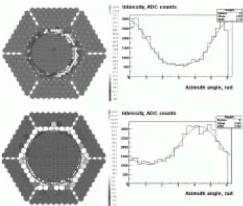
c. These parameters can be restored from the camera image via fitting the circle ( a, b, R ) to the muon ring. Radius R and the center location ( a, b ) was obtained, using maximum likelihood method. It must be mentioned that one should take into account reflector aberrations while fitting. Thus, the fitted circle aspires to the inner part of ring, as can be seen from Fig1. As far as radius R is fitted, Cherenkov angle can be obtained from simple relation theta = R/f , where f is the focus length of MAGIC reflector.
Muon impact parameter R
impappears as a fitting parameter in the expres- sion:
SIZE
F ADCdϕ = Conv
phe→F ADCα
2 sin 2 θ
c·
λmaxλmin
1
λ
2· Ef f ( λ ) · dλ
×
R
impcos( ϕ
0− ϕ ) +
( R
2tel− R
2imp) sin
2( ϕ
0− ϕ ) (6) Intensity histogram dSIZE
F ADC/dϕ was build and fitted using function (6) with fitting parameters R
impand ϕ
0, while Cherenkov angle was treated as a constant, obtained from muon ring approximation. Fitting examples are shown on Fig1.
3. Result and discussion
In present work 8-20GeV muons, originated from 12-15km height with angles 0 − 3
◦, were simulated using CORSIKA Monte-Carlo code [3]. An at- tenuation of the Cherenkov light in the atmosphere was taking into consideration accordingly to CORSIKA’s profile of the atmosphere. Fitting of conversion factor frequency distribution by Gaussian function gave the following value:
Conv
phe→f adc= 4 . 3 ± 0 . 2 dc/phe. (7)
2954
Fig. 1.