28th International Cosmic Ray Conference 2939
The Data Acquisition of the MAGIC Telescope
Florian Goebel,1 Jose Antonio Coarasa1, Ralf Stiehler2 and Sergei Volkov2 for the MAGIC collaboration
(1) Max-Planck-Institut f¨ur Physik F¨ohringer Ring 6, 80805 M¨unchen, Germany (2) Universit¨at-GH Siegen, Walter Flex Str. 3, 57068 Siegen, Germany
Abstract
The data acquisition system of the MAGIC telescope processes the Cheren- kov signals registered in the high resolution camera consisting of 577 PMTs. The analog signals are transmitted via optical fibers to the electronics hut where they are stretched, split into high and low gain channels and digitized with 300 MHz 8 bit Flash ADCs. The digital data is read out by a multiprocessor PC which saves it to a RAID system and a tape library. The system has been designed to process data at a rate of 20 MBytes/sec which is required by the maximum envisaged trigger rate of 1 kHz. Tests of the complete readout chain show that the achieved dynamic range is more than 1000.
1. Introduction
The new generation Cherenkov telescope MAGIC [1,2] is currently in its commissioning phase. A mirror surface of 239 m2 (diameter = 17 m) and a 577 pixel camera will allow one to lower the energy threshold forγ-ray detection down to∼30 GeV which opens a wide physics potential.
The data taking chain consists of fast PMTs collecting the 1-2 nsec FWHM Cherenkov light flashes, 300MHz Flash ADCs for fast sampling, a 2 level trigger system limiting the trigger rate to≤1kHz and a data acquisition system capable to process a data rate of 20 MByte/sec. This system allows effective suppression of the light of night sky and strong rejection of hadron induced air showers while efficiently selecting γ-ray events.
2. Analog signal processing
The PMT signals are amplified by ultrafast and low-noise transimpedance pre-amplifiers in the camera housing. The amplified analog signals are transmitted over 162 m long optical fibers using Vertical Cavity Surface Emitting Laser drivers (VCSELs,λ= 850 nm). In the electronics hut the signal is split. One branch goes to a discriminator with a software adjustable threshold that generates a signal for
pp. 2939–2942 c2003 by Universal Academy Press, Inc.
2940
FADC PMT
577 *
FIFO
optical link
digitization 300 MHz
ring buffer
trigger / eventsamples 30
DAQ PC tape Central Control FADCboard
high gain
switch low gain
delay
PCI 20 MB/s 1 kHz
receiver board
Fig. 1. Schematic overview of the data stream of the MAGIC Telescope
the trigger system. The signal in the second branch is amplified, stretched to ∼6 nsec FWHM and split into a high and a low gain channel in order to increase the dynamic range. The high gain signal is further amplified by a factor 10 while the low gain signal is delayed by 50 nsec. If the signal exceeds a preset threshold the delayed low gain signal is combined with the high gain signal using a fast GaAs switch and digitized by the same FADC.
3. Digital signal processing
The analog signals are continuously digitized with 300 MHz using 8 bit FADCs [3,4,5]. The digitized samples are stored in 32 kByte long ringbuffers.
If a trigger signal arrives within less than 100 µsec the position of the signal in the ringbuffer is determined and for each pixel 15 high gain plus 15 low gain samples are written to a 512 kBytes long FiFo buffer at a maximum rate of 80 MBytes/sec. The readout procedure of the ringbuffer results in a dead time of less than 1 µsec. This corresponds to less than 0.1 % dead time at the design trigger rate of 1kHz. Since the signal has been stretched, the 3.3 nsec time slices will allow for an effective timing resolution below 1 nsec. The time and trigger information for each event is recorded by dedicated digital modules which are read out together with the FADC modules.
The low energy signals from very intense episodic sources like GRB emis- sion or pulsar peaks eventually could exceed the ∼ 1 kHz data taking capability of the DAQ. Therefore a separated high frequency data stream records only the time and trigger information for events triggered by a dedicated high frequency trigger with rates up to 1 MHz.
The complete readout is controlled by a FPGA (Xilinx) Chip on a PCI (MicroEnable) card. The FADC data stored in the FiFo buffers is read out with a rate of 4 Bytes @ 20 MHz. There is one PCI card for each high and low frequency data stream. The multithreaded readout program written in C++ runs on a dual processor Linux PC. The FADC data is reorganized and merged into raw
2941
Fig. 2. Examples of two test pulses of different input charge digitized with the 300 MHz FADCs.
event data format. A fraction of the events is sent to a LabVIEW program which performs the data quality monitoring. The data is saved to a RAID0 disk system at a rate of up to 20 MBytes/sec which amounts to up to 800 GBytes per night.
The readout program is controlled via TCP/IP by the Central Control. During daytime the data is transformed into ROOT format and written to tape.
4. Performance tests
A realistic test of the MAGIC data acquisition system was performed sim- ulating Cherenkov light pulses with a blue LED. The strong, approx. 2 nsec long LED pulses were collected with a ET9116A PMT, which is the 6 dynode bialkali PMT used in the inner sector of the MAGIC camera. The PMT signals were attenuated in steps of 5dB before insertion into a readout chain identical to the one used for the MAGIC telescope including optical transmission over a 1m long fiber. Two Examples of pulses digitized with the 300 MHz FADCs are shown in Fig.2. The low gain signal which is delayed by 50 nsec can clearly be seen for the higher input signal.
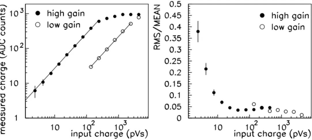
The charge was reconstructed summing the 4 highest consecutive samples after pedestal subtraction. Fig.3.a shows the reconstructed charge Qr for both high and low gain channel as a function of the input charge Qi, where Qi was measured integrating the∼2.8 nsec FWHM wide pulse after the attenuator with a fast oscilloscope. The charge reconstructed using the high gain signal shows a linear behavior as a function ofQi for 2.4 pVs≤Qi ≤200 pVs. For higher values of Qi saturation effects of the 8 bit FADC set in. For Qi ≥150 pVs the low gain signal can be measured which is linear up to ≈ 2000 pVs. Before the low gain signal saturates the FADC at around 4000 pVs small non linearities are observed.
2942
Fig. 3. Left: Reconstructed charge using high and low gain channel versus input charge. Right: RMS/MEAN of the reconstructed charge versus input charge.
They are due to saturation effects in the amplifiers and the optical transmission system.
In Fig.3.b the ratio RMS(Qr)/MEAN(Qr) is shown as a function of Qi. The total dynamic range of the readout system can be defined as Qsat/Q3σ(noise), whereQsatis the input charge for which the low gain signal saturates andQ3σ(noise)
is the input charge for which MEAN(Qr) = 3×RMS(Qr) for the high gain signal.
Thus a dynamic range of the ≥ 4000 pVs / 3 pVs = 1300 is obtained. The HV of the PMTs in the MAGIC camera will be adjusted such that a charge of 3 pVs, for which a signal to noise ratio of 3 is obtained, corresponds to ∼ 1.5 photo electrons.
5. Present Status
The installation and commissioning of the complete readout chain at La Palma is being completed. First calibration pulses have been digitized during tests with 1/6 of the camera. In May-June 2003 we shall be able to record the first Cherenkov flashes with the complete camera and more than 100 m2 reflector area installed.
References
1. ”The MAGIC Telescope” Design Report, MPI-PhE / 98-5 2. M. Martinez for the MAGIC collaboration, these proceedings
3. J. Cortina et al., Procs. Workshop on GeV - TeV Gamma Ray Astrophysics, Snowbird, USA, August 1999
4. R. Stiehler, PhD thesis, Univ. Siegen 2001 5. S. Volkov, PhD thesis, Univ. Siegen 2002