The 28th International Cosmic Ray Conference 1
The Reflecting Surface of the MAGIC Telescope
D. Bastieri,
2C. Bigongiari,
2N. Galante,
3E. Lorenz,
1M. Mariotti,
2R. Mirzoyan,
1A. Moralejo,
2A. Pepato,
2L. Peruzzo,
2A. Saggion,
2V. Scalzotto
2and N. Tonello
1for the MAGIC Collaboration.
(1) Max–Planck–Institut f¨ur Physik, F¨ohringer Ring 6, D–80805 M¨unchen, Ger- many.
(2) Universit`a and INFN Padova, Via Marzolo 8, I–35131 Padova, Italy.
(3) Universit`a di Siena and INFN Sezione di Pisa, Via F. Buonarroti 2, I–56127 Pisa, Italy.
Abstract
The MAGIC Collaboration is starting to operate the ˇ Cerenkov telescope with the largest reflecting surface, in order to lower the energy threshold well below 100 GeV. The MAGIC (Major Atmospheric Gamma Imaging ˇ Cerenkov) Telescope has a 17 m diameter parabolic surface F/1, consisting of 956 spherical aluminium mirrors (50 × 50 cm
2each). In this contribution, we describe the technology adopted to produce metallic mirrors and the methods used to measure the optical quality in terms of: reflectivity, radius of curvature, spot dimension and geometry.
1. Introduction
MAGIC[1] is one of the so-called second generation Cerenkov telescopes ˇ that aims to fill the observational gap between 10 GeV, the upper limit of satellite- borne experiments, and 250 GeV, the lower limit of contemporary ground-based detectors. Lower energy showers emit less ˇ Cerenkov light during their develop- ment in the atmosphere requiring therefore a more sensitive instrument to detect them. This is why it was decided to build a huge reflecting surface (239 m
2) in order to collect as much light as possible.
For the construction of such huge surface, moreover with parabolic shape, the MAGIC collaboration segmented the collecting mirror into 956 smaller ele- ments (50 × 50 cm
2), each machined to spherical shape with the curvature radius that matches better the required overall parabolic shape. The technology ad- opted for the construction of each element (called raw blank ) is borrowed from airplane industry: it consists mainly of using an aluminium honeycomb core to confer the panel lightness and stiffness. More details can be found in sec. 2, while the qualitative description of the produced mirrors will be given in sec. 3.
pp. 1–4 °2003 by Universal Academy Press, Inc. c
2
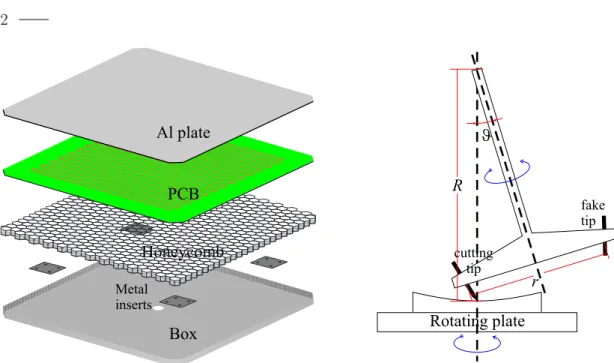
Fig. 1. Exploded view of the raw-blank structure (left ). Sketch of the milling tool and the rotating table (right ).
2. The Mirrors
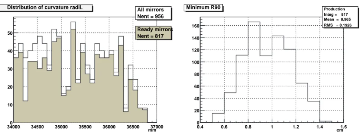
MAGIC mirrors are made of AlMgSi1.0 plates 5 mm thick, machined to spherical shape and polished by diamond milling[2]. Al plates are glued together with an Al-honeycomb inside a thin Al-box and the assembly, called raw blank, weights around 4 kg. The reflecting surface is divided into various zones with different radii of curvature (34.125 ÷ 36.625 m) to match the parabolic shape of the dish. After the diamond milling, front plates are quartz coated against scratches and aging. All the mirrors are grouped onto panels that contain 3 or 4 elements and each panel can be moved and aligned by an active mirror control system. Each mirror is also equipped with a heating system to prevent ice and dew formation.
2.1. Raw blank production
Raw blanks are composed of a 1 mm Al 3003 box, 2.5 cm high, containing the Al 5052 honeycomb of 2.5 cm of thickness and the heating printed circuit board (PCB). Four small plates, 5 mm thick, are embedded into the honeycomb just in contact with the outer box. They will host four screws each, to fix the finished mirror to a panel. The box is then closed with the aluminium plate.
Final assembly of the raw blank parts is done using three layers of 3M glue foils
between box, honeycomb, PCB and front plate (see fig. 1. left). The gluing
procedure consists in a 4-hour cycle, during this time the raw blanks, closed in
an evacuated bag, are heated to 120
◦and stand to 3 atm of pressure. Up to 12
3 mirrors can be made in the same gluing cycle.
2.2. Premilling and diamond polishing
Diamond milling is a lengthy operation: production can somewhat be speeded up by premilling raw blanks to the proper spherical shape. The accuracy of the final premilled shape is better than a tenth of millimetre. The milling is done using an appropriate “T”-shaped tool, a so-called fly-cutter, as shown in fig. 1 (right ). If the raw blank is put onto a rotating plate, the final shape is a spherical surface of radius R according with the formula: R =
sinrϑwhere r is the radius of curvature of the milling tool and ϑ is the angle betweeen the rotating axis of the milling tool and that of the plate.
The diamond milling of the surface is done by the LT Ultra company (Af- tholdelberg, Germany). The geometry of the milling procedure is similar to the one shown in fig. 1. (right ), but with a different set-up and a bigger tool dia- meter. After diamond milling, the roughness of the surface becomes of the order of 10 nm r.m.s. and the overall reflectivity, in the visible, is between 85% and 90%.
The shape accuracy is of the order of the micrometer.
3. Optical quality of the mirrors
A CCD camera (15-bit resolution, linear) free to move along a graduated rail, was used to measure the optical properties of each produced mirrors. The camera is a ST5 from SBIG, cooled and coupled to a 470 ± 10 nm interferometric pass-band filter to reduce stray light and make measurements possible also in the daylight. The optical properties of the mirror, in terms of the size of a LED reflected image, were checked alongside with the measurement of its effective curvature radius.
For the measurement, the light of an ultrabright blue LED (470 nm, 3 mm ∅) is reflected by the mirror under study onto a white screen: the reflected image, the “spot”, is analysed by the CCD camera. The centre of the screen and the LED are at a distance of ∼ 40 cm, and symmetric with respect to the mirror axis.
The distance between the mirror and the LED (and between the mirror and the screen) is twice the focal (or the curvature radius) of the mirror itself, in such a way that a point image is reflected again into a point image. To study the spot evolution around the focal point, a total of 8 ÷ 10 background-subtracted pictures have been taken every 10 cm around the nominal focal position.
Each background-subtracted picture, as downloaded from the camera, con-
sists of a 320 × 240 matrix of values proportional to the light collected in each
pixel. The most important parameter, in our analysis, to be extracted from the
data is the R
90, that is the radius of the circle, taken from the centre of gravity
of the spot, containing 90% of the total, reflected light. As the picture is taken
4
340000 34500 35000 35500 36000 36500 mm37000 10
20 30 40 50
All mirrors Nent = 956 Ready mirrors Nent = 817 Distribution of curvature radii.
0.4 0.6 0.8 1 1.2 1.4 cm1.6
0 20 40 60 80 100 120 140 160
Production Integ = 817 Mean = 0.965 RMS = 0.1926 Minimum R90