The Data Acquisition System of the MAGIC Telescope
J. Cortina
Institut de F´ısica d’Altes Energies, Edifici Cn. Universitat Aut`onoma de Barcelona, 08193 Bellaterra, Spain.
J.A. Coarasa, F. Goebel
Max Planck Institut f¨ur Physik, F¨ohringer Ring 6, 80805 M¨unchen, Germany R. Paoletti, N. Turini
Dipartimento di Fisica, Universit´a di Siena and INFN, sezione di Pisa, Italy R. Stiehler, S. Volkov
Fachbereich Physik, Universit¨at-GH Siegen, Walter Flex Str. 3, 57068 Siegen, Germany
for the MAGIC collaboration.
Abstract
The 17 m diameter Imaging Air Cherenkov Telescope MAGIC [1,2] will be commissioned this year. The extremely fast (∼1-2 nsec) Cherenkov signals registered in the camera PMTs are transmitted in analog form over optical fibers, split into a high and a low gain channel and digitized using 300 MHz 8 bit Flash ADCs [4,5,6]. The digital data produced by the system of 577 FADC channels is read out over one single PCI card by a multiprocessor PC which saves them to a RAID system and a tape library. The system has been designed to record cosmic events with a rate of up to 1 kHz. The 2 level trigger [7] allows to prescale the events and optimize the composition of the recorded data. A parallel acquisition branch allows to record minimal information on events with a much higher trigger rate of up to 1 MHz.
1. Introduction
MAGIC is a new generation Cherenkov telescope [1,2] at the site of the Instituto de Astrof´ısica de Canarias on the La Palma island. A mirror surface of 230 m2 (diameter = 17 m) and a 577 pixel camera allow to lower the energy threshold forγ-ray detection down to∼30 GeV. The lower threshold opens a wide physics potential covering active galactic nuclei, pulsars, supernova remnants, unidentified EGRET sources, γ-ray bursts, cosmology and particles physics.
The data taking chain consists of fast PMTs collecting the 1-2 nsec FWHM pp. 1–9 c2002 by Universal Academy Press, Inc.
FADC PMT
577 *
FIFO
optical link
Central Control
digitization 300 MHz
ring buffer
DAQ PC
tape trigger
1 kHz 30/ eventsamplesFADCboard high gain
switch low gain
delay
PCI 20 MB/s
Fig. 1. Schematic overview of the data stream of the MAGIC Telescope
Cherenkov light flashes from γ-showers, 300MHz Flash ADCs for fast sampling, an efficient 2 level trigger system limiting the trigger rate to ≤1kHz and a data acquisition system capable to process a data rate of 30 MByte/sec. This allows effective suppression of the light of night sky and the electronic noise and efficient rejection of hadron induced air showers.
2. The camera
The camera of the MAGIC telescope consists of 577 PMTs in a hexagonal arrangement of 1.5 m diameter. This corresponds to∼4◦ field of view (FoV). The inner area is equipped with 397 PMTs of type EMI 9116A with a 1 inch diameter.
The outer 180 PMTs are of type EMI 9117A with a 2 inch diameter. In order to increase the light collection area the PMTs are equipped with Winston cone light funnels. The resulting light funnel opening areas of the inner and outer pixels correspond to 0.10◦ and 0.20◦ FoV, respectively. The 6 stage PMTs have semispherical photocathodes with a typical signal response time of 1.0 - 1.2 nsec FWHM. A wavelength-shifter and diffuse scatter coating increases the sensitivity to UV light and the quantum efficiency reaching up to 30 % [3].
250 300 350 400 450 500 550 600 650 700 0
5 10 15 20 25 30
Wavelength (nm.)
QE (%)
ET 9116A type PMT Serial number 1930
- Non-coated PMT - WLS Coated PMT
(transparent lacquer) - WLS Coated PMT
(milky lacquer)
Fig. 2. The quantum efficiency of the EMI 9116A type PMTs with and without coating as a function of the wavelength.
3. Analog signal processing
In the camera housing the PMT signals are amplified by ultrafast and low- noise transimpedance pre-amplifiers. The amplified analog signals are transmitted over 162 m long optical fibers using Vertical Cavity Surface Emitting LASERs (VCSELs,λ = 850 nm). In the electronics hut the signal is split. One branch goes to a discriminator with a software adjustable threshold that generates a signal for the trigger system. The signal in the second branch is amplified, stretched to 6 nsec FWHM and split into a high and a low gain channel in order to increase the dynamic range to more than 1000. The high gain signal is further amplified by a factor 20 while the low gain signal is delayed by 50 nsec. If the signal is above a preset threshold the delayed low gain signal is combined with the high gain signal
4. Digital signal processing
The analog signals are continuously digitized with 300 MHz using 8 bit FADCs [4,5,6]. The digitized samples are stored in 32 kByte long ringbuffers.
When a trigger signal arrives within 100 µsec the position of the signal in the ringbuffer is determined and for each pixel 15 high gain plus 15 low gain samples are written to a 512 kBytes long FiFo buffer at a maximum rate of 80 MBytes / sec. The readout procedure of the ringbuffer results in a dead time of less than 1 µsec. This corresponds to less than 0.1 % dead time at the design trigger rate of 1kHz. Since the signal has been stretched, the 3.3 nsec time slices will allow for an effective timing resolution below 1 nsec.
The FADCs for the 577 pixels are contained in 4 racks with 5 crates. Each crate contains 4 motherboards equipped with 8 FADC cards each. The data is multiplexed and send to one PC by a hierarchical structure of interface boards.
The time and trigger information for each event is recorded by dedicated digital modules which are read out together with the FADC modules.
The signals from very low energy of very intense episodic sources like GRB emission, pulsar peaks etc. exceed the ∼ 1 kHz data taking capability of the DAQ. Therefore a separated high frequency data stream records only the time and trigger information for events triggered by a dedicated high frequency trigger with rates up to 1 MHz.
5. Data processing
The complete readout is controlled by a FPGA (Xilinx) Chip on a PCI (MicroEnable) card. The FADC data stored in the FiFo buffers is read out with a rate of 4 Bytes @ 20 MHz. There is one PCI card for each high and low frequency data stream. The multithreaded readout program written in C++ runs on a dual processor Linux PC. The FADC data is reorganized and merged into raw event data format. A fraction of the events is sent to a LabVIEW program which performs the data quality monitoring. The data is saved to a RAID0 disk system at a rate of up to 20 MBytes / sec which amounts to up to 800 GBytes per night.
The readout program is controlled via TCP/IP by the Central Control. During daytime the data is transformed into ROOT format and written to tape.
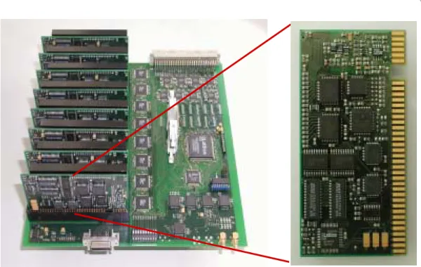
Fig. 3. Left: A photo of a mother board equipped with 8 FADC cards. Right: A closer photo of a FADC card.
6. Trigger system
The trigger of the MAGIC telescope [7] is split into 2 stages. The level 1 triggers on fast simple coincidence patterns while the level 2 performs slower but more sophisticated pattern recognition. The input to the first level trigger (L1) is generated by a discriminator in each of the 325 inner camera pixels. The threshold of the discriminators can be set to a given number of photo electrons.
The L1 searches for clusters of n next neighbor clusters in 2-5 nsec coinci- dence windows of n = 2, 3, 4 and 5 pixels. The input rate per pixel of ∼1 MHz is reduced to a L1 output rate in the order of 1 kHz. The L1 is implemented with programmable logic devices.
The second level trigger (L2) uses VME SMART modules. It analyzes the digital images using look up tables and provides rough estimates for the center of gravity and the energy of events. It allows to mask bright stars and to operate the telescope during moon shine. Depending on the event characteristics the L2 produces different trigger types.
The output of the L2 is processed by a unit which prescales each trigger type independently in order to optimize the composition of the recorded data and to reduce the trigger rate to less than 1kHz for the low frequency data stream and
cosmic events during calibration and pedestal runs.
7. References
1. ”The MAGIC Telescope” Design Report, MPI-PhE / 98-5 2. E. Lorenz, these proceedings
3. D. Paneque et al., Procs. Workshop on New Developments in Photon Detection, Beaune, France, June 2002
4. J. Cortina et al., Procs. Workshop on GeV - TeV Gamma Ray Astrophysics, Snowbird, USA, August 1999
5. R. Stiehler, PhD thesis, Univ. Siegen 2002 6. S. Volkov, PhD thesis, Univ. Siegen 2002 7. D. Bastieri et al., NIM A 461, p. 521, 2001