Muon Detector-Description as-built and its Simulation for the ATLAS Experiment
D. Rebuzzi, N. Ch. Benekos, S. Baranov, L. Chevalier, S. Goldfarb, J.-F. Laporte, T. Moore, A. Ouraou, D. Pomarede, M. Schott, S. Spagnolo, I. Trigger
Abstract— The ATLAS detector at CERN is designed to fully exploit the physics potential of the LHC by providing preci- sion measurements of the mass and identification of particles emerging from high-energy proton-proton collisions. The ATLAS Muon Spectrometer is a large and complex system, comprising Monitored Drift Tubes (MDT), Cathode Strip Chambers (CSC), Resistive Plate Chambers (RPC), and Thin Gap Chambers (TGC).
These systems are described in the software using a set of geometrical primitives, called GeoModel, which constructs a transient model from primary parameters, called AMDB, stored in the detector description database. The model provides a single interface to the GEANT4 simulation, event reconstruction, and trigger software.
In the present note we describe the current status of the ATLAS Muon Spectrometer simulation, the geometry software, placing an emphasis on the achievement of realistic effects recently implemented to take into account the detector as-built.
A first evaluation of as-built geometry in the simulation on the Spectrometer performance and on the physics observable is also discussed.
Index Terms— ATLAS MuonSpectrometer, GEANT4 Simulation, as-built detector description, MuonGeoModel.
November 9, 2006 I. INTRODUCTION
The ATLAS detector [1], currently being installed at CERN, is designed to make precise measurements of 14 TeV proton- proton collisions at the Large Hadron Collider (LHC), starting in 2007. The apparatus, one of the biggest and most complex ever designed, requires a detailed Detector Description and flexible Simulation to deal with questions related to design optimization and to issues raised by staging scenarios, enabling detailed physics studies which will lay the basis for the first physics discoveries.
The full simulation of the ATLAS detector [2] consists of a collection of independent modules developed by the different teams of each subdetector (Inner Tracker, Calorimeters, Muon Spectrometer and Magnet System). Dynamic loading and the organization of the detector simulation in the form of plug- in modules makes the implementation extremely simple, as no modification of the framework code is required. These systems are described in the software using a set of geometry primitives, called GeoModel, which constructs a transient model from primary parameters stored in the detector description database.
The reference simulation tool adopted by all the detector com- ponent applications is the GEANT4 package [3]. It deals with
Manuscript received ; revised . This work was supported by the IEEE.
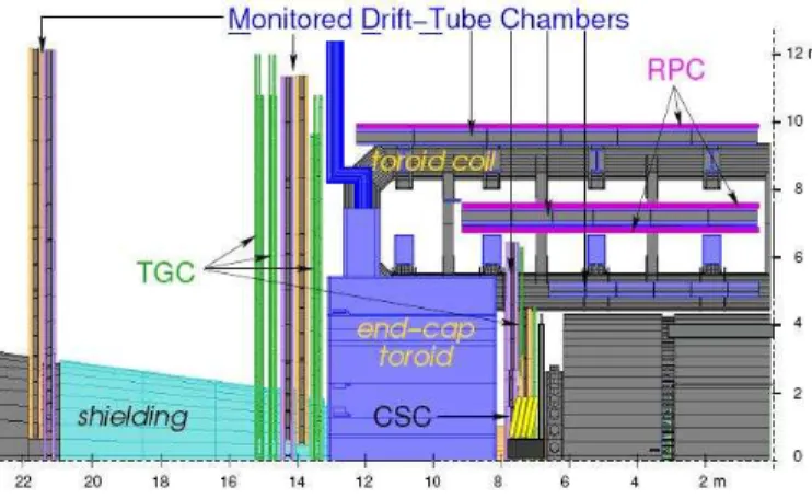
Fig. 1. A section in the r−z plane of a sector of the ATLAS Muon Spectrometer. All the four technologies which compose it are shown, together with the endcap and barrel toroids.
the new physics environment, testing the apparatus prototypes extensively, using real data from the ATLAS Combined Test- Beam (CTB).
II. ATLAS MUONSPECTROMETERBASICSTRATEGY
The LHC will provide many physics channels with muonic final states, as H → ZZ⋆ → 4l, H → ZZ→4l, Z′ → µµ, W′ → µν, etc.. Good muon identification and reconstruction is extremely important for the physics at LHC. The ATLAS Muon Spectrometer [4] is designed to provide good muon identification and reconstruction, a precise measurement of the muon momentum, providing information to be matched for association with the Inner Detector. It also triggers on single and multi-muon event topologies, unambiguously associating any muon with its parent bunch crossing.
The Muon Spectrometer has been designed to provide a three-point measurement of tracks in large superconducting air- core toroid magnets. Its momentum measurement capability combines the highest possible efficiency with a momentum resolution of 2-3% at 10-100 GeV/c and 10% at 1 TeV, taking into account the high-level background environment, the inhomogeneous magnetic field, and the large size of the apparatus (24 m diameter by 44 m length). An optical alignment system controls the relative positioning of muon chambers at the 30 µm level. Figure 1 shows a section of the ATLAS Muon Spectrometer in the r−z plane. All the Spectrometer components are visible.
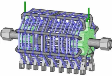
Fig. 2. Simulated Muon Spectrometer. Not only the active part of the detector are included in the MuonGeoModel classes, but also the dead material components (Toroids, Endcaps, Feet, Rails, etc.) and the material descriptions.
III. ATLAS MUONSPECTROMETERDETECTOR
DESCRIPTION
The Muon Detector Description is one of the primary con- cerns for such a complex detector, focused on the implemen- tation of an optimal desciption as well as on the development of the global design. A new ATLAS-wide Detector Description software package, GeoModel, has been fully deployed in the Muon System as the single source of geometry information for both the simulation, the digitization and the reconstruction.
MuonGeoModel [5], the implementation for the Muon Spec- trometer in GeoModel, provides a scheme for accessing both the raw geometry of a detector and subsystem-specific services synchronized to the raw geometry, while incorporating time- dependent alignments. The toolkit is optimized for minimum memory consumption.
This geometry implementation is able to run on various layouts. The ATLAS Muon DataBase (AMDB) [6] ASCII file is the primary source for the layout geometry parameters, which derive directly from the techical drawings. An Oracle Detector Description Database is the unified source of the AMDB parameters for the MuonGeoModel package. A precise description of the passive materials, including shields and toroidal magnet systems, has also been implemented to account for the multiple Coulomb scattering and for the energy losses.
The MuonGeoModel interface to the Muon Spectrometer Simulation is provided by the Geo2G4 conversion of the GeoModel geometry to the GEANT4 format.
As the effective operation of the detector relies strongly on the correct alignment of its precision elements, the model is further required to accurately describe the relevant chamber misalignments and deformations.
IV. ATLAS MUONSPECTROMETERSIMULATION
A. From Generated Event to Muon Hits
The Muon Simulation program models the response of several detector technologies. It comprises five different subsys-
Fig. 3. Simulation Identifier contents and Muon Hit objects for the four Muon technologies. The first threee fields of the SimID specify the name of the station where the hit is located and its (η,φ) position. The remaining fields give information about the specific sensitive volume in which the hit occurred.
Besides the SimID, the Muon Hits contain additional information, listed here, which is required by the digitization and the pile-up procedures.
tems: two for the precision chamber description (MDT, CSC), two for the trigger system (RPC, TGC) and the toroids, which support many of the chambers and provide the magnetic field.
During the Muon Simulation, GEANT4 tracks the particles coming from the particle generator and each time they intersect a Muon sensitive volume, it creates a Muon hit. Hits are the snapshots of the track interactions in the sensitive parts of the Muon detector. A given volume described in the Muon- GeoModel geometry becomes sensitive when associated to a properly implemented Sensitive Detector, which is an instance of a class different from the one describing the real tracking geometry.
The GEANT4 hits are collected using AthenaHitsVector con- tainers, one for each Muon technology, where they are inserted in a random way (no sorting is performed at the simulation level). There are therefore four independent hit collections in the Muon Spectrometer per event, one for each technology.
Muon hits are labeled by a Simulation Identifiers, a 32-bit integer in which the information about the hit position in the Muon System global coordinated is stored. In addition to the Simulation Identifiers, each Muon Hit contains the quantity to be digitized. The Hits have a very light content, most of the information being encapsulated into the Simulation Identifier.
Figure 3 lists the content of the Simulation Identifiers and the Muon Hits for all the four Muon technologies.
B. From Muon Hits to Muon Digits: the Muon Digitization The Muon Digitization is the simulation of the detector response, it converts the Muon Hits into Raw Data Objects, or the electronic output of the Muon Spectrometer . It has been recently completely re-written [7] to cope with the GEANT4 simulation.
The digitization process consists of three steps: in first, hits from different bunch crossing are merged together. Hits are overlaid taking into account their global time, which is defined as the GEANT4 hit time plus the bunch crossing time with respect to the main crossing. Simulated GEANT4 hits persistified (using POOL) can be read in together with previously generated minimum bias and cavern background
Fig. 4. Contents of the Offline Identifiers (OIDs), of the Muon digit objects and of the Muon RDOs for each Muon technology. The first four fields of the OID specify the name of the station where the Digit is located, its (η,φ) position and the technology type. The remaining fields give information about the specific sensitive volume in which the digit occurred. Muon digits contain the OID plus additional information, listed here, required by the reconstruction. For the CSC, the numberNof ADC samplings may be variable; however the default isN= 4.
events. The hit overlay and sorting according to the given detector elements is then carried out as described above, and the digitization proceeds afterwards. In the following step, the output of the detector simulation is converted to Muon Digits.
In the third and last step, the Muon Digits are converted to RDO from which the byte stream (the electronic output) is obtained.
The Muon Digits are objects that can be fed directly in the Muon Reconstruction for debugging and validation purposes.
They are the output of the second step of the digitization procedure, resemble the detector output and are basically de- fined by the reconstruction group. Muon Digits are labeled by an offline identifier (OID) which create the connection to the reconstruction. The OIDs in principle do not coincide with the Simulation Identifiers associated to the hit objects. The design idea is to keep the event simulation disentangled from the digitization/reconstruction. In Figure 4, the contents of the OIDs, of the Muon Digits and of the RDOs are shown for the four Muon technologies.
Any reference to the Monte Carlo information is lost after the digitization, that is, the Muon Digits or the RDOs do not carry any link (pointer, associations) to the original simulated particles. However, such “links” are necessary to establish the Monte Carlo truth tracks and for validation purposes.
During the Muon Digitization, a separate object is recorded and can be persistified, to maintain the link to the original simulated particles at the digit or RDO level. The recorded object in question is a map of muon off-line identifiers to MuonSimData objects. This procedure is not applicable to the real production running. However, MuonSimData objects can be made persistent in the simulation of non pile-up situations and are useful to carry the associations to the original particles to the tracking stage.
V. MUONSPECTROMETERAS-BUILTSIMULATION
The last computing data challenge phases, (”DC2” or
”Rome”), completely performed in the GEANT4 environment, proved the robustness and the stability of the whole simulation apparatus on a large quantity of generated event samples (single
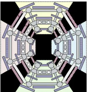
Fig. 5. Transverse section of the MuonSpectrometer with the “egg-shape”
deformation.
particle, B scans and Higgs) as well as on high statistics single particle, minimum-bias events, QCD-jets and physics event productions [8]. As the effective operation of the detector relies strongly on the correct alignment of its precision elements, the model is further required to accurately describe the relevant chamber misalignments and deformations. The current Data Challenge Phase 3 (or Computing System Commissioning) is focused on the simulation of a realistic misaligned geometry, as it is built.
Different realistic effects have been included into the sim- ulation of the MuonSpectrometer, at different levels. Several layouts are available, the misalignment parameters are stored in the geometry/conditions database. For instance, to take into account the deformation of the Muon Spectrometer due to the chamber weight and to the magnetic field deformating effect, a database in which the Spectrometer has an “egg- shape” transversal section has been evaluated (deformation is of the order of 7 mm maximum), as shown in Figure 5 (the deformation is not on real scale, it is magnificated by several factors).
As the Spectrometer performance is enhanced by the align- ment of its precision chambers, the incorporation of time- dependent misalignments and deformations of chambers is an important aspect of the realistic Detector Description. Six parameters per chamber are used to describe translations and rotations with respect to the nominal positions, or a random shift and tilt of the muon chambers with respect to the nominal positions can be included, to take into account possible mis- alignment effects. These gaussian random misplacements have width equal to 1 mm and 1 mrad respectively, by default, but they can be modified to magnify or reduce the misalignment effect. The deformations could also be accounted for by the global temperature expansion and eight additional parameters (torsion, cross plate sags and elongations (RO/HV), long-beam
Fig. 6.
sags, trapezoid effect).
At the digitization level the effect of the sagitta of the wires in the MDT tubes can be also taken into account. The wire sagitta has a geometrical effect, modifying the wire position inside the tube, and can cause an electrostating deflection: altering the axial symmetry modifies the electric field and the maximum electron drift path. Therefore the resulting r-t relation of the drift tube is distorced.
Tho take into account the full background to physics events at LHC, the signal is piled-up with mininum bias events, which occur simultaneously with the hard processes, and with hits from background particles in the experimental hall, through the procedure described in Section IV-B. These background parti- cles, referred as cavern background, are due to the interactions of hadrons produced in theppcollisions with the shielding, the forward detectors, the collimators, etc. They behave like a gas of neutral and charged particles which diffuses throughout the cavern and through the apparatus with no time correlation with the bunch collisions, inducing high detector counting rates.
A. Impact on Physics
The effect of the chamber misalignment on the Muon Spec- trometer performance can be evaluated by using a misaligned database to reconstruct muon tracks simulated with the nominal geometry.
The effect on the transverse momentum resolution is shown in Figure 6, where the difference between the reconstructedpT and the one from the Truth is plotted (in pT-Truth unit). The solid histogram refers to the perfect layout, while the shaded one correspond to the misaligned one (at the reconstruction level). The resolution scales linearly with the misaligned pa- rameter, as shown in Figure 7. The effect of the misalignemt on the muon reconstruction efficiency and on the rate of fake muons, is instead negligible. These studies have been performed using single muons with fixed momentum.
Fig. 7.
Fig. 8.
The effect of the misalignment on theZmass resolution can be eveluated from Figure 9 in comparison to Figure 8, in which the nominal layout is used also at the reconstruction level. There is a clear effect of the random misalignment on the width of theZ boson resonance, at the level of 20%.
Studies on the effect of the sagitta corrections on the physics observable are ongoing. Under accurate evaluation is also the impact of the full pileup on the muon reconstruction efficiency.
VI. CONCLUSION
We presented a review of the status of the simulation of the Muon System, starting from an analysis of the program design for the different components of the Spectrometer, describing all the applications implemented (such as Detector Description, Detector Simulation and Digitization, recently re-written to cope with the GEANT4 simulation input).
Given the complexity of the geometry and the need for a high degree of precision in most measurements, an important empha- sis has been put in the implementation of an as-built description of the MuonSpectrometer. The impact of the realistic effects on the spectrometer performance and on the physics observables
Fig. 9.
has been disucssed. Many studies are currently ongoing, aiming at evaluating also the impact of the full pileup scenario on the physics analysis results.
A variety of methods are employed to validate the ideal and misaligned descriptions, including visualization based on Open Inventor and its HEPVis extensions, and statistical tests based on the large-scale Monte Carlo massive production of the ATLAS Data Challenges. The Muon Spectrometer Detector De- scription system has also undergone extensive visual debugging also in the past year, and experience with the new system has been gained not only though Data Challenges but also through the Combined Test Beam and Commissioning phase.
REFERENCES
[1] ATLAS Collaboration, “Muon Spectrometer Technical Design Report”, CERN/LHCC/97-22 (1997).
[2] A. Rimoldi, A. Dell’Acqua, M. Gallas, A. Nairz, J. Boudreau, V. Tsulaia, D. Costanzo, “The Simulation of the ATLAS EXperiment: present Status and Outlook”, ATL-SOFT-2004-006, CERN, 15 Nov 2004.
[3] A. Agostinelli et al., “GEANT4 - a simulation toolkit”, Nucl. Inst. Meth.
A 506 (2003), 250-303.
[4] ATLAS Muon Collaboration, “Muon Spectrometer Technical Design Re- port”, CERN/LHCC 97-22, June 2002.
[5] S. Spagnolo et al., “The Description of the Atlas Detector”, Proceedings of CHEP04, Interlaken, Switzerland, 27 Sep. - 1 Oct. 2004.
[6] AMDB Web Page,http://atlas.web.cern.ch/Atlas/GROUPS/
MUON/AMDB SIMREC/amdb simrec.h tml
[7] D. Rebuzzi, K. A. Assamagan, A. Di Simone, N. Van Eldik, Y. Hasegawa,
“GEANT4 Muon Digitization in the ATHENAFRAMEWORK”, ATLAS- COM-MUON-2006-003.
[8] D. Costanzo, A. Dell’Acqua, M. Gallas, A. Nairz, N. Benekos, A. Rimoldi, J. Boudreau, V. Tsulaia “Validation of the GEANT4-Based Full Simulation Program for the ATLAS Detector”, ATL-SOFT-PUB-2005-004.