Tube Chambers
Sebastian Nowak ∗† a , Sergey Abovyan a , Varuzhan Danielyan a , David Fink a , Markus Fras a , Vazgen Gabrielyan a , Oliver Kortner a , Hubert Kroha a , Sebastian Ott a , Robert Richter a , Philipp Schwegler a
a Max-Planck-Institut für Physik, Munich on behalf of the ATLAS Muon Collaboration
The ATLAS Muon Trigger in the ATLAS end-cap region is based on Thin Gap Chambers (TGC) which have an excellent time resolution but a moderate spatial resolution. The Muon Trigger efficiency curves show that, for a transverse momentum (p T ) threshold of 20 GeV, the trigger rate is mainly dominated by muons with a p T between 10 GeV and 20 GeV. To cope with the expected Muon Trigger rate at HL-LHC luminosities, we propose to include the precision tracking chambers (MDT) in the Muon Trigger. According to a potential study based on ATLAS data and assuming the HL-LHC scenario, this leads to a dramatical reduction of the Muon Trigger rate below the nominal threshold. As the already existing MDT chamber read-out chain is not capable of reading out the MDT fast enough to be used for the Muon Trigger, an additional fast read- out (FRO) chain with moderate spatial resolution but low latency is necessary. To conduct fast track reconstruction and muon p T determination with the data acquired by the FRO, we propose to use histogram based pattern recognition. Simulation studies with single muon tracks show that this algorithm is capable of providing the necessary rate reduction below the nominal Muon Trigger threshold. We designed and tested an MDT read-out demonstrator setup which includes the additional FRO. This setup has been tested at the CERN Gamma Irradiation Facility and it shows the expected behaviour.
Technology and Instrumentation in Particle Physics 2014, 2-6 June, 2014
Amsterdam, the Netherlands
∗
Speaker.
†
Email: nowak@mpp.mpg.de
1. Introduction
The ATLAS Muon Spectrometer (MS) [3] has been designed to cope with the Large Hadron Colliders (LHC) design luminosity of 10 34 cm 2 s −1 . Due to the planned LHC luminosity increases after the Phase-I and Phase-II upgrades leading to the so-called High Luminosity LHC (HL-LHC) with a luminosity of 5 · 10 34 cm 2 s −1 , an improvement of the ATLAS MS is necessary [4].
c→ µ b→ µ t→ µ W→ µ Z/γ*→µ π/K→ µ Shower muons Punch-through
|ηµ|< 2.7
10–6 10–5 10–4 10–3 10–2 10–1 1 10
dσ/dpT(µbarn/GeV)
pTµ(GeV)
0 10 20 30 40 50
√s = 7 GeV
Figure 1: Transverse momentum dependence of inclusive muon cross-sections [1].
(GeV) p
T0 20 40 60
Efficiency
0 0.5 1
trigger efficiency Hi-p
TMU11 MU20 ATLAS MU40
Figure 2: Level-1 Muon Trigger end-cap efficiency curves for 11 GeV, 20 GeV and 40 GeV thresholds [2].
The inclusive muon cross section is decreasing with increasing muon transverse momentum ( p T ), see Fig. 1 [1]. For the required acceptance for physics signatures with muons at the HL-LHC, the p T threshold of the Muon Trigger must be no higher than about 20 GeV.
Fig. 2 shows the Level-1 Muon Trigger efficiency of the presently used trigger system for different high-p T thresholds, nearly half of the muons with a p T between 10 GeV and 20 GeV are selected for a threshold of 20 GeV [2]. Taking into account the inclusive muon cross section shown in Fig. 1, it is obvious that the Muon Trigger rate for a threshold of 20 GeV is mainly dominated by low-p T muons.
At HL-LHC luminosities this selection behaviour leads to unacceptably high Muon Trigger rates. To reduce the Muon Trigger rate below the nominal threshold, the p T resolution has to be increased.
The ATLAS Muon Trigger is based on Resistive Plate Chambers (RPC) in the barrel region and Thin Gap Chambers (TGC) in the end-cap region. The p T resolution can be increased by using the high precision track coordinates of the Monitored Drift Tube (MDT) chambers in the Muon Trigger [5].
In the following, we describe a concept for the upgrade of the end-cap region. It is planned to use a similar concept for the upgrade of the MS barrel region [6].
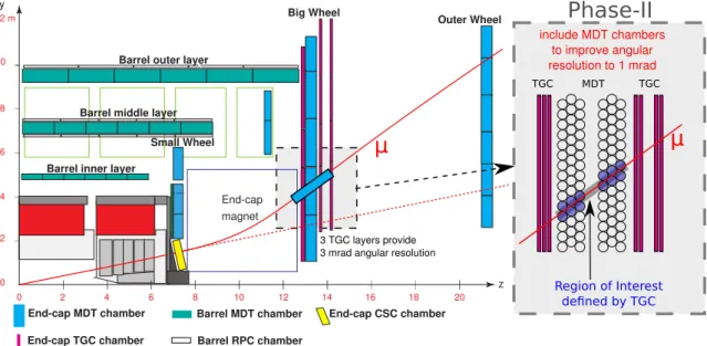
2. Including the MDT hit information in the Muon Trigger decision
In Fig. 3 the present Muon Trigger’s concept and its planned Phase-II upgrade is shown. After
emerging from the Interaction Point (IP), the muon is deflected in the magnetic field of the end-cap
magnet region between the Small Wheel (SM) and the Big Wheel (BW).
2 4 6 8 10 12 14 16 18 20 2
4 6 8 10 12 m
0
End-cap magnet
0 y
z Barrel MDT chamber End-cap CSC chamber
End-cap MDT chamber
Big Wheel Outer Wheel
End-cap TGC chamber Barrel RPC chamber Barrel outer layer
Barrel middle layer
Barrel inner layer
μ μ
TGC MDT TGC
Region of Interest defined by TGC include MDT chambers
to improve angular resolution to 1 mrad
3 TGC layers provide 3 mrad angular resolution
Phase-II
Small Wheel
Figure 3: Present scheme and Phase-II upgrade for the ATLAS Muon Trigger. Including the MDT chambers in the Muon Trigger improves the Big Wheel angular resolution.
The present Muon Trigger measures the angle of the muon with respect to a straight line, emerging from the interaction point with an accuracy of about 3 mrad.
As the present Muon Trigger is not capable of determining the direction of the muon before the magnetic field, muons not emerging from the IP can be misidentified as primary trigger candidates.
The main limitation of the present Muon Trigger is the missing feasibility to measure the deflection angle of the muons by the magnetic field.
During the Phase-I Upgrade of the MS the chambers of the Small Wheel will be replaced by chambers of a new technology with the capability of determining the angle in front of the end-cap magnet with a resolution of 1 mrad. This is called the New Small Wheel (NSW) [7].
Since a muon angle determination in front and behind the end-cap magnetic will be available, the p T of the muon can be determined with a higher accuracy and the Muon Trigger rate can be reduced by about a factor of 2 for a Muon Trigger threshold of 20 GeV.
To further decrease the Muon Trigger rate, we propose to include the BW MDT track infor- mation in the Muon Trigger. Due to the MDT chamber spatial resolution of less than 0.25 mm, compared to the TGC spatial resolution of a few centimetre, the BW angular resolution can be decreased to 1 mrad. According to the TGC strip size, the RoI is a 6 cm wide search area, corre- sponding to 2 to 3 drift tubes per MDT layer.
Using this TGC based track information, a more precise track can be fitted within the MDT
hits, which is used for muon- p T determination. According to this p T , the primary TGC based
trigger can be confirmed or rejected.
[GeV]
p
TOffline
10 15 20 25 30 35 40
Candidates /2 G eV
0 2000 4000 6000 8000 10000 12000 14000 16000 18000 20000 22000
ATLAS Preliminary Phase II upgrade study
= 8 TeV, 25 nsec s
using data
SW + Tile (expected Phase I) SW + Tile + Mask (proposed Phase I or II) SW + Tile + Mask + MDT (proposed Phase II)
Figure 4: Muon Trigger event distribution as a function of p T for 3 different trigger criteria at HL-LHC[8].
3. Potential of including MDT information in the ATLAS Muon Trigger decision
Based on an ATLAS data sample taken in 2012, center-of-mass energy of 8 TeV and a bunch- crossing interval of 25 nsec, the potential of including MDT in the ATLAS Muon Trigger has been investigated [8].
The events were selected by requiring the Muon Trigger with a 20 GeV transverse momentum threshold and the requirements expected for the Phase-I upgrade, particularly an already installed NSW, were assumed. The results of the study, namely event distributions based on different re- quirements, are shown in Fig. 4.
The requirements for the distributions are as following: The Phase-I upgrade leads to the white (unshaded) distribution, additionally removing all trigger candidates of inefficient detector regions leads to the red (parallel-hatched) distribution and further including the MDT track information in the Muon Trigger leads to the blue (cross-hatched) distribution.
It is obvious that including the hit information of the MDT in the Muon Trigger leads to a rate reduction for muon events below the nominal threshold. For a Muon Trigger threshold of 20 GeV the Muon Trigger rate can be reduced by about a factor of 2.
4. Technical implementation and track finding strategy
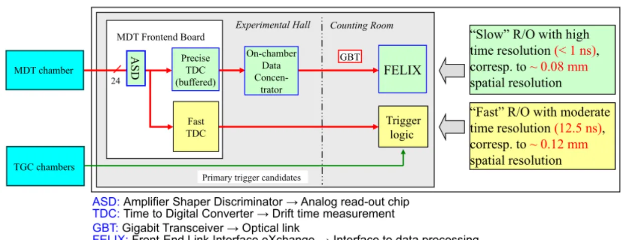
The existing MDT read-out chain is not capable of reading out the MDT hits fast enough to be used for the Muon Trigger. We therefore propose to implement the scheme shown in Fig. 5.
The MDT muon pulses are amplified, shaped and discriminated by the read-out chip (ASD)
and are, on the one hand, digitized by a precise Time-to-Digital-Converter (TDC) with 0.78 ns
resolution for later read-out and on the other hand, digitized by a second TDC with just 12.5 ns
resolution which sends the hit information to the Trigger Logic. When the TGCs detect a trigger
candidate, the information of the second TDC can be used for fast track reconstruction, leading to
a more precise p T determination.
FELIX
24
Trigger logic
On-chamberData Concen-
trator Precise GBT
TDC (buffered)
A S D
Fast TDC MDT Frontend Board
Counting Room Experimental Hall
Primary trigger candidates TGC chambers
“Slow” R/O with high time resolution (< 1 ns), corresp. to ~ 0.08 mm spatial resolution
“Fast” R/O with moderate time resolution (12.5 ns), corresp. to ~ 0.12 mm spatial resolution
ASD: Amplifier Shaper Discriminator → Analog read-out chip TDC: Time to Digital Converter → Drift time measurement GBT: Gigabit Transceiver → Optical link
FELIX: Front-End Link Interface eXchange → Interface to data processing
MDT chamberFigure 5: Technical implementation of MDT chamber read-out including a fast read-out path to make MDT hit information available for Muon Trigger.
The MDT read-out then consists of two parallel read-out chains. The first one corresponds to the existing MDT read-out and provides the high accuracy drift time information for offline track-reconstruction. The second chain supplies MDT hit coordinates with moderate accuracy fast enough for use inside the muon trigger latency [9].
To determine the p T of the Muon Trigger candidate within the given latency a fast track-finding algorithm has to be developed, capable of track-reconstruction under the HL-LHC conditions. At the HL-LHC we anticipate an occupancy of the MDT tubes with random hits of about 10% due to converted γ-rays and neutrons, which makes the recognition and reconstruction of muon tracks difficult. The main purpose of including the MDT hit information in Muon Trigger is to veto triggering on muons with a p T below the threshold of 20 GeV. However, care must be taken to not, by error, veto tracks above this threshold.
Therefore, a possible tracking algorithm needs a measure of quality (MoQ). We apply the following strategy: If the track reconstruction quality is poor, the primary trigger candidate is confirmed and the p T of the trigger candidates has to be determined at a higher trigger level. If no track fulfilling the requirements can be reconstructied, the primary trigger is also confirmed.
5. Simulation studies of a fast tracking algorithm
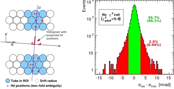
The concept for track-finding, based on the RoI from the TGC and the coordinates from the MDT, is shown in Fig. 6. It is the so-called histogram based pattern recognition with track recon- struction.
Each circle represents a drift tube. For track reconstruction all drift tubes within the RoI (blue circles) are considered. Due the approximately known angle of incidence of the muon, the drift radius of the tubes (red circle) can be reduced to two possible hit positions (red dots). We then project these hit positions along the direction of the expected track filling a histogram.
Subsequently, the histogram is scanned for peaks and the corresponding hits are used for linear
track fitting. Due to delta rays and background hits muon hits are masked which may lead to a
reduced hit quality.
α
zy Histogram with
projected hit positions
Tube in ROI Drift radius Hit positions (two−fold ambiguity)
μ
Figure 6: Histogram based pattern recognition. The algorithm projects the approximate hit positions in the direction perpendicular to the expected track fill- ing an one histogram.
[mrad]
- α
trueα
rec-15 -10 -5 0 5 10 15
1 10 10
210
310
4χ
2No cut
(90.1%) 95.7%
χ
2pdof<5.9
( )
(0.94%) 2.5%
E ve nts
Figure 7: Simulated event distribution for single muons with and without measure of quality. The simulation parameters are 10% uncorrelated back- ground occupancy (Big Wheel expectation for HL- LHC) and 200 ns dead time.
In order to obtain a MoQ of the fit, we use the tracks χ 2 per degree of freedom obtained from the linear fit.
The potential of the histogram based pattern recognition with track reconstruction has been investigated for the BW and the HL-LHC parameters for single muon tracks. Based on the approx- imate track information from the TGC with an angular resolution of 3 mrad, the track has been reconstructed using the algorithm which follows the procedure described above. As MoQ of this study the deviation of the reconstructed tracks angle α rec from the true angle α true has been defined.
With an increasing difference between α rec and α true , the error of p T determination of the muons is also increasing. If a low- p T muon is identified as high-p T muon, the correct momentum can be identified in a higher trigger level. If a high-p T muon is identified as low- p T resulting in a rejection of the trigger, this muon is lost for physics analysis. Therefore it is important to know the quality of the angle measurement.
Corresponding to the TGC angular resolution of 3 mrad, two categories for successfully recon- structed tracks have been defined. Events with a difference between α rec and α true below 3 mrad are part of the first category, the category “good”. All other events are part of the second category, the category “poor”.
The result of the simulation study is shown in Fig. 7. Without using the MoQ, 95.7% of the simulated events are within the category good and 2.5% of the simulated events are within the category poor. Using a MoQ, in particular the requirement of χ 2 per degree of freedom to be smaller than 5.9, 90.1% of all simulated events are within the category good and less than 1% are within the category poor.
It is possible to determine the trigger candidates p T for about 90% of all simulated events
with the necessary quality and therefore the confirmation or rejection of the primary TGC based
trigger is sufficiently reliable. For about 10% of all simulated events the algorithm is not capable of finding a track fulfilling the quality requirements and according to the strategy discussed before, these trigger candidates must be confirmed.
6. Hardware Demonstrator
To test the feasibility of the technical concept and to further study the fast track-fitting algo- rithm with real data, a hardware demonstrator setup (Test Setup Board, TSB) with reduced func- tionality, compared to the final technical implementation, has been designed.
HPTDC Entries 104564 Mean 225.9
RMS 191.6
Drifttime [ns]
0 100 200 300 400 500 600 700 800
Entries
0 50 100 150 200 250 300 350 400
HPTDC Entries 104564 Mean 225.9
RMS 191.6
Standard read-out Fast read-out
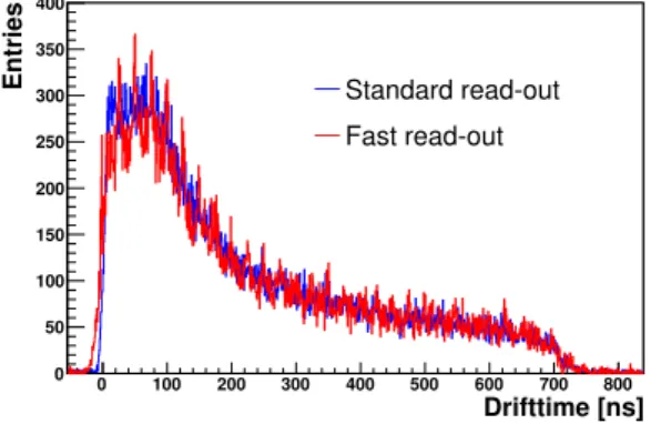
Figure 8: Comparison of an MDT drift time spectra acquired with standard and fast read-out.
The TSB is based on the already existing standard MDT read-out (SRO), but in addition a fast read-out (FRO) path is added. Both read-out paths are triggered by the passage of a cosmic muon, generating a scintillator signal and the data is recorded for offline analysis. The fast TDC’s frequency is 40 MHz while for the final imple- mentation 80 MHz are foreseen.
An MDT drift time spectrum measured with SRO and FRO is shown in Fig. 8. Due to the FRO’s lower time resolution, the accuracy for hits next to the tube’s wire is smaller and therefore a difference between the SRO’s and the FRO’s ris- ing edge is visible. As the FRO’s low precision TDC detect hits with 25 ns accuracy, the corre- sponding drift time spectrum shows spikes, which are smeared out due to trigger time correction, every 25 ns.
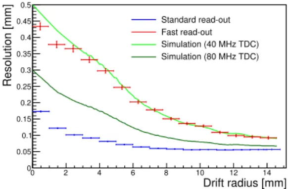
Fig. 9 shows the single tube resolution measured with SRO and FRO. Due to the lower time resolution of 25 ns, the spatial resolution measured with the FRO is worse than the one measured with the SRO (0.78 ns). The spatial resolution measured with the FRO is in agreement with the simulation which is based on the MDT tube’s drift velocity. For comparison Fig. 9 also shows the expected single tube resolution for a TDC with an 80 MHz clock (planned for ATLAS).
The FRO has been used to read out an MDT chamber (6 layers, 8 drift tubes each) at the CERN Gamma Irradiation Facility (GIF) [10].
During irradiation with a 500 Bq 137 Cs-source muon tracks have been measured. Due to configurable filters between γ-source and MDT chamber measurements with different background rates were possible.
The hit efficiency, which is background occupancy independent, of the SRO and FRO for two different background occupancies are shown in Fig. 10. As expected, the hit efficiency of SRO and FRO are matching.
7. Conclusion and Outlook
An extension of the current Muon Trigger using the precision Muon Drift Tube chambers
has been studied. The simulation shows a reduction of the ATLAS Muon Trigger rate below the
Drift radius [mm]
0 2 4 6 8 10 12 14
Resolution [mm]
0 0.05 0.1 0.15 0.2 0.25 0.3 0.35 0.4 0.45 0.5
Standard read-out Fast read-out Simulation (40 MHz TDC) Simulation (80 MHz TDC)
Figure 9: Resolution of standard and fast read-out and expected resolution for 80 MHz TDC.
Drift radius [mm]
0 2 4 6 8 10 12 14 16
Hi t-Ef fici enc y
0.8 0.82 0.84 0.86 0.88 0.9 0.92 0.94 0.96 0.98 1
Standard read-out (no background occupancy) Standard read-out (10% background occupancy) Fast read-out (no background occupancy) Fast read-out (10% background occupancy)
![Figure 1: Transverse momentum dependence of inclusive muon cross-sections [1].](https://thumb-eu.123doks.com/thumbv2/1library_info/4017403.1541511/2.892.153.758.284.513/figure-transverse-momentum-dependence-inclusive-muon-cross-sections.webp)
![Figure 4: Muon Trigger event distribution as a function of p T for 3 different trigger criteria at HL-LHC[8].](https://thumb-eu.123doks.com/thumbv2/1library_info/4017403.1541511/4.892.258.630.143.412/figure-muon-trigger-distribution-function-different-trigger-criteria.webp)