Drift Tube Chambers for the ATLAS Barrel Muon Spectrometer
Jörg Dubbert ∗
Max-Planck-Insitut für Physik Munich, Germany
E-mail: joerg.dubbert@mppmu.mpg.de
Manfred Groh
Max-Planck-Insitut für Physik
E-mail: manfred.groh@mppmu.mpg.de
Sandra Horvat
Max-Planck-Insitut für Physik
E-mail: sandra.horvat@mppmu.mpg.de
Oliver Kortner
Max-Planck-Insitut für Physik
E-mail: Oliver.Kortner@mppmu.mpg.de
Hubert Kroha
Max-Planck-Insitut für Physik
E-mail: hubert.kroha@mppmu.mpg.de
Susanne Mohrdieck-Moeck Max-Planck-Insitut für Physik
E-mail: susanne.mohrdieck@mppmu.mpg.de
Robert Richter
Max-Planck-Insitut für Physik
E-mail: robert.richter@mppmu.mpg.de
Otmar Biebel
Department für Physik, Ludwig-Maximilians-Universität München E-mail: otmar.biebel@physik.uni-muenchen.de
Johannes Elmsheuser
Department für Physik, Ludwig-Maximilians-Universität München E-mail: johannes.elmsheuser@physik.uni-muenchen.de
Marion Erlebach
Department für Physik, Ludwig-Maximilians-Universität München E-mail: marion.erlebach@physik.uni-muenchen.de Frank Fiedler
PoS(HEP2005)390 PoS(HEP2005)390
Test, Integration and Commissioning of Monitored Drift Tube Chambers for the ATLAS Barrel Muon Spectrometer Jörg Dubbert
Department für Physik, Ludwig-Maximilians-Universität München E-mail: frank.fiedler@physik.uni-muenchen.de
Doris Merkl
Department für Physik, Ludwig-Maximilians-Universität München E-mail: doris.merkl@physik.uni-muenchen.de
Ralf Hertenberger
Department für Physik, Ludwig-Maximilians-Universität München E-mail: ralf.hertenberger@physik.uni-muenchen.de
Thomas Nunnemann
Department für Physik, Ludwig-Maximilians-Universität München E-mail: thomas.nunnemann@physik.uni-muenchen.de
Raphael Mameghani
Department für Physik, Ludwig-Maximilians-Universität München E-mail: raphael.mameghani@physik.uni-muenchen.de
Felix Rauscher
Department für Physik, Ludwig-Maximilians-Universität München E-mail: felix.rauscher@physik.uni-muenchen.de
Dorothee Schaile
Department für Physik, Ludwig-Maximilians-Universität München E-mail: dorothee.schaile@physik.uni-muenchen.de
Arnold Staude
Department für Physik, Ludwig-Maximilians-Universität München E-mail: arnold.staude@physik.uni-muenchen.de
Raimund Ströhmer
Department für Physik, Ludwig-Maximilians-Universität München E-mail: raimund.stroehmer@physik.uni-muenchen.de
Cornelius F. Vollmer
Department für Physik, Ludwig-Maximilians-Universität München E-mail: fritz.vollmer@physik.uni-muenchen.de
PoS(HEP2005)390
390 / 2 390/2
PoS(HEP2005)390
toroidal air-core magnet is instrumented with three layers of Monitored Drift Tube (MDT) cham- bers as precision tracking detectors; the middle and outer layers of drift chambers also carry Resistive Plate chambers (RPCs) of the trigger system. The barrel part of the spectrometer con- sists of a total of 682 muon stations, with sizes ranging from 1 m 2 to 11 m 2 . The installation of the muon detectors has started in January 2005. At the Max-Planck-Institut für Physik and the Ludwig-Maximilians-University in Munich, 88 MDTs of the second largest chamber type—each covering an area of up to 8 m 2 —are being built for the outermost barrel region. The MDT cham- bers have to pass a series of stringent tests before installation to ensure their proper operation in the experiment. At the production site in Munich, these tests include gas tightness, high voltage stability and measurements of the noise rate, and the response to cosmic muons. In addition, the individual wire positions and electronic time offsets of the drift tubes are determined from the cosmic ray data. After shipment to CERN, a subset of the tests is repeated and the MDT cham- bers are integrated on a common support frame with the trigger chambers. The completed muon station is is further checked with cosmic rays. All results are stored in the ATLAS commissioning database and constitute an important basis for LHC data taking. We present the test methods and results, an overview on the integration work of the muon detectors and report on the experience with the installation of the first stations in the ATLAS experiment.
International Europhysics Conference on High Energy Physics July 21st - 27th 2005
Lisboa, Portugal
∗
Speaker.
PoS(HEP2005)390 PoS(HEP2005)390
Test, Integration and Commissioning of Monitored Drift Tube Chambers for the ATLAS Barrel Muon Spectrometer Jörg Dubbert
1. Introduction
The ATLAS (A Toroidal LHC ApparatuS) experiment is one of the two multi-purpose detec- tors at the Large Hadron Collider (LHC) at CERN. Its muon spectrometer [1] has been designed to be capable of stand-alone operation (i.e. it does not require information from the inner detector or calorimeters to reconstruct muon tracks) with a resolution of better than 10% for muon momenta up to 1 TeV.
In the barrel region of the muon spectrometer a three point sagitta measurement with Mon- itored Drift Tube (MDT) chambers is used to determine the muon momentum. To achieve the desired precision, each MDT must reach a resolution of better than 50 µ m.
ATLAS MDT chambers [1] consist of two multilayers, each built of 3 or 4 layers of densely packed drift tubes mounted on a support frame; the chamber sizes vary from about 1 m 2 to 11 m 2 while tube lengths range from 1 to 6 m. The individual drift tubes have an outer diameter of 30 mm and a wall thickness of 400 µ m. A single anode wire with a diameter of 50 µ m is stretched in the center of the tube and fixed only at the tube ends; the sag of the wires in the tubes can be compensated by bending the chamber with respect to the support frame.
The determination of the impact radius of a charged particle within a drift tube is based on the measurement of the drift time of the primary ionization electrons to the anode wire; a so- called rt-relation is then used to convert drift time information to a radius prediction. In the case of MDT chambers this rt-relation can be determined by an iterative self-calibrating algorithm, the auto-calibration [2]. An average single tube resolution of 80 µ m has been achieved with an Ar/CO 2 =93/7 gas mixture at 3 bar absolute pressure at a gas gain of 2 × 10 4 . The maximum drift time for electrons from hits near the tube wall to the anode wire is about 700 ns.
The geometry of the drift tube chambers, as well as the positions of all MDTs in the detector, are constantly monitored by optical alignment systems [1, 3].
2. Tests and Commissioning of MDT Chambers
The Max-Planck-Institut für Physik (MPI) and the Ludwig-Maximilians-University (LMU) at Munich built 88 MDT chambers for the outermost barrel layer of the muon spectrometer, most of them consisting of 432 drift tubes arranged in 2 × 3 layers and measuring 4 m × 2.2 m × 0.5 m.
To ensure the necessary geometrical precision and the proper operation of the MDT cham- bers, the assembly process is monitored at each step [4, 5]. The most important parameters of the individual drift tubes—gas leak rate, anode wire tension, dark current and the wire position, the latter with a precision of a few µ m with an X-Ray tomograph—are measured immediately after their production. During chamber construction geometrical parameters—such as e.g. the position of reference surfaces at both tube ends and the position of the chamber support frame during glue- ing of the tube layers—are measured. Combined with the knowledge of the single tube anode wire positions, these measurements yield the chamber geometry, i.e. the position of all anode wires and the layer parameters of the MDT.
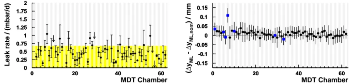
After the chamber has been assembled, each connection of a drift tube to the common gas distribution bar is checked to conform with the leak rate limit of 1 · 10 -8 mbar l/s and the leak rate of each multilayer is determined from the temperature corrected pressure drop over a time span of
PoS(HEP2005)390
390 / 2 390/4
PoS(HEP2005)390
0 0.25 0.5 0.75 1 1.25 1.5 1.75 2
0 20 40 60
0 0.25 0.5 0.75 1 1.25 1.5 1.75 2
0 20 40 60
MDT Chamber
Leak rate / (mbar/d)
-0.15-0.1 -0.05 0 0.05 0.1 0.15
0 20 40 60
-0.15 -0.1 -0.05 0 0.05 0.1 0.15
0 20 40 60