Pyrolysis/Gasification
Evaluation of Recent Developments
Regarding Alternative Thermal Waste Treatment with a Focus on Depolymerisation Processes
Peter Quicker
1. Chemical recycling routes for plastics ...362
1.1. Combustion and CO2 utilization ...362
1.2. Gasification and syngas utilization ...363
1.2.1. SVZ fixed bed gasifier ...363
1.2.2. Showa Denko – Ebara ...365
1.3. Pyrolysis and oil upgrading ...367
1.4. Liquefaction and oil upgrading ...368
1.4.1. Dieselwest – Recenso ...368
2. Conclusion ...369 Many plastic waste fractions are not recyclable as a material anymore by simply melting and re-granulating them. Impurities and contaminations would be transferred to the product. Nevertheless, recycling quotas prescribed by the European Union are increas- ing. This makes it inevitable – independent of its ecological sense and rationality – to find alternative possibilities to recover new plastics from waste plastic fractions.
Depolymerisation processes offer this option and are now highly discussed as chemical recycling. Despite the negative experiences with alternative thermal waste treatment processes in the past, they are again praised as the solution, this time for plastic recycling.
chemical recycling of plastics
CO2 - capture CO2 - capture
Upgrading Upgrading
H2-electrolysis Synthesis of hydrocarbons Chemical synthesis (Dream reactions)
Synthesis of hydrocarbons Synthesis of hydrocarbons Combustion CO2+ H2O
Gasification CO + H2 Pyrolysis Gas, oils, waxes
Liquefaction oils, waxes
Depolymerisation (in an oil bath) Solvolysis
Pressure hydrogenation
Refining and fractionation Solution and precipitation
H2-treatment at high pressure and temperature
Figure 1: Basic options for chemical recycling of plastics currently under discussion
Pyrolysis/Gasification
1. Chemical recycling routes for plastics
Depolymerisation of plastics may happen in different ways. In principle, all thermo- chemical processes can be applied: combustion, gasification and pyrolysis. Beyond that, liquefaction processes are available that work with additives or solvents.
Figure 1 gives an overview of possible options for thermochemical decomposing of polymers. All of them may serve as a first step of plastic recovery, even combustion.
In the following subchapters, these routes are shortly discussed, and most advanced process approaches are presented in detail.
1.1. Combustion and CO
2utilization
The simplest way to depolymerise plastics is to incinerate them. The hydrocarbons (as any fuel that consists mainly of hydrocarbons) are transformed into to CO2 and H2O.
If the CO2 is captured, it can be utilized again for the production of new polymers.
An interesting concept in this context is the oxy-fuel process. The absence of nitrogen (due to use of pure oxygen as oxidation agent) in the off gas has several advantages:
minor gas flows and in consequence facilities that are more compact and have less heat losses and possibly lower nitrogen emissions due to the necessary flue gas recirculation.
The nitrogen-free off-gas (normally more than 50 vol.-% of the gas) offers a smart option for CO2 recovery, just by condensation of the containing water and precipitation of possibly present contaminants, like dust, HCl or organic compounds. Energy intensive pressure or temperature swing processes are not necessary.
The purified CO2 can be used as building blocks for new polymers or other organic compounds. Two generally different pathways are currently discussed for this purpose.
One frequently mentioned approach is water electrolysis with subsequent production of methane or other (liquid) fuels or chemicals (Power-to-Gas, PtG, P2G; Power-to-X, PtX) with the generated hydrogen and the carbon dioxide from the flue gas.
Since CO2 and H2O are the products of total oxidation of hydrocarbons, all the energy gained during combustion has to be returned into the molecular structure, to remove the oxygen and rebuild hydrocarbon structures. This makes the availability of cheap (and ideally climate neutral) electricity a pre-requisite for this route.
Another thermodynamically much more interesting approach is the substitution of chemicals in the feed of preferably exothermic processes that anyway release enough energy to break the bondings in the CO2 molecules for integration of the carbon atom into the polymer product. These so called dream reactions offer a chance for utilization of clean CO2, but the amounts that can be utilized on this routes are of course very limited. First industrial manufacturing processes are operated by Covestro in Germany.
Since it is not expected that the combustion and following re-polymerization of the resulting CO2 will be a political accepted process to fulfil the recycling quotas, this approach is not discussed here further.
Pyrolysis/Gasification
1.2. Gasification and syngas utilization
One of the basic processes in chemical industry is the utilization of synthesis gas (syngas:
H2 + CO mixture). This gas is the origin of a variety of chemical products. Therefore, the idea is evident, to transfer (plastic) waste by gasification into syngas and thereby create a highly demanded product.
Despite this evident idea and many approaches in the past, it is still (and will presumably also stay in future) a real technical challenge to produce a high quality syngas from waste. This is not possible with municipal solid waste as a feedstock, at least not with an acceptable effort. If the waste is sophistically pre-treated or if already source-separated plastics are used as a feedstock, a gas for synthesis can be generated, after upgrading with high effort and costs. An economic operation of such installations cannot be expected.
Nevertheless, there are two facilities that have to be mentioned in this context, which produce(d) high grade chemicals from waste on an industrial level:
• SVZ Schwarze Pumpe, Cottbus (methanol)
• Showa Denko, Kawasaki (ammonia)
1.2.1. SVZ fixed bed gasifier Fixed bed pressure gasifiers – shaft gasifiers equipped with a rotary grate – were used at the industrial site Schwarze Pumpe to gasify lignite for the supply of city gas in the former GDR.
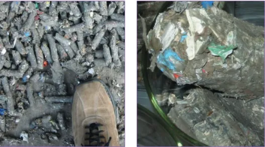
After dismissing city gas production, the fixed bed pressure reactors were retrofitted to treat different waste mixtures with coal addition. Waste types treated in Schwarze Pumpe included pelletized refuse derived fuels from processed household and similar commercial waste, compacted mixtures of plastic waste, woodchips, sewage sludge briquettes, tar sludge pellets and shredder light fraction (Figure 2).
Figure 2: Input materials of the fixed bed pressure gasifier in SVZ Schwarze Pumpe
Pyrolysis/Gasification
Three reactor types had operating permits in Schwarze Pumpe:
• Fixed bed pressure gasifier
• Entrained-flow gasifier for liquids
• British-Gas-Lurgi (BGL-) gasifier with molten slag discharge
Fixed bed and BGL gasifier were intended to treat solid input materials whereas the entrained-flow gasifier was to be operated with liquid waste.
Household waste and commercial waste similar to household waste were subject to complex pre-treatment and conditioning in several stages to produce a refuse derived fuel with high calorific value.
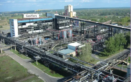
The fixed bed pressure gasifier had an available capacity of 12.5 Mg/h each with an annual maximum capacity of 444,000 Mg of solid waste and lignite/hard coal in various mixing ratios (Figure 3).
A mixture of lignite briquettes and/or hard coal was gasified in the fixed bed reactors (3.6 m diameter) together with the pre-treated waste materials. Steam and oxygen were used as gasification agents, they were mixed using the injector principle and injected through the rotary grate with a pressure of 27 bar. Reactors were operated at about 75 % of the available filling height. This was achieved by systematic interruptions of the fuel feed to achieve a better flow through the gasification bed. A slurry product containing up to 30 % solids and consisting of water and hydrocarbons was added to the solid gasification. Normally, the slurry input amounted to a maximum share of under 20 % of the feedstock. Gasification temperatures in the oxidizing zone of the reactor were between 1,200 and 1,300 °C and dropped to around 450 °C at the raw gas discharge because of heat loss and reduction processes.
Ash was removed by a rotary grate, an ash lock, a drop shaft and a scraping conveyor.
In a scrubber, the gas was washed and cooled down with water. Raw synthesis gases were cleaned using the Rectisol process. In the conversion facility, a partial flow of the raw gas was treated: carbon monoxide was converted to CO2 and H2 using steam in order to achieve the optimum ratio of CO2/CO/H2 for synthesis of methanol.
In the methanol plant, the conditioned syngas ran through a fine cleaning process, to remove the remaining impurities and catalyst poisons and was then compressed.
Raw methanol generated in methanol synthesis was distilled to produce high purity methanol.
After the political turn in 1989, the plant was first owned by the Berliner Wasserbe- triebe. In the middle of 1997, commercial operation started in the recycling chain of conditioning – gasification – methanol synthesis – power generation. After temporary ownership by several companies with little success, Sustec took over in October 2005.
Due to many problems, the necessary permanent availability of the plant could not be achieved. The whole site could not be operated economically. Despite massive govern- ment aid, Sustec had to shut down the waste gasification in the middle of 2007. Sales could not prevent bankruptcy. The gasifiers have been dismantled.
Pyrolysis/Gasification
1.2.2. Showa Denko – Ebara Ebara Corporation and Ube Industries Ltd. began in the 1990s the cooperative devel- opment of a two-stage gasification process. The objective was to turn mixed feedstock, e.g. plastic wastes, shredder dust and sewage sludge together with coal into a syngas for material utilization.
In 2003, a full-scale technical plant with a production capacity of 195 Mg/d went into operation at the site of the chemical company Showa Denko K.K in Kawasaki (Japan), to deliver hydrogen for ammonia production.
For ammonia synthesis, H2 has to be produced with the maximum possible purity from plastic waste. Therefore, an extensive feedstock preparation is necessary. This begins at an external processing plant, where plastic waste from households and industry is gathered and prepared by sorting, pre-crushing and compaction to bales. These bales are then transported to the preparation facility at the Showa Denko plant.
At the facility, the plastic bales are opened and shredded. The purpose is to reduce the particle size for the subsequent agglomeration and to remove possible metal impurities (1 to 2 % of the input). Iron pieces are separated after shredding via magnetic separation.
There is no removal of non-ferrous metals.
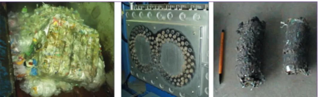
The shredded plastic is fed into two parallel extruders for compaction. Hereby the plas- tics are heated, partly molten and finally stick together. The heat also lowers the moisture content of the material. The produced briquettes have a length of approximately 15 cm.
Figure 3: Fixed bed pressure gasification unit with surroundings at SVZ Schwarze Pumpe Gasifiers
Pyrolysis/Gasification
Figure 4 shows the shredding of a plastic bale, one of the extruders and the compacted material ready for feeding into the gasifier.
Figure 4: Feedstock Showa Denko plastic gasification; left: plastic bales at delivery; centre: extruder;
right: compacted plastics
The extruders work 22 hours a day. Each of them needs a daily maintenance period of approximately 2 hours. In this time the extruders are cleaned manually (clogged die holes). The extruders have to be cooled from the outside via atomized water mist to prevent overheating.
The plastic briquettes are sieved in a vibrating screen to separate fine materials and non-uniform briquettes and then transported via trucks to the gasifier.
Core of the process are two pressurized gasification stages, operated at different temperatures. The pretreated feedstock is converted in these two steps into a H2- and CO-rich syngas.
The first reactor is a rotating fluidized-bed gasifier, operated at 600 to 800 °C. The pretreated plastic briquettes are fed at the top of the gasifier at a constant rate of 195 Mg/d. The main purpose of the technology is to intensify horizontal intermixture of the bed in order to increase turbulence and accelerate the conversion.
A mixture of steam and oxygen is used as fluidizing gas and gasification agent. The plastic waste is pyrolysed and gasified inside the fluidizing bed into a mixture of hy- drogen, carbon monoxide, hydrocarbons, char and particles that leaves the rotating fluidized bed to the second gasifier. Ashes, metals and other inorganics are discharged.
The generated gas from the first reactor enters the second gasifier at the top. The high injection speed and the geometry of the reactor cause a swirl flow, which is directed downwards. Preheated oxygen and steam are added from the top and the sidewalls. The partial oxidation of the gas increases the temperature up to 1,300 to 1,500 °C. Conse- quently, the ash is melting within the gas stream and the resulting slag is transported with the swirl to the reactor bottom. To prevent clogging of the reactor walls, the di- ameter of the swirl should be smaller than the reactor. This is however hard to control and results in ongoing problems with slagging and damage of the refractory material.
At the bottom of the furnace, the gases and slag mists are forced to pass through a water bath. The gas is already quenched via water nozzles before entering the water bath.
Pyrolysis/Gasification
The gas leaves the water with approximately 200 °C and leaves. The slag stays as gran- ules inside the water bath, where it accumulates at the bottom of the tank and can be purged via a lock hopper.
Gasifier
NH3 synthesis
Figure 5: Plastic waste gasifier and ammonia synthesis at Showa Denko, Kawasaki
For cleaning, the syngas is fed to an alkaline scrubber. HCl and other halides from plastics like PVC are separated from the gas by adding sodium hydroxide. Increasing the hydrogen content is achieved via water-gas shift reaction in a following reactor at 350 °C. Subsequently H2S and COS are separated from the syngas. The CO2 has to be removed from the gas for ammonia production, to prevent formation of carbamates.
Therefore, the gas is cooled down and pressurized to liquefy and separate the CO2, which is marketed as dry ice. The remaining hydrogen is used as feedstock for ammo- nia synthesis (Haber-Bosch process). Approximately one third of hydrogen has to be added from fossil production sources (natural gas).
1.3. Pyrolysis and oil upgrading
Pyrolysis is a very well known process, with centuries of experience in technical ap- plications, e.g. in charcoal making or hard coal coking. As in these two examples, the desired product normally is the solid residue of the process – the charcoal or coke (even though the side products may also be used).
Applying pyrolysis to produce valuables from decomposed waste plastics implies two simultaneous challenges: the utilization of a very heterogeneous feedstock and the upgrading of the low quality gaseous and/or liquid products, recovered thereof. In combination, this was until today obviously a too high obstacle to bring a pyrolysis process that is part of a chemical recovery chain to technical maturity or even to long- term operation, as depicted for the two gasification examples above (cf. Chapter 1.2).
Pyrolysis/Gasification
Nevertheless, there are some approaches that focus on the (decentralized) depolym- erisation of pre-sorted and treated plastic fractions to generate oils and waxes by condensation of the pyrolysis vapours, which may be possible input materials for the big centralized steam crackers of the chemical industry. This is a potentially interesting approach, because the most challenging step of the recovery process, the upgrading of the pyrolysis product, is transferred to the chemical industry with far reaching experi- ence and sufficiently plant sizes to dilute the recovered oils to an extent that no negative influence on the operation or product of the steam cracker is expected.
Since there is currently no known pyrolysis plant in (semi)industrial operation that produces relevant amounts for further upgrading, e.g. in the chemical industry, no process example can be presented here.
1.4. Liquefaction and oil upgrading
As shown in Figure 1, there is more than one option to (directly) liquefy plastic waste.
A very elegant approach is solvolysis, the specific solution of the polymer with a tailored solvent. The CreaSolv process is such an approach, currently under development for technical polystyrene recovery.
Hydrogenation at high pressure aims to generate saturated products with a low number of heteroatoms. Pressure ranges from 100 to several hundred bar, temperatures are between 300 and 350 °C. The use of H2 as hydrogenation agent leads to a comparatively high product quality at the price of high operating efforts. This may be one reason, why so far, no industrial examples are known that are applying this approach for plastics recycling.
By contrast, there are many activities in the field of depolymerisation of plastics in oil baths. As an example, the process of Dieselwest in Ennigerloh, Germany is presented.
With an estimated output of approximately 400 litres per hour, the company operates a pilot plant on a semi-industrial level and currently cooperates with the chemical industry to evaluate the performance of their product during upgrading, e.g. in steam crackers.
1.4.1. Dieselwest – Recenso
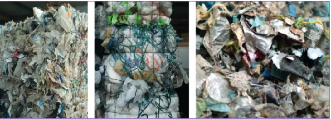
The Dieselwest process (Figure 7) is a catalytic depolymerisation process. Prior to the reactor, a catalyst based on aluminium-silicate and iron oxide for sulphur fixation are added to the feedstock. Input material (Figure 6) with a grain size of less than 30 mm and free of ferrous and non-ferrous metals is conveyed with a screw. To prevent oxygen intake, the reactor is separated from the surrounding atmosphere by a lock system purged with nitrogen. The reactor operates according to the principle heavy oil sump phase at a temperature of circa 320 °C. Before start-up a start-up oil has to be filled into the reactor. This oil is supposed to be consumed only at the same ratio that new oil is generated from the input material.
Pyrolysis/Gasifi cation
Th e process is powered by electrically driven turbines, which keep the sump phase in rotation for a uniform temperature distribution. In order to prevent damage to the turbines, complete reliable removal of metals from the input material is inevitable. Th e reaction product is evaporated at operating temperatures. In a column, it is condensed and then dewatered. Small amounts of non-condensable gases are burned in a regener- ative thermal oxidizer. A mixture of solid material and catalyst is regularly discharged using a pumping system located at the reactor sump. In a settling tank, separated from the reactor by a lock, the mixture of catalyst and other solid residues is separated from the oily phase, which is then recirculated.
Figure 6: Feedstocks for Dieselwest pilot plant for plastic liquefaction at Ennigerloh
Th e product oil mainly consists of the distillable fraction of the gasoil. Specifi cations of EN 590 for diesel fuels are not fulfi lled. For example, sulphur and water contents signifi cantly exceed the limits, depending on the input material.
2. Conclusion
Since recycling quotas for plastic in the future can only be met by chemical recycling approaches, many alternative thermal treatment options for waste processing are ex- periencing a renaissance – even in countries like Germany, where these approaches have a very bad reputation due to several failed projects in 1990s.
Figure 7:
Dieselwest pilot plant for plastic liquefaction at Ennigerloh
Pyrolysis/Gasification
Currently, it has to be determined which of the approaches can play a relevant role as an element in future chemical recycling processes.
Robust and decentralized approaches applicable in small units, like liquefaction and possibly pyrolysis, have the potential to produce a raw oil that may serve as a feedstock for further upgrading processes in the chemical industry. Such approaches keep the investments and therefore the risks low and allow the application of existing infra- structure and technology.
On the other hand, it may be questionable if the risk of investments in large-scale applications for plastic gasification and syngas production is worth the outcome. Long- term experience in SVZ Schwarze Pumpe and at Showa Denko have demonstrated the technical feasibility of homogeneous, plastic-rich waste fractions. However, they have also shown the technical problems and high effort necessary for plant operation, even after years of experience.
Finally, it should not be forgotten that, according to many experts, the approach of chemical recycling is not the right way. The special value of plastic, the polymerized structure, is decomposed and transformed into an inferior product, such as a low quality oil that has to be treated with great effort in order to turn it back into plastic.
A large share of our energy demand today is met by the combustion of oil and gas, which would be excellent feedstocks for the chemical industry that do not require sophisticated pretreatment. The obvious question arises why we do not use these fuels for the production of plastics and instead generate their share of usable energy from waste plastics that can no longer be material recycled.
Remark
Parts of this article are taken from report Status of Alternative Techniques for Thermal Waste Treatment, Expert Report for the Federal Ministry for the Environment, Nature Conservation, Building and Safety, Project No. Z 6 –30 345/18, Report No. 29217.
Contact Person
Professor Dr.-Ing. Peter Quicker RWTH Aachen University Unit of Technology of Fuels Wüllnerstraße 2
52062 Aachen GERMANY +49 2418095705
quicker@teer.rwth-aachen.de
Bibliografische Information der Deutschen Nationalbibliothek Die Deutsche Nationalbibliothek verzeichnet diese Publikation in der Deutschen Nationalbibliografie; detaillierte bibliografische Daten sind im Internet über http://dnb.dnb.de abrufbar
Thiel, S.; Thomé-Kozmiensky, E.; Winter, F.; Juchelková, D. (Eds.):
Waste Management, Volume 9 – Waste-to-Energy –
ISBN 978-3-944310-48-0 Thomé-Kozmiensky Verlag GmbH
Copyright: Elisabeth Thomé-Kozmiensky, M.Sc., Dr.-Ing. Stephanie Thiel All rights reserved
Publisher: Thomé-Kozmiensky Verlag GmbH • Neuruppin 2019 Editorial office: Dr.-Ing. Stephanie Thiel, Elisabeth Thomé-Kozmiensky, M.Sc.
Layout: Claudia Naumann-Deppe, Janin Burbott-Seidel, Sarah Pietsch, Ginette Teske, Roland Richter, Cordula Müller, Gabi Spiegel Printing: Universal Medien GmbH, Munich
This work is protected by copyright. The rights founded by this, particularly those of translation, reprinting, lecturing, extraction of illustrations and tables, broadcasting, micro- filming or reproduction by other means and storing in a retrieval system, remain reserved, even for exploitation only of excerpts. Reproduction of this work or of part of this work, also in individual cases, is only permissible within the limits of the legal provisions of the copyright law of the Federal Republic of Germany from 9 September 1965 in the currently valid revision. There is a fundamental duty to pay for this. Infringements are subject to the penal provisions of the copyright law.
The repeating of commonly used names, trade names, goods descriptions etc. in this work does not permit, even without specific mention, the assumption that such names are to be considered free under the terms of the law concerning goods descriptions and trade mark protection and can thus be used by anyone.
Should reference be made in this work, directly or indirectly, to laws, regulations or guide- lines, e.g. DIN, VDI, VDE, VGB, or these are quoted from, then the publisher cannot ac- cept any guarantee for correctness, completeness or currency. It is recommended to refer to the complete regulations or guidelines in their currently valid versions if required for ones own work.