Dorfstraße 51
D-16816 Nietwerder-Neuruppin
Phone: +49.3391-45.45-0 • Fax +49.3391-45.45-10 E-Mail: order@vivis.de
Waste Management
Rüdiger Margraf
Waste Incineration
Figure 7:
Rough scheme dry hydration CaO Dosing balance
H2O
Dry hydrator CaO
CaO Silo
Ca(OH)2 Ca(OH)2
Silo towards lime dosing TIC
Several plants in Germany have been provided with this technology.
Figure 8 shows a plant, realised with a dry hydrator for a Ca(OH)2 production capacity of approximately 3 t/h.
Figure 8: RDF incineration plant EEW Premnitz / Germany As alternative there is the possibility to install the dry hydrator close to the additive
2 can now be injected directly into the reactor without temporary storage in a silo.
Figure 9 shows such a dry hydrator as well as the corresponding WtE plant.
Verbrennungs-rost Gewebefilter Elektro- filter Sprüh-
trockner Kamin
Dampf- kessel MüllkranAufgabe-trichter
Müll- bunkerVerbrennungs-luftgebläsevorrichtungAufgabe-Platten-wände TrogkettenfördererEntschlackung/
Ammoniak-Wasser-Eindüsung Kessel- entaschung
AbgaswäscherDruckerhöhungs-gebläse Adsorbenssilo
Feuerraum Primär-luft
Figure 3:
Karl J. Thomé-Kozmiensky
Volume 2
WASTE MANAGEMENT
Luciano Pelloni
Waste Management Recycling Composting Fermentation Mechanical-Biological Treatment Energy Recovery from Waste Sewage Sludge Treatment
Thomé-Kozmiensky und PelloniWASTE MANAGEMENT
2
2
Thomé-Kozmiensky und Pelloni
Karl J. Thomé-Kozmiensky
Volume 3 Recycling and Recovery
WASTE MANAGEMENT
Stephanie Thiel
WASTE MANAGEMENTThomé-Kozmiensky und Thiel
3
, Thiel
5
2
Thomé-Kozmiensky und Pelloni
Volume 6 Waste-to-Energy
WASTE MANAGEMENT
Stephanie Thiel Karl J. Thomé-Kozmiensky
6
WASTE MANAGEMENTK. J. Thomé-Kozmiensky & S. Thiel
WASTE MANAGEMENT Volume 2
KARL J. THOMÉ-KOZMIENSKY STEPHANIE THIEL HRSG.
Copyright © 2011 TK Verlag Karl Thomé-KozmienskyAlle Rechte vorbehalten.
Das Einspeisen der Daten in Netzwerke ist untersagt.
WASTE MANAGEMENT Volume 3
KARL J. THOMÉ-KOZMIENSKY STEPHANIE THIEL HRSG.
Copyright © 2011 TK Verlag Karl Thomé-Kozmiensky Alle Rechte vorbehalten.
Das Einspeisen der Daten in Netzwerke ist untersagt.
Waste Management, Volume 2 – 7 • CD Waste Management, Volume 2 and 3
310.00 EUR
save 140.00 EUR
Package Price
Editors: Thomé-Kozmiensky (et.al.)
Waste Management, Volume 5 (2015) ISBN: 978-3-944310-22-0 90.00 EUR Waste Management, Volume 2 (2011) ISBN: 978-3-935317-69-6 CD includes translations in 50.00 EUR + CD Waste Management, Volume 2 ISBN: 978-3-935317-70-2 Polish and German
Waste Management, Volume 3 (2012) ISBN: 978-3-935317-83-2 CD includes translations in 50.00 EUR + CD Waste Management, Volume 3 ISBN: 978-3-935317-84-9 various languages
Waste Management, Volume 4 (2014) ISBN: 978-3-944310-15-2 50.00 EUR
Waste Management, Volume 6 (2016) ISBN: 978-3-944310-29-9 90.00 EUR Waste Management, Volume 7 (2017) ISBN: 978-3-944310-37-4 120.00 EUR
IRRC IRRC
2
Thomé-Kozmiensky und Pelloni
Volume 7 Waste-to-Energy
WASTE MANAGEMENT 7
WASTE MANAGEMENTK. J. Thomé-Kozmiensky et al.
Karl J. Thomé-Kozmiensky † Stephanie Thiel Elisabeth Thomé-Kozmiensky Franz Winter Dagmar Juchelková
TK Verlag GmbH
order now www. .de
hardc
over with coloured illustrations
MBT and SRF
Mechanical-Biological Waste Treatment Plants in Croatia
Renato Sarc, Klara Perovic, Irena Relic and Karl Lorber
1. Introduction ...316
1.1. Waste origin and amounts ...316
1.2. Recycling rate of MSW ...317
1.3. Mixed municipal solid waste ...317
1.4. Treatment of mixed municipal solid waste ...318
1.5. Waste-to-Energy in Croatia ...320
1.6. Co-Incineration in cement industry in Croatia ...321
1.7. Further goals and priorities according to the Waste Management Plan 2017 to 2022 ...322
2. Materials and methods ...323
3. Results and discussion ...324
3.1. Input waste materials for production of SRF ...324
3.2. Output waste materials from MBT plants ...324
3.3. Applied technology ...325
3.3.1. MBT Varaždin ...325
3.3.2. WMC Kaštijun and WMC MarišĆina ...326
3.4. Results from own investigations ...329
3.4.1. Results from sieving analyses ...330
3.4.2. Results from physical-chemical analyses ...331
4. Conclusions ...333
5. References ...334 In the present contribution, the current situation as well as future strategy with goals for sustainable development of municipal waste management in Croatia are shown.
Additionally, waste amounts, recycling rates, mechanical-biological treatment plants (planned and in operation), cement industry and other relevant waste management issues are discussed. Finally, in total three solid recovered fuel (SRF) Premium Quality samples from all three mechanical-biological treatment plants that are currently in operation have been extensively investigated and selected results are presented.
´ ´
MBT and SRF
1. Introduction
1.1. Waste origin and amounts
In the Republic of Croatia (RC), the current status in waste management is presented in the Waste Management Plan (WMP) for the period 2017-2022 [22], a national do- cument that introduces the current state and an action plan with aims and measures for further development up to 2022, already considering selected targets of the new circular economy package [20]. According to the document, in 2014 a total of around 3.7 million tonnes of produced waste (municipal and production waste) were reported.
Of the total amount of waste, non-hazardous waste constitutes 97 %, while hazardous waste constitutes the remaining 3 % [22].
By considering the origin of the produced waste, the largest portion is municipal solid waste (MSW), i.e. household waste, (31 %). Regarding business and industry activities, the biggest producers of waste are the service sector and the construction sector, each with a portion of 17 %. After that comes the processing industry with a portion of 12 % and waste collection, treatment, disposal and recovery activities with a portion of 11 %. The remaining business activities comprise 12 % of the total quantities of pro- duced waste, but it is important to note that the data on reported quantities of waste from certain sectors are still of insufficient quality (e.g. construction and agriculture).
In addition, a part of the residues (e.g. from agriculture, forestry or from extraction of mineral resources) is not considered waste and hence, is not reported [22].
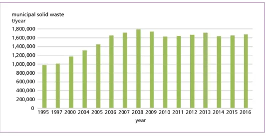
The total quantity of generated municipal solid waste in 2016 was 1,679,765 tonnes [15]. Annual quantities of reported municipal solid waste for the period from 1995 to 2016 are shown in Figure 1 [14, 15].
Figure 1: Annual quantities of generated municipal solid waste (MSW) in the Republic of Croatia during the period from 1995 to 2016
Sources: Croatian Agency for Environment and Nature (2016): Municipal Waste Report for 2015, MWR. Zagreb: CAEN.;
Croatian Agency for Environment and Nature (2017): Municipal Waste Report for 2016, MWR. Zagreb: CAEN 0
200,000 400,000 600,000 800,000 1,000,000 1,200,000 1,400,000 1,600,000
1995 1997 2000 2004 2005 2006 2007 2008 2009 2010 2011 2012 2013 2014 2015 2016 year
municipal solid waste t/year
1,800,000
MBT and SRF
When observing the quantities of generated MSW as far as their origin (county) is con- cerned, a discrepancy between continental and coastal counties or regions has to be noted, mostly due to the effect of tourism. Besides this effects of tourism, the deviations from average quantities of waste that can be noted in some counties, municipalities and cities may be caused additionally by not weighing the waste accurately, which often results in undervalued estimations of the quantities of waste received at local landfills [22].
1.2. Recycling rate of MSW
The recycling rate for MSW was 18 % in 2015 and 21 % in 2016. In Croatia, no energy recovery or incineration of MSW is applied, that means, most of the MSW, i.e. 79 % in 2016, was landfilled without any pre-treatment prior to disposal. This performance development for the period 2006 to 2016 is shown in Figure 2 by applying the RIL- Ternary Diagram Method [29].
1.3. Mixed municipal solid waste
The present contribution deals with mechanical biological waste treatment (MBT) plants in the Republic of Croatia, and as in Croatia it is planned to treat mixed municipal solid waste (MMSW) in so-called waste management centres, additional comprehensive data on MMSW is given in this subchapter.
Mixed municipal solid waste is waste from households and waste from stores, industry and institutions, which in its properties and composition is similar to household waste, that has not been subjected to special procedures of extraction of certain materials (e.g.
paper and glass), and carries the code 20 03 01 in the Croatian Waste Catalogue [17].
Mixed municipal waste is representing the main waste type of MSW, in total 1,262,844 tonnes out of 1,653,918 tonnes MSW corresponding to 76.4 % were generated in 2015 [13].
In 2016, 1,251,299 tonnes MMSW out of 1,679,765 tonnes MSW, or 74.5 % were generated [15]. The evaluated MMSW materials composition in the RC for 2015 is shown in Figure 3.
Figure 2:
Presentation of Croatian MSW performance development by using the RIL-Ternary Diagram Method, data from 2006-2016
Source: Pomberger, R.; Sarc, R.; Lorber, K. E. (2017): Dynamic visualisation of municipal waste management perfor- mance in the EU using Ternary Diagram method. Waste Management 61, 558-571 20152016
2013 2010 2006
incineration %
landfill % recycling %
0
0 0
10
10 10
20
20 20
30
30 30
40
40 40
50 50 50
60 60
60
70 70
70
80 80
80
90 90
90
100 100
100
MBT and SRF
kitchen waste 30.9 % plastic
22.9 %
paper and cardboard 23.2 % other waste (soil, dust, sand)
6.3 %
metal 2.1 % skin/bones 0.5 % rubber 0.2 % glass 3.7%
garden waste 5.7 % textile/clothing 3.7 %
wood 1.0 %
Figure 3: Evaluated composition of mixed municipal solid waste in the RC in 2015
Source: Government of the Republic of Croatia (2017): Waste Management Plan of the Republic of Croatia for the period 2017-2022, WMP. Zagreb: GRC
1.4. Treatment of mixed municipal solid waste
The WMP of the Republic of Croatia in the period from 2007 to 2015 [21] foresaw the construction of 13 regional waste management centres (WMCs) for treatment of mixed municipal solid waste and other waste that is not directly recyclable (Figure 4). In 2017, the number of WMCs was revised and according to the decision of the Croatian government, eleven WMC should be built, only [33].
Figure 4: Position of planned WMCs according to the WMP of the Republic of Croatia for the period 2007-2015 and con- sidering the status of realization in 2016; based on the decision of the Croatian government eleven centres were confirmed in 2017 only; i.e. WMCs Tarno and Doline will not be built
Sources: Government of the Republic of Croatia (2017): Waste Management Plan of the Republic of Croatia for the period 2017-2022, WMP. Zagreb: GRC.;
Vlada Republike Hrvatske (2017) Odluka o implementaciji Plana gospodarenja otpadom Republike Hrvatske za razdo- blje 2017.-2022. godine [Decision of the government on implementation of the national waste management plan for the period 2017 – 2022]
waste management centres project relation status
built in construction
preparation of documentation for EU cofunding projects is underway preparation of documentation for EU cofunding is not yet underway Kastijun
Marscina Babina Gora
Biljane Donje Bikarac
Lecevica
Lucino Sagulje
Orlovnjak Doline
Piskornica Zagreb
Tarno
MBT and SRF
The waste treatment technology/technologies in the WMCs was/were not clearly defined in the plan, but technology and capacities for each plant and location were/are intended to be defined based on the results of feasibility studies considering economic, ecological, and social aspects [21]. WMCs do not only consist of MBT or Waste-to-Energy (WtE) plants as treatment technologies, but also includes recycling yards, treatment areas for construction and demolition waste, landfill areas for various stable and/or inert non- hazardous wastes, waste water treatment plants etc.
As shown in Figure 4, up to now (June 2018), two WMCs, namely WMC Kaštijun, with a 90,000 t/a capacity (in: County of Istria) and WMC Marišćina, with a 100,000 t/a capacity (in: County of Primorje-Gorski Kotar) have been realized so far and are in operation (Figure 5). In addition to the public WMCs, one private MBT facility in the city of Varaždin (95,000 t/a, located in north-west Croatia) is operated too.
a) WMC Marišćina – MBT plant: Input waste bunker and waste shredding prior biological waste treatment (drying) in boxes
b) WMC Kaštijun – weight bridges (right) and main office building (left)
c) WMC Kaštijun – photo left: recycling yard and MBT plant (behind);
photo right: bioreactor landfill compartments
Figure 5:
Photo-documentation of WMC Marišćina and WMC Kaštijun (status: May 2018)
MBT and SRF
1.5. Waste-to-Energy in Croatia
As already mentioned, no WtE plants for MSW are operating in Croatia. Currently, one private company has a suitable location and a valid (construction) permit for a WtE plant. Based on the available data, company C.I.O.S. Energy owns this permit at location Sisak with a planned capacity of 24,000 tonnes of refuse derived fuels (RDFs) per year. Depending on the chosen technology, the time for completing the works ranges from six months up to two years [18].
In the WMP 2017 to 2022 no detailed information about WtE plants in Croatia is given, but based on the local (market) information, at least one WtE plant will be built (in Zagreb) with an annual capacity of 300,000 to 400,000 tonnes MMSW or RDF including SRF as well as sewage sludge.
As reported by the European Commission’s Joint Research Centre (JRC) in mid-2015, the Croatian potential for waste incineration after 2018 will be at least 1 million t/a if Croatia follows the European best practice in waste management. Besides the waste incineration capacities in three existing cement plants (Cemex, Holcim, Nexe), accor- ding to two scenarios suggested by the JRC, Croatia will have to build additional two to four WtE plants with a size between 153,000 and 465,000 t/a, if the full potential will be used [24]. Under the first option (Figure 6), Croatia’s three cement plants could increase waste substitution rate to 50 %, i.e. energy recovery of 364,000 t/a, and only two WtE facilities would be needed then [24]:
• Zagreb: 465,000 t/a combined heat and power (CHP) plant, including sewage sludge firing,
• Zadar: 172,000 t/a power plant.
Figure 6:
Scenario 1: Cement kilns ope- ration with 50 % of energy from waste
Source: Joint Research Centre (2015):
Analysis of Croatian Potentials of Muni- cipal Solid Waste for Bioenergy. Vienna:
JRC energy recovery from waste
waste management centre
cement factory CHP
CHP
EO EO
Zagreb 415,000 t/y Nexe 98,000 t/y Holcim 109,000 t/y Zadar 172,000 t/y Cemex 166,000 t/y
* CHP = combined heat and power EO = electricity only
MBT and SRF
As for the second option (Figure 7), cement industry substitutes 29 %, i.e. 209,000 t/a, of energy with waste and four WtE plants would be needed [24]:
• Zagreb: 325,000 t/a CHP,
• Osijek: 153,000 t/a CHP,
• Rijeka: 177,000 t/a power plant,
• Split: 280,000 t/a power plant.
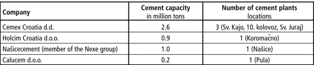
1.6. Co-Incineration in cement industry in Croatia
The Croatian cement industry consists of four cement companies: Cemex Croatia d.d. in Kaštel Sućurac, Holcim Croatia d.o.o. in Koromačno, Našicecement d.d. in Našice and Calucem d.o.o. in Pula. The first three are portland cement producers, while Calucem produces aluminous cement (Table 1) [15].
Figure 7:
Scenario 2: Cement kilns ope- ration with maximum 29 % of energy from waste
Source: Joint Research Centre (2015):
Analysis of Croatian Potentials of Muni- cipal Solid Waste for Bioenergy. Vienna:
JRC
Table 1: Cement plants and their production capacities in Croatia
Company Cement capacity Number of cement plants
in million tons locations
Cemex Croatia d.d. 2.6 3 (Sv. Kajo, 10. kolovoz, Sv. Juraj)
Holcim Croatia d.o.o. 0.9 1 (Koromacno)
Našicecement (member of the Nexe group) 1.0 1 (Našice)
Calucem d.o.o. 0.2 1 (Pula)
Sources: CEMEX Croatia: Sustainable Development Report for 2015 and 2016
Rašić Jelavić, S.; Brkić, I.; Kožul, A.: Financijski pokazatelji cementne industrije u Hrvatskoj [Financial key figures of cement industry in Croatia]. Ekonosmka misao i praksa 2, 565-586, 2016
Našicecement d.d.: Annual consolidated NEXE Group report for 2016
Calucem: Summary for informing the public – Request for determination of integrated environmental protection conditions for existing Calucem d.o.o. plant, 2013
ˇ
waste management centre cement factory energy recovery from waste
WtE-plant waste management centre
cement factory CHP
CHP CHP
CHP EO CHP
EO
EO
EO waste coverage
Zagreb 352,000 t/y
Nexe 53,000 t/y Holcim 61,000 t/y Cemex 95,000 t/y Osijek 153,000 t/y Rijeka 177,000 t/y Split 280,000 t/y
* CHP = combined heat and power EO = electricity only
MBT and SRF
In Croatian cement industry, various refuse derived fuels (RDFs) are used for energy recovery, like scrap tyres, SRF from non-hazardous waste, waste oil etc. The average thermal substitution rate (TSR) in 2017 was below ten percent [23]. All cement kilns operated in Croatia currently have the technical possibility to use SRF Premium, i.e.
Hu > 18 MJ/kgOS and d95 < 30 (35) mm, at the primary burner only. No kiln is equipped with a secondary firing system yet.
Based on the before mentioned EC-JRC investigation [24], the total annual energy consumption of the Croatian cement industry is 7,600 TJ. Malbasa [26] reports a total annual energy consumption of 9,000 TJ and Sarc [31] of 12,300 TJ.
That means, there is a SRF potential for co-incineration in the Croatian cement industry between 211,000 t/a, i.e. 29 % TSR, and 360,000 t/a, i.e. 50 % TSR [24]. In his newest investigations, i.e. assumptions and calculations, Malbasa [26] reports as follows: If 30 % of the energy demand of Croatian cement plants is realized with SRF, this would mean a consumption of about 2,700 TJ/year from waste or about 153,000 tonnes per year of waste fuel, i.e. average heating value is 17,6 MJ/kgOS. Since it has been shown in investigations that the production of waste fuel from MMSW could be between 340,000 and 460,000 tonnes per year, it follows that in the cement industry, a maximum thermal substitution rate of fuel generated from waste would be between 33 % and 45 % [26]. Sarc [31] reports that in case of a clinker capacity utilisation rate of 75 % (data for 2015) and by considering 20 % TSR in primary firing system by using SRF Premium, i.e. Hu =19,3 MJ/kgOS, about 95,000 tonnes of SRF per year would be required. Additionally, if secondary firing systems would be installed in all plants, for reaching 30 % TSR in the secondary firing system by using SRF Medium, i.e. Hu =15,5 MJ/kgOS, 180,000 tonnes SRF per year would be needed. In total, to reach 50 % TSR, 275,000 tonnes of SRF are required.
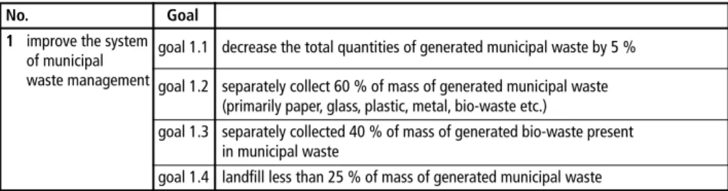
1.7. Further goals and priorities according to the WM Plan 2017 to 2022
As already mentioned before, the Material Recycling Rate for MSW was 21 % in 2016.
According to the current legislative [1] RC has to achieve 50 % Recycling Rate by 2020. In the WM Plan 2017-2022, among others, goals for improving municipal waste management are given (Table 2).
Table 2: Part 1 – Waste management goals that need to be met by 2022 according to the actual WMP 2017 to 2022
No. Goal
1 improve the system goal 1.1 decrease the total quantities of generated municipal waste by 5 % of municipal
waste management goal 1.2 separately collect 60 % of mass of generated municipal waste (primarily paper, glass, plastic, metal, bio-waste etc.)
goal 1.3 separately collected 40 % of mass of generated bio-waste present
in municipal waste
goal 1.4 landfill less than 25 % of mass of generated municipal waste
MBT and SRF
2. Materials and methods
A comprehensive investigation was carried out on the characterization of one type of SRF, namely (fine) SRF Premium Quality (basic properties: Hu > 18 MJ/kgOS and d95< 30 (35) mm and usually utilized at primary burner in cement industry only), during about four months (March to June 2018). In total, SRF from three Croatian MBT plants that are in operation has been extensively investigated by sieving analyses, as well as chemical-physical analyses. SRF from C.I.O.S. plant is subjected only to chemical-phy- sical characterization, while for SRF from WMC Marišćina and Kaštijun (using MMSW only) additional to the chemical-physical analyses, sieving analyses have been carried out too. For the elaboration of a sampling concept for representative sampling of SRF from the storage depot, particle size (d95), bulk density (kg/m3), and other parameters according to the ÖNORM EN 15442 have been applied. Sampling was carried out in every SRF production plant with a total field sample amount between 5 to 22 kg. Then, based on ÖNORM 15415-1, sieving analyses of both before mentioned SRF samples were performed. Finally, the samples were first dried at 40 °C (required, because of the determination of Hg content) and at 105 °C again and extensive physical-chemical investigations were carried out at the accredited laboratory of the Chair of Waste Pro- cessing Technology and Waste Management at the Montanuniversitaet Leoben. Based on the data gained and other relevant data reported in literature, comparisons have been carried out and are presented in the next chapter. Sampling plan, procedure of analyses and investigation are according to the (international) standards (e.g. ÖNORM EN 15442) and national regulations reported and discussed in Sarc et al. [32].
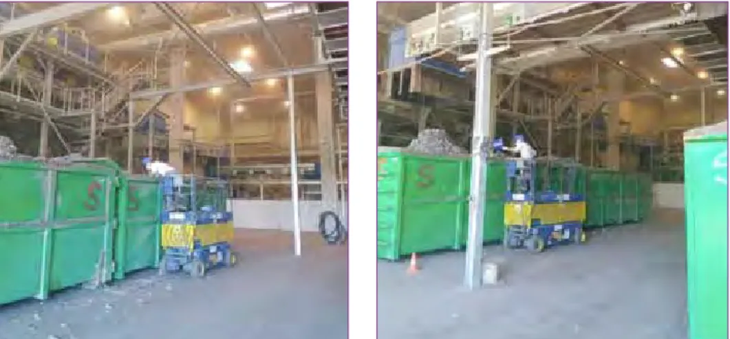
For the benefit of visual characterisation, a photo documentation of a sampling pro- cedure in one of the investigated MBT plants is shown in Figure 8.
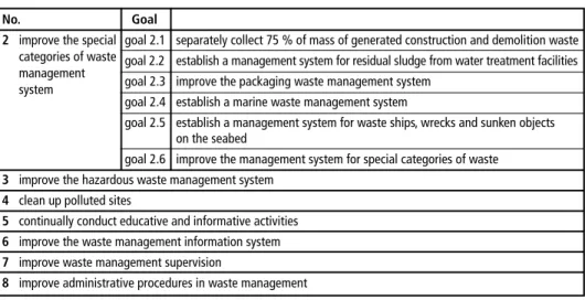
Table 2: Part 1 – Waste management goals that need to be met by 2022 according to the actual Waste Management Plan 2017 to 2022
No. Goal
2 improve the special goal 2.1 separately collect 75 % of mass of generated construction and demolition waste categories of waste goal 2.2 establish a management system for residual sludge from water treatment facilities
management
goal 2.3 improve the packaging waste management system system
goal 2.4 establish a marine waste management system
goal 2.5 establish a management system for waste ships, wrecks and sunken objects
on the seabed
goal 2.6 improve the management system for special categories of waste 3 improve the hazardous waste management system
4 clean up polluted sites
5 continually conduct educative and informative activities 6 improve the waste management information system 7 improve waste management supervision
8 improve administrative procedures in waste management
Source: Government of the Republic of Croatia: Waste Management Plan of the Republic of Croatia for the period 2017-2022, WMP. Zagreb: GRC, 2017
MBT and SRF
Figure 8: Own photo-documentation as an example of one sampling procedure during the inves- tigation reported
3. Results and discussion
As already described, the samples taken from the fuel storage of different waste proces- sing plants have been comprehensively investigated and analysed and some summarized results are presented here.
3.1. Input waste materials for production of SRF
In Table 3, input waste materials for SRF production in three different Croatian MBT plants are summarized. The input waste materials that are treated in the processing plants can be described by their waste code in accordance with the European List of Waste [19].
MBT in WMC Kaštijun
20_03_01 mixed municipal waste MBT in WMC Marišcina
20_03_01 mixed municipal waste MBT plant C.I.O.S. Varaždin
04_02_99 wastes from the textile industry not otherwise specified 20_03_01 mixed municipal waste, etc...
and various other municipal and industrial waste types
´
Table 3:
Input waste materials for Croatian MBT plants
3.2. Output waste materials from MBT plants
The output produced SRF is legally not considered as a product but still as a waste, classified by two waste codes:
• 19_12_10: (quality assured) combustible waste, i.e. SRF, and
• 19_12_12: other wastes from mechanical treatment of wastes, i.e. RDF.
MBT and SRF
3.3. Applied technology
Here, applied technology and treatment concepts of all three plants are presented.
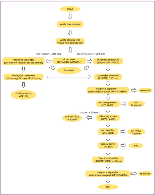
3.3.1. MBT Varaždin In the MBT C.I.O.S. MBO d.o.o. Varaždin, not only mixed municipal waste, but also non-hazardous industrial waste is treated. Hereafter, a short technical description is given, and a SRF production scheme is shown in Figure 9.
Waste receivement After weighing, waste inspection and documents checking, the delivered municipal and non-hazardous industrial waste is transported to the MBT plant. There, the waste is unloaded in the original state through the hall door into the waste receiving pits.
Mechanical pretreatment Pretreatment of waste includes a mechanical treatment of waste, i.e. a whole series of sieving, separation and other processing steps. In this technological process, the waste is separated into two fractions, i.e. a fine (< 200 mm) and a coarse fraction (> 200 mm).
The fine fraction undergoes biological treatment, and the coarse fraction is transported to further mechanical treatment. Prior to biological treatment, magnetic materials, such as iron alloys, are separated by using a magnetic separator.
Biological treatment After mechanical pretreatment, the smaller fractions are transferred to a section of the biological treatment plant where they are being processed, i.e. biodried, one to three weeks, depending on the given input or required output parameters of different fractions. By aerobic biodrying of organic waste fractions, the waste becomes easier to handle – lower water content and better processing properties – for the following mechanical treatment.
Mechanical treatment In the mechanical processing area, once again potentially remaining metal portions are removed from the waste. Then, the waste is transported to the non Fe-separating unit. Afterwards, the waste is transferred to the vibrating screen that separates the small fraction (particle size < 25 mm) from the coarse waste, which then is transported through the conveyor to the foreseen container. After passing through the vibrating screen, the waste is conveyed into an air classifier which separates the interfering heavy fraction (e.g. stones, concrete, glass). The remaining waste is transported to the NIR infrared separator system where different types of waste materials can be separated (e.g. PET, PVC). Once again, any residual metals are removed and finally, the remaining waste comes to a fine size shredder that comminutes waste, i.e. SRF, to a particle size less than 30 mm.
MBT and SRF
Figure 9: Multistage processing scheme of MBT plant C.I.O.S. MBO d.o.o. Varaždin
Source: C.I.O.S. d.o.o. (2015): Studija o utjecaju na okoliš – Uniprojekt TERRA [Report on environmental assessment analysis], March 2015.
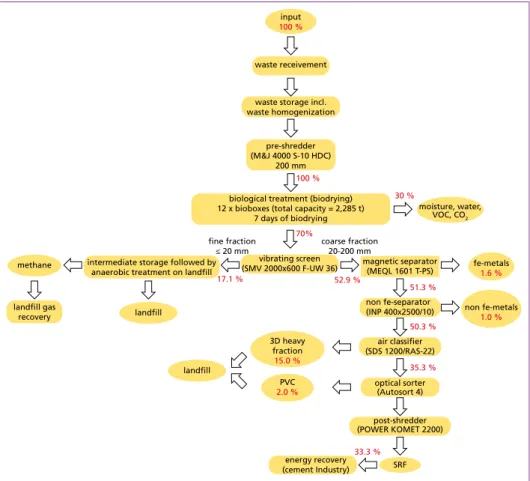
3.3.2. WMC Kaštijun and WMC Marišcina
As both WMCs use the same MBT-technological concept, here a short technical description is given. Additionally, the process scheme and the actual mass balance are shown too (Figure 10 and Figure 11).
input
waste receivement
waste storage incl.
waste homogenization
drum sieve (TROMMEL 60090032)
biological treatment (biodrying) 14 days of biodrying
magnetic separator (electric SEN 1400 C) magnetic separator
(permanent magnet SM-NS SME06)
coarse size shredder (JUPITER) 130 mm
magnetic separator (permanent magnet SM-NS SME06)
non re-separator (ECS 2000)
vibrating screen (SEWU 2400)
air classifier (SDS-1200)
optical sorter (TITECH)
fine size shredder (KOMET 2800) < 30 mm
magnetic separator (permanent magnet SM-NS SME06)
SRF
fe-metals PVC 3D heavy
fraction compost-like
material
non fe-metals
fe-metals moisture water,
VOC, CO2
fe-metals
fraction < 25 mm fine fraction < 200 mm coarse fraction > 200 mm
´
MBT and SRF
Waste receivement The waste receivement takes place at the gate of the centre using an electronic scale, where the following things are recorded:
1) vehicle registration,
2) date and time of arrival of the vehicle,
3) full name of the company which delivers the waste, 4) address of the company,
5) telephone number, and
6) weight of the vehicle obtained by weighing.
Input storage After weighing and documentation checking at the entrance of the Centre, trucks with mixed municipal waste are directed to the receiving pit of MBT plant. The receiving pit is designed in a way that can receive three-day nominal capacity.
Pre-processing before biological treatment Previous processing before biological treatment takes place in the same hall where the waste reception into the receiving pit is organized.
Previous processing involves shredding of the received waste prior to its biological treatment. Waste from the receiving pit is transferred with crane into a shredder, where it is shredded up to 200 mm. The shredder is mounted on a moving bridge and moves to the width of the building. The shredded waste falls into a temporary bunker located beneath the shredder and the moving bridge.
Biological treatment The plant for biological treatment (biodrying) is located in the same hall as the section for waste receivement and pre-processing before biological treatment.
The targets of biodrying are:
1) stabilization and hygienisation of organic matter, 2) water removal, and
3) increasing the waste calorific value.
The biodrying plant uses twelve bioreactors and its loading and unloading is totally automated by means of a process crane.
Shredded waste that needs to biodry is supplied from a temporary bunker. When biological drying is complete, biodryed material of each bioreactor is transported to a roller conveyor, which is equipped with a loading funnel. The roller conveyor doses the waste into the attached mechanical treatment section.
Pre-procedures/processing before disposal/recovery In the mechanical section, a number of devices/machines are used to separate different fractions of input waste such as waste fuel, metals, plastics, heavy interfering fraction and so-called methanogenic fraction, suitable for the production of biogas.
MBT and SRF
Output storage
After the process of mechanical-biological treatment is done, various waste fractions, i.e. processing products, are stored separately according to their properties and type in the section of the hall intended for mechanical treatment.
Disposal of compost like output (CLO)
Dried mixed municipal solid waste, which has undergone the process of mechanical- biological treatment at the MBT plant, is disposed of within the centre on the landfill provided for the disposal of the methanogenic fraction, i.e. compost like output (CLO).
In stabilized form, this fraction undergoes intermediate storage, before it is finally anaerobic decomposed at landfill.
Energy recovery of SRF
SRF produced at site is used in the cement industry as quality controlled alternative fuel.
Valuable separated metals
Ferrous and non-ferrous metals are handed over to an authorized collector for recycling.
Figure 10: Multistage processing scheme with mass balance of the MBT plant at the WMC Kaštijun
Source: Kaštijun (2018): Personal information on 18.5.2018.
input
waste receivement
waste storage incl.
waste homogenization
pre-shredder (M&J 4000 S-10 HDC)
200 mm
biological treatment (biodrying) 12 x bioboxes (total capacity = 2,285 t)
7 days of biodrying
vibrating screen
(SMV 2000x600 F-UW 36) magnetic separator (MEQL 1601 T-PS) intermediate storage followed by
anaerobic treatment on landfill
landfill gas recovery
non fe-separator (INP 400x2500/10)
air classifier (SDS 1200/RAS-22)
optical sorter (Autosort 4)
post-shredder (POWER KOMET 2200)
SRF 3D heavy
fraction 15.0 % methane
PVC 2.0 %
non fe-metals 1.0 % fe-metals
1.6 %
landfill
landfill fine fraction
≤ 20 mm coarse fraction
20-200 mm 100 %
moisture, water, VOC, CO2
energy recovery (cement Industry)
100 %
70%
30 %
17.1 % 52.9 %
51.3 %
50.3 %
35.3 %
33.3 %
MBT and SRF
Figure 11: Multistage processing scheme with mass balance of the MBT plant at the WMC Marišćina
Source: Marišćina, 2018: Personal information on 18.5.2018.
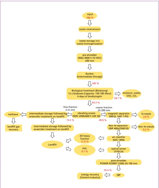
3.4. Results from own investigations
In Figure 12, one of the investigated SRF is depicted. As already noted in Chapter 2, for SRF from C.I.O.S. plants only a chemical-physical characterisation was performed.
For SRF from WMC (using MMSW only) additional to chemical-physical analyses, sieving and sorting analyses have been carried out.
input
waste receivement
waste storage incl.
waste homogenization
pre-shredder (M&J 4000 S-10 HDC)
200 mm
Bunker (Intermediate Storage)
Biological treatment (Biodrying) 12 x bioboxes (capacity: 150-160 t/box)
6 days of biodryingAir
vibrating screen (SMV 2000x600 F-UW 36)
intermediate storage followed by anaerobic treatment on landfill
magnetic separator (MEQL 1601 T-PS) intermediate storage followed by
anaerobic treatment on landfill
landfill gas recovery
Non fe-separator (INP 400x2500/10)
air classifier (SDS 1400)
optical sorter (TITECH)
post-shredder POWER KOMET 2200) 20-100 mm
SRF 3D heavy
fraction 11.5 % methane
PVC 0.1 %
Non fe-metals 0.2 % fe-metals
2.6 %
Landfill
fine fraction
0-25 mm coarse fraction
25-200 mm 100 %
moisture, water, VOC, CO2
energy recovery (Cement Industry)
100 %
65.3 %
34.7 %
15.5 % 49.8 %
35.4 %
MBT and SRF
3.4.1. Results from sieving analyses In total, two SRF (for the benefit of ano- nymity, named as: SRF #1 and SRF #2), where each material is produced in one of the MBT plants described before, have been sampled and analysed. Results from sieving analyses are presented in Figure 13. Sieving analyses were per- formed in accordance with the (inter) national standard ÖNORM 15415-1 [6].
Figure 12: Photo documentation of one inves- tigated SRF
Figure 13: Results from sieving analyses of investigated SRF #1 and SRF #2
As shown in Figure 13, even though SRF is produced in MBT plants that use the same technology concept and having similar performance, differences in particle size (d [mm]) are obvious. The particle size distribution of SRF #1 is much narrower than the one from SRF #2 and only SRF #1 fulfils the technical requirement on particle size (d95 ≤ 30 (35) mm). This observed wider particle size distribution of SRF #2 may be explained by the obvious suboptimal operation of fine shredding machines at the time of SRF sampling. Finally, about 80 % of SRF #2 can reach the particle size of 30 mm that is required when being used for energy recovery in primary burners of cement industry.
0 10 20 30 40 50 60 70 80 90 100
0 2 4 6 8 10 12 14 16 18 20 22 24 26 28 30 32 34 36 38 40 42 44 46 48 50 weight
%
-
particle size mm
SRF #1 SRF #2
MBT and SRF
3.4.2. Results from physical-chemical analyses Three groups of results from the physical-chemical investigations are presented in Table 4. The energy and CO2 emission relevant parameters mainly depend on waste input quality and on technology applied for the processing of SRF. The procedural and mass balance parameters are relevant to the plant and the combustion process. Finally, mass and energy specific heavy metal content, i.e. heavy metal content as product of pollution in mg/kgDM and lower heating value in MJ/kgDM, present values needed for fulfilling Aus- trian legal requirements according to the national Waste Incineration Ordinance (WIO).
Table 4: Results from chemical-physical analyses of investigated SRF
Parameter Unit Austrian Standard (ASI) SRF #1 SRF #2 SRF #3 Energy and CO2 emission relevant parameters
Higher Heating Value HHV MJ/kgDM 22.4 19.9 30.6
Lower Heating Value LHV MJ/kgOS [ASI, 2000] 16.6 14.4 23.8
Lower Heating Value LHV MJ/kgDM 20.6 18.3 28.1
Total Carbon TC %DM – 49.6 46.6 62.9
Biomass Content (related to TC) XBTC w%DM 34.7 52.4 20.7 Non-Biomass Content (related to TC) XnBTC w%DM 65.3 47.6 79.3
Biomass Content XB w%DM [ASI, 2011-2] 38.4 55.2 25.5
Non-Biomass Content XnB w%DM 35.3 22.6 63.1
Non-Biomass Content of total Waste XnBW w%DM calculated 32.4 22.2 49.9
Fossil CO2emission g/MJDM calculated 57.5 44.4 65.0
Procedural and mass balance parameters
Dry Matter DM w% [ASI, 2006] 82.5 81.3 85.8
Ash (815 °C) w%DM [ASI, 1997] 19.4 18.6 11.0
Chlorine Cl g/kgDM [ASI, 2007] 4.8 4.9 7.43
Sulfur S g/kgDM [ASI, 2016] 2.6 3.0 1.3
Energy specific heavy metal content
Antimony Sb mg/MJDM 0.9 1.2 1.5
Arsenic As mg/MJDM 0.1 0.1 0.1
Lead Pb mg/MJDM 4.4 4.6 1.2
Cadmium Cd mg/MJDM 0.026 0.014 0.009
Chromium Cr mg/MJDM [ASI, 2011-3]
2.6 2.1 0.7
Cobalt Co mg/MJDM 0.3 0.3 0.1
Nickel Ni mg/MJDM 0.8 0.8 0.3
Mercury Hg mg/MJDM 0.012 0.014 0.009
Sources: Austrian Standards Institute (1997) Testing of solid fuels – Solid mineral fuels – Determination of ash content, DIN 51719. Vienna: ASI Austrian Standards Institute (2000) Testing of solid and liquid fuels – Determination of gross calorific value by the bomb calorimeter and calculation of net calorific value – Part 1: Principles, apparatus, methods, DIN 51900-1. Vienna: ASI
Austrian Standards Institute (2000) Solid recovered fuels – determination of moisture content using the oven dry method. Part 1: determination of total moisture by a reference method, ÖNORM CEN/TS 15414-1. Vienna: ASI
Austrian Standards Institute (2007) Water quality – Determination of dissolved anions by liquid chromatography of ions - Part 1: Determination of bromide, chloride, fluoride, nitrate, nitrite, phosphate and sulfate, DIN EN ISO 10304-1. Vienna: ASI
Austrian Standards Institute (2011-2) Solid recovered fuels – methods for the determination of biomass content, ÖNORM EN 15440. Vienna: ASI Austrian Standards Institute (2011-3) Solid recovered fuels – methods for the determination of the content of trace elements (As, Ba, Be, Cd, Co, Cr, Cu, Hg, Mo, Mn, Ni, Pb, Se, Tl, V and Zn), ÖNORM EN 15411. Vienna: ASI
Austrian Standards Institute (2016) Characterization of waste – Halogen and sulfur content – Oxygen combustion in closed systems and determi- nation methods, ÖNORM EN 14582. Vienna: ASI
MBT and SRF
These legal requirements are not relevant for the Croatian SRF situation, but for the benefit of better understanding the SRF quality, this comparison is shown in the present contribution (Figure 14).
As shown in Table 4, when comparing SRF #1 and SRF #2 with SRF #3, higher heating value (HHV) and lower heating value (LHV) of MJ/kgOS and LHV in MJ/kgDM are much lower in case of SRF #1 and #2 because the MBT plant producing SRF #3 also uses high calorific non-hazardous industrial waste besides mixed municipal waste.
The calculation of CO2 emissions (complete combustion, i.e. 1 g Cfossil = 3.66 gCO2 emission) shows that the emissions from SRF produced out of MMSW are 44.4 g/MJDM (for SRF #2) and 57.5 g/MJDM (for SRF #1). SRF #3 shows much higher fossil CO2 emissions compared to the other two SRF, and as shown, there is a clear correlation between higher heating value and higher fossil CO2 emission – extensively discussed in Sarc et al. [32].
The water content as well as the ash content are generally below 20 % for all SRF inves- tigated (required market values between 15 % and 20 %). Chlorine content is below the international limit for cement industry, i.e. 1 %OS.
Figure 14 shows the heavy metals investigated according to the international standard and compared to the limit values from Austrian WIO for SRF used in the cement industry.
0 10 20 30 40 50 60 70 80 90 100
Sb Cd Hg Pb Cr Co Ni As
SRF #1 SRF #2 SRF #3
exhaustion of WIO – limit values
%
Figure 14: Heavy metals in SRF #1, SRF #2 and SRF #3 compared to Austrian WIO 80th percentile limit values that are set 100 % (further explanation of the comparison in [32])
Sources: Sarc, R.; Lorber, K. E.; Pomberger R.; Rogetzer, M.; Sipple, E. M. (2014): Design, quality, and quality assurance of solid recovered fuels for the substitution of fossil feedstock in the cement industry. Waste Management & Research 32 (7), 565-585
From Figure 14, it becomes obvious that the chemical quality, i.e. heavy metals content, of currently used SRF in Croatia easily fulfils the Austrian legal limit values for co- incineration in the cement industry and that their quality is in the same range as the SRF utilized on the Austrian market [32]. The reported results on the physical-chemical composition of SRF are representative for the current Croatian SRF quality available on the waste to energy market.
MBT and SRF
4. Conclusions
In the Republic of Croatia, the current status in waste management is presented in the WMP for the period 2017 to 2022 [22], a national document that introduces the current state and contains an action plan with aims and measures for further waste management development up to 2022, already considering selected targets of the new Circular Economy Package [20]. According to this document, in 2014 total reported quantities of generated solid waste (municipal and production waste) were around 3.7 million tonnes.
Total quantity of generated municipal solid waste (MSW) in 2016 was 1,679,765 ton- nes [15]. Mixed municipal solid waste (MMSW) is representing the main waste type of municipal waste, in total 1,262,844 tonnes out of 1,653,918 tonnes MSW or 76.4 % were generated in 2015 [13]. In 2016 1,251,299 tonnes MMSW out of 1,679,765 tonnes MSW, or 74.5 % were generated [15]. Material Recycling rate for MSW was 18 % for 2015 and 21 % for 2016. In Croatia, no energy recovery or incineration of MSW is applied so far, that means, most of the MSW, i.e. 79 % in 2016, was landfilled without any pre-treatment prior to disposal.
According to the WMP for the period 2007 to 2015, 13 so called WMCs were planned.
In 2017, number of WMCs was revised and according to the decision of the Croatian government, eleven WMC should be built. WMCs do not only consist of MBT or WtE plants as a treatment technology, but also contain recycling yards, treatment areas for construction and demolition waste, landfill areas for various stable and/or inert non-hazardous wastes, waste water treatment plants. Currently, two WMCs with MBT technology for MMSW and one private owned MBT plant are in operation with a total capacity of 285,000 tonnes per year. No WtE plants for municipal waste are in operation so far and the average TSR for energy recovery of RDF in Croatian cement industry was reported below 10 % in 2017. All cement kilns operating in Croatia have currently the technical possibility to use SRF Premium, i.e. Hu > 18 MJ/kgOS and d95< 30 (35) mm, at primary burner only. No kiln is equipped with secondary firing system yet. Both, WtE plants and further development of TSR in cement industry have certain potential in Croatia. It is expected, that two to four WtE plants will be built in the next years. Additionally, about 200,000 to 300,000 t/a SRF may be utilized in the Croatian cement industry.
As described in this paper, a comprehensive investigation was carried out on the characterization of one type of SRF, namely Croatian SRF Premium Quality that usu- ally is utilized for energy recovery in cement industry. Both WMCs are in operation since several months and one privately owned MBT since several years and all three plants produce SRF too. Their technical design and function (Figure 9, Figure 10 and Figure 11) is comparable to the technical concepts and standards of MBTs in other EU countries. The quality of all three investigated SRF, as shown in Table 4 and Figure 14, is comparable with the quality of Austrian SRF investigated and reported in Sarc et al.
[32]. By considering Austrian limit values (expressed in % exhaustion) for heavy metals in SRF before co-incineration, the exhaustion of limit values by heavy metal contents
MBT and SRF
of Croatian SRF is below 20 %, (Figure 14). Finally, it can be confirmed and stated that SRF produced in Croatian MBT plants is in fact the SRF Premium Quality that can be traded on the European SRF market and utilized in the European cement industry.
Acknowledgement and funding
The authors are very grateful to the C.I.O.S. MBO d.o.o, ŽCGO Kaštijun, ŽCGO Marišćina, and the Croatian cement industry for enabling our investigations of SRF and supporting us with information about waste treatment plants and technology applied as well as market capacities. Many thanks also to our colleagues and co-workers of the Chair’s laboratory, who were responsible for the analytical investigations.
Partial funding for this work was provided by:
The Austrian Centre of Competence for Recycling and Recovery of Waste 4.0 (acronym ReWaste4.0) (contract number 860 884) under the scope of the COMET – Competence Centers for Excellent Technologies – financially supported by BMVIT, BMWFW, and the federal states of Styria, managed by the FFG.
5. References
[1] Act on Sustainable Waste Management (2013): Narodne novine 94/2013 – Zakon o održivom gospodarenju otpadom, Zagreb, Croatia
[2] Austrian Standards Institute (1997): Testing of solid fuels – Solid mineral fuels – Determination of ash content, DIN 51719. Vienna: ASI
[3] Austrian Standards Institute (2000): Testing of solid and liquid fuels – Determination of gross calorific value by the bomb calorimeter and calculation of net calorific value – Part 1: Principles, apparatus, methods, DIN 51900-1. Vienna: ASI
[4] Austrian Standards Institute (2006): Solid recovered fuels – determination of moisture content using the oven dry method. Part 1: determination of total moisture by a reference method, ÖNORM CEN/TS 15414-1. Vienna: ASI
[5] Austrian Standards Institute (2007): Water quality – Determination of dissolved anions by liquid chromatography of ions – Part 1: Determination of bromide, chloride, fluoride, nitrate, nitrite, phosphate and sulfate, DIN EN ISO 10304-1. Vienna: ASI
[6] ASI (Austrian Standards Institute) (ed.) (2011-1): ÖNORM EN 15415-1-Solid Recovered Fuels- Determination of particle size distribution-Part 1: Screen method for small dimension particles.
Vienna, Austria: ASI
[7] Austrian Standards Institute (2011-2): Solid recovered fuels – methods for the determination of biomass content, ÖNORM EN 15440. Vienna: ASI
[8] Austrian Standards Institute (2011-3): Solid recovered fuels – methods for the determination of the content of trace elements (As, Ba, Be, Cd, Co, Cr, Cu, Hg, Mo, Mn, Ni, Pb, Se, Tl, V and Zn), ÖNORM EN 15411. Vienna: ASI
[9] Austrian Standards Institute (2016): Characterization of waste – Halogen and sulfur content – Oxygen combustion in closed systems and determination methods, ÖNORM EN 14582. Vienna:
ASI
[10] BMLFUW (Bundesministerium für Land- und Forstwirtschaft, Umwelt und Wasserwirtschaft) (ed.) (2010): Verordnung über die Verbrennung von Abfällen Abfallverbrennungsverordnung – AVV [Waste Incineration Ordinance]. Vienna, Austria: BMLFUW
MBT and SRF [11] Calucem (2013): Summary for informing the public – Request for determination of integrated
environmental protection conditions for existing Calucem d.o.o. plant [12] CEMEX Croatia (2017): Sustainable Development Report for 2015 and 2016.
[13] C.I.O.S. d.o.o. (2015): Studija o utjecaju na okoliš – Uniprojekt TERRA [Report on environmental assessment analysis], March 2015
[14] Croatian Agency for Environment and Nature (2016): Municipal Waste Report for 2015, MWR.
Zagreb: CAEN
[15] Croatian Agency for Environment and Nature (2017): Municipal Waste Report for 2016, MWR.
Zagreb: CAEN
[16] Croatia cement (2018): web page: http://www.croatiacement.hr/hr/industrija-cementa-u-rh.
php. (May, 2018)
[17] Croatian Ministry of Environment and Energy (2013): Ordinance on the waste catalogue, OG 90/15, OWC. Zagreb: MEE
[18] Energy recovery of waste – C.I.O.S. group (2018): Information in TehnoEko 75, Nr. 3/2018 [19] Environmental Protection Agency (2002): European waste catalogue and hazardous waste list.
Ireland: EPA
[20] European Commission (2018): Circular Economy package, CEP. Brussels, Belgium
[21] Government of the Republic of Croatia (2007): Waste Management Plan of the Republic of Croatia for the period 2007-2015, WMP. Zagreb: GRC
[22] Government of the Republic of Croatia (2017): Waste Management Plan of the Republic of Croatia for the period 2017-2022, WMP. Zagreb: GRC
[23] Holcim: Personal information on 18.5.2018
[24] Joint Research Centre (2015): Analysis of Croatian Potentials of Municipal Solid Waste for Bioenergy. Vienna: JRC
[25] Kaštijun (2018): Personal information on 18.5.2018
[26] Malbaša, N. (2018): Osnove opravdanosti izgradnje energane na gorivo iz otpada (E-GIO) u Hr- vatskoj [Basic eligibility for construction of waste to energy plant for SRF in Croatia]. TehnoEko conference, June 6th-8th 2018, Poreč, Croatia
[27] Marišćina, 2018: Personal information on 18.5.2018
[28] Našicecement d.d. (2017): Annual consolidated NEXE Group report for 2016
[29] Pomberger, R.; Sarc, R.; Lorber, K. E. (2017): Dynamic visualisation of municipal waste manage- ment performance in the EU using Ternary Diagram method. Waste Management 61, 558-571 [30] Rašić Jelavić, S.; Brkić, I.; Kožul, A. (2016): Financijski pokazatelji cementne industrije u Hrvats- koj [Financial key figures of cement industry in Croatia]. Ekonosmka misao i praksa 2, 565-586 [31] Sarc, R. (2015): Procjena potencijala goriva iz komunalnog otpada u Republici Hrvatskoj u kon- tekstu strategije niskougljicnog razvoja. Radionica – Strategija niskougljicnog razvoja Republike Hrvatske [Estimation of SRF potential from municipal waste in Croatia in context of the national low carbon development strategy. Workshop – Low carbon development strategy of Republic of Croatia]. July 3rd 2015, Zagreb, Croatia
[32] Sarc, R.; Lorber, K. E.; Pomberger R.; Rogetzer, M.; Sipple, E. M. (2014): Design, quality, and quality assurance of solid recovered fuels for the substitution of fossil feedstock in the cement industry. Waste Management & Research 32 (7), 565-585
[33] Vlada Republike Hrvatske (2017): Odluka o implementaciji Plana gospodarenja otpadom Repu- blike Hrvatske za razdoblje 2017.-2022. godine [Decision of the government on implementation of the national waste management plan for the period 2017 – 2022]
MBT and SRF
Contact Person
Dipl.-Ing. Dr. mont. Renato Sarc Montanuniversitaet Leoben
Chair of Waste Processing Technology and Waste Management Deputy of the Chair
Franz-Josef-Straße 18 8700 Leoben
AUSTRIA
Phone: 00 43 - 38 42 4 02 51 05 Email: renato.sarc@unileoben.ac.at
Other Institutions
Ministry of Environment and Energy, Zagreb, Croatia University of Zagreb, Faculty of Chemical Engineering and Technology, Zagreb, Croatia
Bibliografische Information der Deutschen Nationalbibliothek Die Deutsche Nationalbibliothek verzeichnet diese Publikation in der Deutschen Nationalbibliografie; detaillierte bibliografische Daten sind im Internet über http://dnb.dnb.de abrufbar
Thiel, S.; Thomé-Kozmiensky, E.; Winter, F.; Juchelková, D. (Eds.):
Waste Management, Volume 8 – Waste-to-Energy –
ISBN 978-3-944310-42-8 Thomé-Kozmiensky Verlag GmbH
Copyright: Elisabeth Thomé-Kozmiensky, M.Sc., Dr.-Ing. Stephanie Thiel All rights reserved
Publisher: Thomé-Kozmiensky Verlag GmbH • Neuruppin 2018 Editorial office: Dr.-Ing. Stephanie Thiel, Dr.-Ing. Olaf Holm,
Elisabeth Thomé-Kozmiensky, M.Sc.
Layout: Janin Burbott-Seidel, Ginette Teske, Roland Richter, Cordula Müller, Sarah Pietsch, Gabi Spiegel, Lena Bischkopf
Printing: Universal Medien GmbH, Munich
This work is protected by copyright. The rights founded by this, particularly those of translation, reprinting, lecturing, extraction of illustrations and tables, broadcasting, micro- filming or reproduction by other means and storing in a retrieval system, remain reserved, even for exploitation only of excerpts. Reproduction of this work or of part of this work, also in individual cases, is only permissible within the limits of the legal provisions of the copyright law of the Federal Republic of Germany from 9 September 1965 in the currently valid revision. There is a fundamental duty to pay for this. Infringements are subject to the penal provisions of the copyright law.
The repeating of commonly used names, trade names, goods descriptions etc. in this work does not permit, even without specific mention, the assumption that such names are to be considered free under the terms of the law concerning goods descriptions and trade mark protection and can thus be used by anyone.
Should reference be made in this work, directly or indirectly, to laws, regulations or guide- lines, e.g. DIN, VDI, VDE, VGB, or these are quoted from, then the publisher cannot ac- cept any guarantee for correctness, completeness or currency. It is recommended to refer to the complete regulations or guidelines in their currently valid versions if required for ones own work.