29th International Cosmic Ray Conference Pune (2005) 00, 101–106
Development and first results of the MAGIC central pixel system for optical observations.
F. Lucarelli
, P. Antoranz , M. Asensio
, J.A. Barrio , M. Camara , J.L. Contreras , R. de los Reyes , M.V. Fonseca , M. Lopez , J.M. Miranda
, I. Oya for the MAGIC collaboration.
(a) Dpto. F´ısica Atomica, Facultad de Ciencias F´ısicas, Universidad Complutense, 28040 Madrid, Spain.
(b) Dpto. F´ısica Aplicada III, Facultad de Ciencias F´ısicas, Universidad Complutense, 28040 Madrid, Spain.
(c) Dept. Infra., I. Sistemas Aeroespaciales y Aerop., Universidad Politcnica, 28040 Madrid, Spain.
(d) Now at the Dip. di Fisica, Universit`a degli Studi di Roma “La Sapienza”, Ple. Aldo Moro 5, 00185 Roma, Italy.
Presenter: F. Lucarelli (lucarel@gae.ucm.es), spa-lucarelli-F-abs1-og27-poster
The MAGIC telescope has been designed for the observation of the ˇCerenkov light generated in Extensive Air Showers. However, its 17 m. diameter and optical design makes it suitable for optical observations as well. In this work, we report on the development of a system based on the use of a dedicated photo-multiplier (PMT) for optical observations installed at the center of the MAGIC camera (the central pixel). An electro-optical system has been developed in order to transmit through optical fiber the PMT output signal to the counting room, where it is digitized and stored for off-line analysis. First tests of this system using the Crab nebula as calibration source show its optical pulsation.
1. Introduction
The MAGIC telescope [1] is an innovative detector aimed to detect very high- energy -rays from astrophysical sources using the Imaging Atmospheric ˇCerenkov technique. The telescope collects the very short flashes of atmospheric ˇCerenkov radiation (5-20 nsec in duration) emitted during the development of the Extended Atmospheric Showers (EAS) produced in the interaction of the cosmic -rays with the atmospheric nuclei.
The main characteristics of the telescope are its 17m. tessellated mirror, a system of analog signal transmission based on optical fiber and signal digital sampling with 300 MHz Flash ADCs. The telescope is especially designed to reach the extremely low energy threshold for primary -rays of 30 GeV. The main detector, or camera, is located at the focus of the telescope and consists of a matrix of 576 fast-response PMTs.
Besides the main -ray observations, the large collection area of the MAGIC telescope can also be used to perform optical observations of varying astronomical objects. That can be done by integrating the slow DC current output of a PMT. This technique was already applied by other ˇCerenkov telescopes (HEGRA CT1 [2], Whipple [3], Celeste [4], HESS [5]) which detected the optical pulsed emission from the Crab pulsar and estimated the photon content of the nebula surrounding the pulsar itself [2].
At commissioning time, the center of the MAGIC camera was deliberately left empty in order to host a dedi- cated PMT for optical observations. Such modified PMT, the so-called central pixel, was installed at the end of March ’05 and tested successfully with the detection of the optical pulsed emission from the Crab pulsar.
In what follows, we will describe the main technical aspects of the installation of the central pixel and the tests performed with the observation of the Crab pulsar.
2. The central pixel
The PMT installed at the center of the MAGIC camera is a standard 1” MAGIC PMT, ET9116 [6], especially designed for fast pulsed-light detection. The DC branch of the pre-amplifier placed at the PMT base has
2 F. Lucarelli et al.
Figure 1. (a) Sketch of the transmission system for the central pixel. (b) Transceiver bandwidth. (c) On-site measurements at La Palma: pulsed signals as received at the end of the transceiver chain in two cases: for a 100 mV input signal at the transmitter (upper plot) and a 10mV input signal (lower plot).
been modified in order to have an integration constant msec. The overall tension was set to 1.08kV, corresponding to a gain of around 20k.
The transmission of the DC output signal from the PMT base to the counting house for its digitalization and storing is made through optical fiber. The electro-optical transceiver (see Fig.1.a) was designed in order to transmit Crab-like signals, that is, analog pulsed signals with 10-100 Hz periods and widths of the order of milliseconds. Thus, instead of the high-speed VCSELs of the MAGIC DAQ chain (which detect the fast Cerenkov pulses), a wide dynamic range LED was used (Honeywell HFE 4050-014 [8]). The optical fiberˇ (a graded index multimode fiber 50/125mm core/cladding, ( =850nm.)) and the connectors (Diamond MAT E-2000) were already installed in the camera. The length of the optical fiber from the camera to the counting house is of about 170m.
At the emitter, the LED is set to an operation point of 40mA, thus providing linear operation over a wide dynamic range (up to 200 mV). The transceiver built allows to measure DC variations at the level of 0.2%.
At the receiver (inside the counting house), a pin diode with an analog pre-amplifier (Honeywell HFD3038- 002 [9]) implements the optical-electric conversion. The bandwidth of the transceiver (Figure 1.b) is set from 1Hz to 4kHz, thus allowing transmission of Crab-like signals and rejecting high and low frequency noise (and DC background).
Figure 1.c shows the on-site tests of the whole transceiver system, where a series of pulsed signals (P=32Hz) were transmitted from the MAGIC camera to the counting house by feeding them directly into the transmitter by means of a pulse generator.
Development and first results of the MAGIC central pixel ... 3
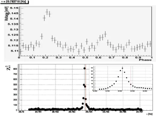
Figure 2. Upper plot: Crab light-curve. Lower plot: Z statistical test. In the box on the left, a zoom of the region around the expected frequency.
3. Crab observations
The whole system has been installed at the end of March ’05 and tested by observing the Crab pulsar. The DC current from the central pixel, converted to voltage, was digitized at a sampling frequency rate of 2 kHz by means of a 16-bits National Instruments PCI-6034E ADC card [10] and stored for off-line analysis. The ADC card was set to a resolution of 0.16 -volts.
A time stamp reflecting this frequency was associated at each event (the absolute event times were not available at that time) and transformed to an inertial reference frame, which is assumed as the solar barycenter system.
For this transformation, the TEMPO software [12] has been used.
As the Crab pulses are completely embedded in noise (generated by the night sky background and the electron- ics), in order to observe its optical pulsation at the expected frequency, the corrected times must be folded with the radio ephemerides corresponding to the observation time provided by the Jodrell Bank observatory [13]. A phaseogram was produced around the expected Crab rotational frequency for each independent test frequency defined by the Independent Fourier Spacing IFS=1/T . The folded intensities were tested against a uniform distribution by performing the Z statistical test. Figure 2 (lower plot) shows the Z test scanning different frequencies around the expected Crab frequency. A clear peak appeared at the frequency expected for the observation epoch. Figure 2 (upper plot) shows the well-known double-peaked lightcurve calculated at the maximum Z value and after 20 min. of observation.
4 F. Lucarelli et al.
4. Conclusions
In this work, we have reported about the installation of the central pixel system of the MAGIC telescope, dedicated to optical observations. The central pixel has been tested successfully by the detection of the Crab optical pulsations. The minimum time requested for a 5 detection was lower than 1 minute. The expected detection time was 30 sec [2]. However, due to extreme weather conditions preceding the weeks immediately before the observations, the optical conditions of the telescope were not the optimal. The pointing error of the telescope was estimated offline in about 0.1
, while the Point Spread Function (PSF) was around 0.1
(FWHM).
This limited the amount of collected light over the Central Pixel to about 7-9% of the total light emitted by the pulsar. Besides that, the observation was done at very high zenith angle, with a strong background due to zodiacal light. Recent alignments of the mirror have reduced the PSF to less than 0.05
. Thus, we expect to improve the detection time by a factor at least 10.
The applications of the central pixel will be focused mainly in the simultaneous observations of the Crab pulsar in the optical and regimes, in order to have real-time ephemerides for periodicity search in -rays. Before that, the central pixel will be also used to test the whole timing system of the MAGIC telescope [11]. Optical observations of flaring AGNs (Mrk 421, 501, ..) and X-ray binary systems (AE Aquarii) are also contemplated.
5. Acknowledgements
The authors wish to thank the financial support given by the CICYT (project FPA2003-9543-C02-01) to make this work and the IAC for providing excellent working conditions in La Palma. The MAGIC telescope is mainly supported by BMBF (Germany), CICYT (Spain), INFN and MURST (Italy).
References
[1] Fonseca, M.V., Acta Physica Polonica B, vol. 30, 2331 (1999).
[2] O˜na-Wilhelmi, E., et al., Astropart. Phys. 22, 95 (2004).
[3] Srinivasan, R., et al., Proc. Towards a Major Atmospheric ˇCerenkov Detector V, Durban (1997) p.51.
[4] De Naurois, M., et al., ApJ 566, 343 (2002).
[5] Franzen, A., et al., Proc. 28th ICRC, Tsukuba (2003).
[6] Ostankov, A., et al., NIM A, vol. 442, Issue 1-3, 117 (2000).
[7] http://www.magic.iac.es/subsystems/centralpixel/
[8] http://content.honeywell.com/sensing/prodinfo/infrared/catalog/0331eng.pdf [9] http://content.honeywell.com/sensing/prodinfo/fiberoptic/application/on7eng.pdf [10] http://sine.ni.com/nips/cds/view/p/lang/en/nid/11916
[11] Lucarelli, F., et al., ”The timing system of the MAGIC telescope”, Proc. of the 19th ECRS, Florence (Italy), 2004 (in preparation) and http://www.magic.iac.es/subsystems/timing.html.
[12] Manchester, R.N., et al., MNRAS 328, 17 (2001).
[13] http://www.jb.man.ac.uk/ pulsar/crab.html