29th International Cosmic Ray Conference Pune (2005)00, 101–106
A tracking monitor for the MAGIC Telescope
B.Riegel
a, T.Bretz
a, D.Dorner
a, R.M.Wagner
bfor the MAGIC Collaboration
c(a) Institut f¨ur Theoretische Physik und Astrophysik, Universit¨at W¨urzburg, Am Hubland, 97074 W¨urzburg, Germany (b) Max-Planck-Institut f¨ur Physik (Werner-Heisenberg-Institut), M¨unchen, Germany
(c) Updated collaborator list at: http://magic.mppmu.mpg.de/collaboration/members/index.html
Presenter: B.Riegel (riegel@astro.uni-wuerzburg.de), ger-riegel-B-abs2-og27-poster
The 17m diameterMAGIC Cherenkov telescope on the Canary island La Palma measures cosmic rays by detecting Cherenkov light from atmospheric air showers. To increase the accuracy of the tracking to the arcsec level a guiding system is used. Since gamma ray sources typically are not visible in the optical, we rely on bright ”guiding stars”, so a starfield guidance is mandatory. As a result we get the positional offset of the telescope, which is determined by comparing the positions of the detected stars with the positions calculated from a star catalog. As an additional feature, the CCD camera of the starguiding system can be used to check the point spread function and to monitor the sky brightness.
1. Introduction
The tracking system of theMAGICtelescope [1], located on the Canary Island La Palma, must meet different demands: During normal operations the 60 ton telescope has to be repositioned accurately and maintain a given position during tracking with high precision, i.e. better than the PSF of theγ-ray signal (∼0.1◦). For GRB follow-up observations it is necessary to reposition the telescope to an arbitrary point in the sky within 20 seconds.
Up to now the 14 bit-shaftencoders measure the angular position of the telescope with an accuracy of about 0.022◦. The star guiding system provides yet higher precision to monitor the performance of the tracking accuracy.
Figure 1. Left: Display window of the tracking monitor. With the three LEDs mounted on the PMT-camera frame a calibration is possible. To visualize the image of the bright star reflected from the main mirror to the PMT-camera a curtain was attached. Right: CCD-camera Watec WAT 902H
2 B.Riegel et al.
In contrast to optical astronomy, gamma-ray sources are typically too dim in the optical to be used for centering and monitoring the source position. Guiding Cherenkov telescopes therefore relies on tracking stars with their well-known sky positions. A low-prize, off-the-shelf video camera (Fig. 1) was attached to the center of the main dish of theMAGICtelescope monitoring LEDs mounted on the PMT-camera frame and stars from the celestial background.
The CCD-camera features a very high sensitivity of 0.0003 lux at the cost of a poor signal to noise ratio. By averaging over 125 frames (five seconds) the high noise level can be reduced and full use of the high sensitivity can be made (Fig. 2).
Figure 2.Comparison of a single frame and a picture integrated over 125 frames (five seconds)
Figure 3. This figure shows the two dimensional distribution of the x- and y-components of the differences between the nominal and the measured star positions. Due to the strong correlation between the CCD-image and the catalog starfield a clear maximum peak is visible providing the mispointing of the telescope
A tracking monitor for theMAGICTelescope 3
2. Tracking Monitor
In the display monitor with 460×460 pixels (6.2◦×6.2◦) typically 40-50 stars are visible (limiting magnitude 8.6) of which the brightest 10 (mag 7.2) are readily recognized.
The difference between nominal (after astrometrical and misalignment corrections) and actual pointing direc- tion of the telescope, the mispointing, is calculated by a comparison between the starfield around the point- ing position and cataloged stars. A two-dimensional histogram (dx/dy) is filled with the differences between the catalog positions of each star and all measured star positions. Because of the randomness of the dx/dy- distribution of the uncorrelated data points a clear maximum can be identified as shown in Fig. 3. The maxi- mum in the histogram characterizes the mispointing of the telescope. By correlating also their magnitudines the algorithm can be improved further. This offset is reported to the run control system for on-site inspection and is read out to the datastream.
To demonstrate the performance of the tracking control system, we show in Fig. 4 the effect of a sudden stop during a regular tracking maneuver, which enforces an artificial mispointing.
Observation Time [s]
0 500 1000 1500 2000 2500 3000 3500 4000 4500 5000
]°Azimuth angle [
-10 -8 -6 -4 -2 0 2 4
] vs Observation Time [s]
Azimuth angle [°
Observation Time [s]
0 500 1000 1500 2000 2500 3000 3500 4000 4500 5000
Azimuth angle [au]∆
-0.4 -0.3 -0.2 -0.1 -0
] vs Observation Time [s]
° Mispointing Azimuth (uncalibrated) [
Figure 4.Upper panel: Azimuth angle during tracking with a short interruption at∼2600 s - 2900 s. Lower panel: Artificial Mispointing enforced by stopping to track
4 B.Riegel et al.
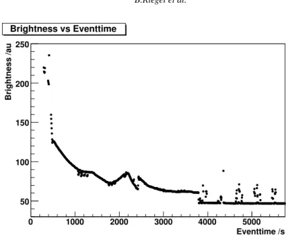
Eventtime /s
0 1000 2000 3000 4000 5000
Brightness /au
50 100 150 200 250
Brightness vs Eventtime
Figure 5.Sky brightness vs observation time. Starting at dawn into the astronomical night. Brightness fluctuations reflects the image of bright stars through the FOV
3. Additional Features
There are diverse possibilities for applications of the tracking monitor of theMAGICtelescope. First it is used to check the accuracy of the position adjustment both on location and afterwards during data analysis. For ex- ample, a problem which became apparent during commissioning, viz. a short mispointing during culmination of the tracked targets, could be solved. Also the sagging of the PMT-camera with increasing zenith angle could be visualized and used to obtain accurate pointing models correcting the effect.
Other interesting features are: (i) Measuring the point spread function of the telescope by attaching a curtain on the PMT-camera (see Fig. 1), and (ii) measuring the sky brightness by analyzing the noise content of the video camera (Fig. 5).
4. Acknowledgments
We acknowledge the support of the German Ministry of Education and Research BMBF (05 CMOMG1/3).
We are also grateful to the Instituto de Astrof´ısica de Canarias (IAC) for the use of the MAGIC site at the Observatorio del Roque de los Muchachos (ORM) and for the excellent working conditions on La Palma.
References
[1] T.Bretz, D.Dorner, R.Wagner: The Tracking System of theMAGICTelescope. In: Proc. 28th ICRC, 2003