COUPLED-BUNCH INSTABILITY SUPPRESSION USING RF PHASE MODULATION AT THE DELTA STORAGE RING
∗M. Sommer†, M. Höner, B. Isbarn, S. Khan, B. Riemann, T. Weis
Center for Synchrotron Radiation (DELTA), TU Dortmund University, Dortmund, Germany
Abstract
In this paper, a feedback-based method to measure the damping rates of multibunch modes at the 1.5-GeV electron storage ring DELTA operated by the TU Dortmund Univer- sity is presented and the influence of an RF modulation on these damping rates is analyzed. For this purpose, the ampli- tude as well as the frequency of the modulation was varied.
The suppression of coupled-bunch instabilities could be ob- served with a modulation frequency slightly below twice and three times the synchrotron frequency. However, the determination of damping rates for high modulation ampli- tudes using the presented method is problematic.
In addition, the decrease of beam quality using RF phase modulation was investigated and the increase of bunch length was measured as a function of the modulation amplitude.
INTRODUCTION
The upcoming upgrade of BESSY II, called BESSY-VSR [1], involves the utilization of superconducting multicell RF-resonators to provide short and long bunches simultane- ously. The residual impedances of the cavities may cause collective multibunch instabilities at the frontier of stability available from current bunch-by-bunch feedback systems.
Hence, other damping methods have to be considered, e.g.
a modulation of the radio frequency (RF) of the accelerat- ing cavity. The effects of RF phase modulation in circular accelerators date back to the early 1990’s [2] [3]. In 2008, a modulation had been applied at the 1.5-GeV electron storage ring DELTA operated by the TU Dortmund University (see Fig. 1 and Table 1) in order to suppress longitudinal insta- bilities [4] [5]. In 2011, a digital bunch-by-bunch feedback system [6] was installed for beam diagnostics purposes [7].
This system is able to suppress the aforementioned instabil- ities succesfully, without the application of the RF phase
U250 (FEL)
BL0
BL1 BL2 BL3 BL4
BL5
BL6
BL7 BL8
BL9BL10 BL11 BL12
U55 SAW
BoDo Gun
Delta Linac
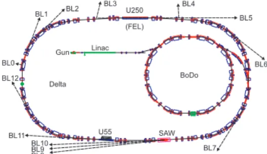
Figure 1: Overview of the DELTA facility including the storage ring and its booster synchrotron BoDo.
∗Work supported by the BMBF under contract no. 05K13PEB
†malte.sommer@tu-dortmund.de
modulation. During user operation, the RF modulation is routinely in operation to increase the beam lifetime by up to 20% due to the reduction of the mean electron density and, thus, the rate of Touschek scattering [8]. To get a deeper understanding of the suppression of instabilities by RF phase modulation, the bunch-by-bunch feedback system is used to determine the damping rates of all coupled-bunch modes.
Experimental Setup
To extract the horizontal, vertical and longitudinal po- sition of every bunch, a combination of a beam position monitor and a hybrid network is used. The horizontal and vertical differential signals as well as the sum signal are sent to the feedback frontend, where they are filtered, attanuated and digitized. By applying a 24-tap FIR filter on consec- utive input data, the output signals are created, which are converted to analog signals driving the power amplifiers and the corresponding kicker structures. In addition, the pro- cessing units include a frequency generator, which allows to send a dedicated RF signal to the beam, for example to excite a specific multibunch mode [9].
The modulation of the RF phase of the accelerating cavity is realized by an external system. It mainly consists of elec- trical phase shifters and a signal generator with variable fre- quency and amplitude (for detailed information see [5]).The signal modulation of the DELTA RF master generator is given by
URF(ω)=U0sin(ωRFt+a·sin(ωmodt))
with the amplitudeU0, the RF frequencyωRF, the modula- tion amplitudeaand the modulation frequencyωmod. At the signal generator, the modulation frequency fmod =ωmod/2π can be set directly and the modulation amplitudeacan be set via input signalUmodfrom 0 V up to 3 V. The standard set- tings for user operation areUmod=0.7 V andωmod ≈2·ωs, with the synchrotron frequency fs=ωs/2π.
Table 1: Storage Ring Parameters
parameter value
revolution frequency 2.6 MHz
RF frequency 500 MHz
nominal RF power loss 26 kW
maximum beam current (multibunch) 130 mA maximum beam current (single bunch) 20 mA synchrotron frequency 15.2 - 16.4 kHz fractional horizontal tune 0.10 - 0.20
fractional vertical tune 0.20 - 0.30
6th International Particle Accelerator Conference IPAC2015, Richmond, VA, USA JACoW Publishing
ISBN:978-3-95450-168-7 doi:10.18429/JACoW-IPAC2015-MOPWA034
5: Beam Dynamics and EM Fields
D01 - Beam Optics - Lattices, Correction Schemes, Transport
MOPWA034 179
ContentfromthisworkmaybeusedunderthetermsoftheCCBY3.0licence(©2015).Anydistributionofthisworkmustmaintainattributiontotheauthor(s),titleofthework,publisher,andDOI.
DAMPING TIMES OF COUPLED-BUNCH MODES
In a first step, a method was developed to measure the damping rates of allh=192 multibunch modes at DELTA.
Below the instability threshold, a specific coupled-bunch mode is excited by the frequency generator of the bunch-by- bunch feedback system while the longitudinal bunch posi- tions are recorded. In between, the excitation is switched off for a few milliseconds and the oscillation is damped. This measurement, called grow-damp measurement, is repeated for every multibunch mode while the damping rates are ob- tained by exponential fits. In Fig. 2, a measurement for mode no. 20 is shown in time domain (a), frequency domain (b) and with an exponential fit to obtain the damping rate (c).
The resulting damping rates of all 192 modes are shown in (d). As expected from analytical calculations, the pairs of modes µand h−µshow an anti-correlated behaviour.
While one mode damps slower, the other has a higher damp- ing rate than the zero-current value. For further information see [7] [9] [10].
Figure 2: Bunch oscillation amplitudes in time domain (a) and mode amplitudes in frequency domain (b). The ex- citation is switched off for several milliseconds while the damping rate is obtained by an exponential fit (c). Observed damping rates for all longitudinal modes (d) are plotted in red (modes 0-95) and blue (modes 96-191).
COUPLED-BUNCH INSTABILITY SUPPRESSION BY RF MODULATION
In order to analyze the influence of the RF phase mod- ulation on the damping rates of all multibunch modes, the method shown in the previous section is used. Since the RF phase is modulated in the kHz regime, the accelerating
gradient varies in the same regime as the synchrotron fre- quency. Therefore, the longitudinal accelerating gradient of every electron changes, which leads to slightly different syn- chrotron frequencies for every single particle. This results in an incoherent motion of the electrons in every bunch. In con- sequence, the coherent excitation of coupled-bunch modes is suppressed. This takes effect for every longitudinal mode and is observable also for horizontal modes due to dispersion.
As seen in Fig. 2, the most unstable longitudinal mode (with the lowest damping rate) at DELTA is mode 12. In Fig. 3, this mode is under investigation while the generator voltage was varied from 0 V to 1.3 V in 0.05 V steps (see Fig. 3).
The frequency generator of the bunch-by-bunch feedback system was used at a frequency of f12=31216 kHz on all bunches to excite the longitudinal mode 12. The excitation started at 7 ms and was switched off 3 ms later. With a beam current of 34.5 mA at the beginning of the measurement, the beam was far below the instability threshold and, therefore, damped. The total acquisition time amounted to 50 ms. This process was repeated for variable amplitudes of the modula- tion at a frequency of fmod≈2· fs =31.8 kHz. During the whole measurement, the beam current decreased by less than 0.05 mA and its deviation was, therefore, negligible. While determining the damping rates via exponential fit worked fine for small modulation amplitudes, the shape of the mea- sured curve changed for modulation amplitudes higher than 0.5 V. Above this value, exponential fits are no longer ac- curate for the description of the measured data. While this effect gets even worse for higher modulation amplitudes up to the maximum of 3 V, the maximum oscillation ampli- tudes decrease. This shows, that the excitation of mode 12 is suppressed depending on the amplitude of the RF phase modulation. However, to determine the damping rates of coupled-bunch modes under the influence of an RF phase modulation, the used method is not applicable and a new analysis method is necessary.
0.10 0.30.2 0.50.4 0.70.6 0.90.8 1.11.0 1.31.2 0
10 20
30 40
50 0
1 2 3 4
Umod/ V modulation frequency: 31.80 kHz
time / ms
mode amplitude / a.u.
Umod/ V 0 0.1 0.2 0.3 0.4 0.5 0.6 0.7 0.8 0.9 1 1.1 1.2 1.3
Figure 3: Grow-damp measurements for different amplitudes of the RF phase modulation with a modulation frequency of fmod ≈ 2· fs = 31.8 kHz. Exponential fits to deter- mine the damping rate are not viable for amplitudes above Umod=0.5 V.
6th International Particle Accelerator Conference IPAC2015, Richmond, VA, USA JACoW Publishing
ISBN:978-3-95450-168-7 doi:10.18429/JACoW-IPAC2015-MOPWA034
MOPWA034 180
ContentfromthisworkmaybeusedunderthetermsoftheCCBY3.0licence(©2015).Anydistributionofthisworkmustmaintainattributiontotheauthor(s),titleofthework,publisher,andDOI.
5: Beam Dynamics and EM Fields D01 - Beam Optics - Lattices, Correction Schemes, Transport
Frequency Dependence
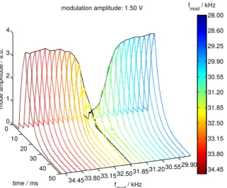
The modulation frequency fmodis another important pa- rameter for the influence of the RF phase modulation on the instability suppression. The influence is investigated by the same grow-damp measurements as used before with a fixed generator voltageUmod=1.5 V. As can be seen in Fig. 4, the modulation frequency has to be set slightly below twice the synchrotron frequency. With fs = 16.05 kHz, the maximum suppression of the longitudinal mode 12 is reached with a modulation frequency of fmod =31.8 kHz.
A deviation of the modulation frequency of±1.5 kHz from the optimal value extinguishes the suppression effect.
29.90 30.55 31.20 31.85 32.50 33.15 33.80 34.45 0
10 20
30 40
50 0
1 2 3 4
fmod/ kHz modulation amplitude: 1.50 V
time / ms
mode amplitude / a.u.
fmod/ kHz 28.00 28.60 29.25 29.90 30.55 31.20 31.85 32.50 33.15 33.80 34.45
Figure 4: Grow-damp measurements for variable mod- ulation frequencies fmod with the synchrotron frequency fs=16.05 kHz. The suppression of multibunch mode 12 is maximized for fmod=31.8 kHz (black curve).
Another method to analyze the frequency dependence of instability suppression is obtaining the spectral power at the mean synchrotron frequency of all bunches. For this pur- pose, grow-damp measurements were repeated for variable modulation frequencies from 28 kHz to 54 kHz. As can be seen in Fig. 5, previous results are confirmed, since the maximum instability suppression is obtained at fmod=31.8 kHz. In addition, instability suppression could also be de- tected at fmod≈3· fs=47.7 kHz, as expected from pre- vious works [3]. Here, a deviation of±0.5 kHz already extinguishes the suppression effect.
Beam Quality Decrease
Next to the suppression of coupled-bunch instabilities and the increase of beam lifetime, the modulation of the RF phase also has a negative influence on the beam quality. Due to the excitation of incoherent motion inside the bunches, the bunch length increases depending on the modulation amplitude. To investigate this phenomenon, a streak camera was used for the determination of the bunch length while the generator voltage was varied from 0 V to 3 V. The results show that in normal user operation, withUmod =0.7 V, the bunch length increase is less than 20%. With a modulation
amplitude of 1 V, the bunches get prolonged by approx. 35%.
With 2 V, the effect increases to circa 85% and with the maximum modulation amplitude of 3 V, the bunch length increases by about 120%. In addition, the longitudinal phase space changes. For high modulation amplitudes, the number of stable islands in the phase space increases, which leads to sub-bunches revolving around the center of mass. For detailed information see [3] [5] [11] [12].
Figure 5: Spectral power at the synchrotron frequency fs= 16.05 kHz of all bunches for variable modulation frequen- cies. Coupled-bunch instability suppression is maximized for fmod =31.6 kHz and also achievable for fmod =47.8 kHz.
CONCLUSION AND OUTLOOK
With a new measurement method where every multibunch mode is preexcited by the frequency generator of the bunch- by-bunch feedback system, it is possible to determine the damping rate of every mode in a circular accelerator. Sup- pressing coupled-bunch modes with an RF phase modula- tion can be detected by decreasing maximum amplitudes in grow-damp measurements depending on the modulation amplitude. However, determination of damping rates by exponential fit is problematic. Using a frequency dependent measurement, it can be shown that the modulation frequency has to be set slightly below a multiple of the synchrotron frequency. However, streak camera measurements demon- strates that the bunch length increases the higher the modula- tion amplitude is set. The use of an RF modulation could be an option for the BESSY-VSR project to add more stability at the cost of a slightly reduced brilliance and a bunch length increase.
ACKNOWLEDGEMENT
It is a pleasure to thank all our colleagues at DELTA and the BMBF for the continuous support. The project has also profited from the expertise of D. Teytelman (Dimtel Inc.).
6th International Particle Accelerator Conference IPAC2015, Richmond, VA, USA JACoW Publishing
ISBN:978-3-95450-168-7 doi:10.18429/JACoW-IPAC2015-MOPWA034
5: Beam Dynamics and EM Fields
D01 - Beam Optics - Lattices, Correction Schemes, Transport
MOPWA034 181
ContentfromthisworkmaybeusedunderthetermsoftheCCBY3.0licence(©2015).Anydistributionofthisworkmustmaintainattributiontotheauthor(s),titleofthework,publisher,andDOI.
REFERENCES
[1] G. Wüstefeld et al., “Simultaneous Long and Short Electron Bunches in the BESSY II Storage Ring”, Proc. of IPAC’11, San Sebastián, THPC014.
[2] H. Huang et al., “Experimental determination of the Hamil- tonian for synchrotron motion with RF phase modulation”, Phys. Rev. E48, 4678, 1993.
[3] N.P. Abreu et al., “Longitudinal dynamics with RF phase modulation in the Brazilian electron storage ring”, Phys. Rev.
ST Accel. Beams 9, 124401, 2006.
[4] S.Khan, J.Fürsch, P. Hartmann, T. Weis, D. Teytelman, “Stud- ies and Control of Coupled-Bunch Instabilities at DELTA”, Proc. of IPAC’10, Kyoto, Japan, WEPEB032.
[5] J. Fürsch, “Lebensdauerverbesserung und Strahlstabilisie- rung durch longitudinale Phasenmodulation am Elektronen- speicherring Delta”, Dissertation, TU Dortmund University, 2014.
[6] Dimtel Inc.http://www.dimtel.com
[7] M. Höner, “Investigation of Transient Processes at the DELTA Electron Storage Ring Using a Digital Bunch-by-Bunch Feed- back System”, Dissertation in preparation, TU Dortmund University, 2015.
[8] S. Sakanaka et al., “Improvement in the Beam Lifetime by Means of an RF Phase Modulation at the KEK Photon Factory Storage Ring”, Phys. Rev. ST Accel. Beams 3, 050701, 2000.
[9] M. Höner et al., “Bunch-by-Bunch Feedback Systems at the DELTA Storage Ring Used for Beam Diagnostics”, Proc. of IBIC’14, Monterey, California, USA, WEPD26.
[10] A. Chao, “Physics of Collective Beam Instabilities in High Energy Accelerators”, New York, NY: Wiley & Sons, 1993.
[11] J. M. Byrd, W.-H. Cheng, F. Zimmermann, “Nonlinear Ef- fects of Phase Modulation in an Electron Storage Ring”, Phys.
Rev. E57, 4706, 1998.
[12] F. Orsini and A. Mosnier, “Effectiveness of RF Phase Modula- tion for Increasing Bunch Length in Electron Storage Rings”, Phys. Rev. E 61, 4431, 2000.
6th International Particle Accelerator Conference IPAC2015, Richmond, VA, USA JACoW Publishing
ISBN:978-3-95450-168-7 doi:10.18429/JACoW-IPAC2015-MOPWA034
MOPWA034 182
ContentfromthisworkmaybeusedunderthetermsoftheCCBY3.0licence(©2015).Anydistributionofthisworkmustmaintainattributiontotheauthor(s),titleofthework,publisher,andDOI.
5: Beam Dynamics and EM Fields D01 - Beam Optics - Lattices, Correction Schemes, Transport