BUNCH-BY-BUNCH FEEDBACK SYSTEMS AT THE DELTA STORAGE RING ∗
M. H¨oner † , A. Nowaczyk,
M. Bakr, H. Huck, S. Khan, R. Molo, A. Schick, P. Ungelenk, M. Zeinalzadeh
Center for Synchrotron Radiation (DELTA), TU Dortmund University, 44227 Dortmund, Germany Abstract
At the DELTA 1.5-GeV electron storage ring operated as a synchrotron radiation source by the TU Dortmund Uni- versity, bunch-by-bunch feedback systems have been re- cently installed and commissioned to detect and suppress longitudinal as well as transverse multibunch instabilities.
Besides that, the feedback systems are used as a diagnos- tics tool. Growth rates of multibunch instabilities and their dependence on the beam current have been measured. Ad- ditionally, the oscillation amplitudes of electron bunches have been studied during the injection process.
INTRODUCTION
Figure 1: Overview of the DELTA facility.
At the 1.5-GeV synchrotron radiation source DELTA op- erated by the TU Dortmund University, multibunch insta- bilities occur at a current threshold around 70 mA. The typical fill pattern comprises ≈140 bunches in 192 RF buckets. To investigate and suppress multibunch instabil- ities, bunch-by-bunch feedback systems and the respec- tive kicker structures were installed in 2011 in the north- ern part of the storage ring (Fig. 1). So far, the feedback systems are in use during coherent harmonic generation (CHG) experiments [1, 2] to improve the laser-electron interaction and to perform beam studies in dedicated ma- chine shifts. In standard user shifts, an RF phase mod- ulation increases the beam lifetime precluding the use of the feedback system. To detect the longitudinal and trans- verse position of electron bunches, a beam position moni- tor (BPM) is used. A hybrid network provides the differ- ential signals ∆x and ∆y as well as the sum signals for the feedback frontend [3], in which the analog signals pass
∗
Work supported by BMBF (05K10PEB)
†
markus.hoener@tu-dortmund.de
a two-cycle comb filter and are mixed with a multiple of the RF frequency. Remote-controllable phase shifters and attenuators allow to set the phase-sensitive (longitudinal) and amplitude-sensitive (transverse) detection mode. After passing a low-pass filter, the analog signals are digitized us- ing 12-bit analog-digital converters. Each processing unit uses a 32-tap FIR (finite impulse response) filter to com- pute a correction signal which is converted to an analog sig- nal and sent to a power amplifier driving the kicker struc- ture (Fig. 2). Both transverse feedback systems employ a common stripline kicker [4]. For each axis, only one elec- trode is connected and the opposite electrode is kept float- ing. For the longitudinal case, a strongly damped kicker cavity is used, employed to obtain the necessary bandwidth of 250 MHz [4].
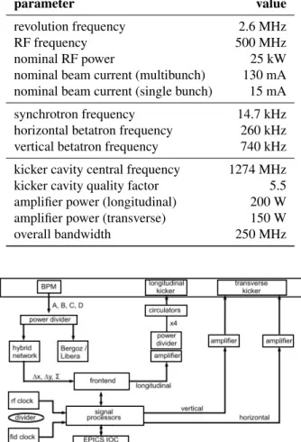
Table 1: specific parameters
parameter value
revolution frequency 2.6 MHz
RF frequency 500 MHz
nominal RF power 25 kW
nominal beam current (multibunch) 130 mA nominal beam current (single bunch) 15 mA
synchrotron frequency 14.7 kHz
horizontal betatron frequency 260 kHz vertical betatron frequency 740 kHz kicker cavity central frequency 1274 MHz kicker cavity quality factor 5.5 amplifier power (longitudinal) 200 W amplifier power (transverse) 150 W
overall bandwidth 250 MHz
BPM
hybrid network
frontend
signal processors
longitudinal
kicker transverse
kicker
Bergoz / Libera A, B, C, D
power divider amplifier circulators
amplifier amplifier
rf clock
fid clock divider
EPICS IOC power divider
∆x, ∆y, Σ
x4
longitudinal
horizontal vertical
Figure 2: Overview of the feedback systems.
Proceedings of IPAC2012, New Orleans, Louisiana, USA MOPPR015
06 Instrumentation, Controls, Feedback and Operational Aspects T03 Beam Diagnostics and Instrumentation
ISBN 978-3-95450-115-1
807 Copyright c ○ 2012 by IEEE – cc Cr eati v e Commons Attrib ution 3.0 (CC BY 3.0) — cc Cr eati v e Commons Attrib ution 3.0 (CC BY 3.0)
ABSOLUTE CALIBRATION Longitudinal Feedback System
The calibration of the longitudinal feedback unit was performed in the linear region of the phase-sensitive de- tection mode (inset of Fig. 3). When the RF power is re- duced, the synchronous phase φ
schanges. To calibrate the phase detector signal (∼ I∆φ
s), the position of the elec- tron bunches in terms of the RF phase was determined us- ing a laser-induced THz signal. Here, a short laser pulse interacts with a slice of an electron bunch, which gives rise to coherent THz radiation proportional to the number of electrons squared in the interaction area. By changing the delay of the incoupled laser pulse, the longitudinal position of the bunch centroid was determined [5]. Fig. 3 displays the feedback signal to be calibrated under variation of the synchronous phase (in time units). The negative slope of the linear fit is due to the chosen reference phase as shown in the inset of Fig. 3.
-5 0 5 10 15 20 25 30 35 40 45 -100
-200 -300
-400
delay [ps]
A DC -cou nts/ cu rr en t [ 1/ m A ]
-150 -250 -350 -50
Φ
A
Figure 3: Correlation between the feedback signal and the longitudinal position of the electron bunches. The error bars indicate the standard deviation of the ADC counts ac- quired over 25 ms. The inset shows the phase-sensitive region of the reference phase.
Transverse Feedback Systems
To calibrate the transverse feedback units, the electron orbit was shifted at the position of the BPM used by the feedback systems. In the amplitude-sensitive detection mode, the transverse signal recorded by the feedback sys- tem is proportional to I · y with the bunch current I and the oscillation amplitude y. This was compared to the ab- solute position, determined using Bergoz readout electron- ics additionally connected to the BPM. Figure 4 shows the resulting correlation between the feedback signal and the BPM data for the horizontal and vertical plane.
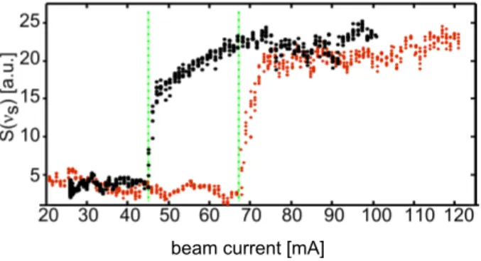
MULTIBUNCH INSTABILITIES Instability Thresholds
At the DELTA storage ring, multibunch instabilities are observed at a beam current above typically 70 mA when the superconducting 5.3-T wiggler is in operation. Switching the wiggler off lowers the instability threshold to about 45 mA due to reduced radiation damping (Fig. 5).
Φ A
0 1 2 3 4 5 6 7 8 200
150 100 50 0 -50 -100 -150 -200
500 400 300 100 0 -100 200
-200 -6 -4 -2 0 2 4 6 hor. displacement [mm] ver. displacement [mm]
a) b)
A DC -cou nts/ cu rr en t [ 1/ m A ]
Figure 4: Absolute calibration of the horizontal (a) and ver- tical (b) feedback system. The inset shows the amplitude- sensitive region of the reference phase.
20 30 40 50 60 70 80 90 100 110 120 25
20 15 10 5 S( ν s) [a.u.]
beam current [mA]
Figure 5: Spectral component at the synchrotron frequency taken from the single-bunch spectrum for different beam currents with the superconducting wiggler switched on (red) and off (black).
Grow-Damp Measurements
In order to investigate the growth rates of longitudinal multibunch instabilities and to determine which modes are excited at DELTA, grow-damp measurements were per- formed. Figure 6a displays a grow-damp measurement taken at a beam current above the instability threshold. The feedback system damps the instabilities until it is disabled at time t = 5 ms. After additional 5 ms, the feedback system is re-enabled. Fig. 6b shows the calculated mode spectrum dominated by the longitudinal multibunch mode 12.
0 10 20
10050 150 0 50 100
Time (ms) a) Osc. Envelopes in Time Domain
Bunch No.
deg@RF
0 10 20
0 100 0 50
Time (ms) b) Evolution of Modes
Mode No.
deg@RF