PLANS FOR AN EEHG-BASED SHORT-PULSE FACILITY AT THE DELTA STORAGE RING
∗S. Hilbrich
†, F.H. Bahnsen, M. Bolsinger, M. Jebramcik, S. Khan, C. Mai, A. Meyer auf der Heide, R. Molo, H. Rast, G. Shayeganrad, P. Ungelenk,
Center for Synchrotron Radiation (DELTA), TU Dortmund University, 44227 Dortmund, Germany Abstract
The 1.5-GeV synchrotron light source DELTA, operated by the TU Dortmund University, includes a short-pulse facil- ity based on the coherent harmonic generation (CHG) tech- nique, which allows for the generation of radiation pulses with wavelengths down to 53 nm and durations of 50 fs. In order to reach even shorter wavelengths, the present setup will be modified to employ the echo-enabled harmonic gen- eration (EEHG) and femtoslicing techniques.
INTRODUCTION
At DELTA, a 1.5-GeV synchrotron light source operated by the TU Dortmund University (see Fig. 1), ultrashort co- herent synchrotron radiation pulses are provided by a short- pulse facility [1] based on coherent harmonic generation (CHG) [2]. The goal is to generate radiation at wavelengths down to 53 nm with a pulse duration of 50 fs. In order to access even shorter wavelengths, the present facility will be modified [3] to employ the echo-enabled harmonic genera- tion (EEHG) technique [4] and the femtoslicing scheme [5]
as additional radiation sources.
Coherent Harmonic Generation
As part of the CHG technique [2], the electron energy is modulated sinusoidally by a co-propagating laser pulse in an undulator (modulator). The laser pulse is typically 1000 times shorter than the electron bunch in the storage ring.
Downstream of the modulator, the electrons pass a magnetic chicane resulting in a microbunching which gives rise to co-
Figure 1: Sketch of the synchrotron light source DELTA. The yellow frame marks the CHG facility in the northern part of the storage ring. Synchrotron radiation is provided by dipole magnets, the undulators U55, U250 and the superconducting asymmetric wiggler (SAW).
∗Work supported by DFG, BMBF, FZ Jülich and by the Federal State NRW.
†svenja.hilbrich@tu-dortmund.de
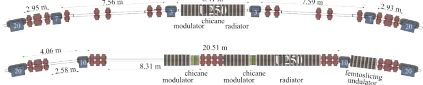
Figure 2: Top: Schematic view of the EEHG and CHG setup.
Center: The electron distribution in longitudinal phase space (relative energy deviation∆E/Eversus longitudinal coordi- nate zin units of the laser wavelengthλ) before and after the first and second chicane. Bottom: Electron density dis- tribution after the second chicane in the case of EEHG.
herent radiation at the laser wavelength or harmonics thereof in a second undulator (radiator). The bunching factor char- acterizes the correlation between the longitudinal positions of the electrons with respect to the laser wavelengthλand is defined as [6]
bn= 1 N
XN
k=1
e−2πi zkn/λ
, (1)
wherenis the harmonic number,Nis the number of electrons andzis the longitudinal position of an electron. The power of the CHG radiation scales as Pn(λ) ∼ N2b2n(λ) with bn(λ) ∼e−n2 [7, 8]. This short-pulse technique can only be employed if the intensity of the short coherent pulse is higher than that of the long incoherent background (∼N).
This is the case for harmonics up ton≈5.
Echo-Enabled Harmonic Generation
The EEHG scheme [4], which was originally proposed for FEL seeding, requires one more modulator and chicane compared to the CHG setup. In the first modulator, the elec- tron energy is modulated sinusoidally with the periodicity of the laser wavelength. In the first chicane, the electron distribution is strongly sheared in the longitudinal phase space (see Fig. 2). In the second modulator, the electron en- ergy is modulated again with a second laser pulse and in the following chicane, a density modulation with high harmonic content is generated. For EEHG, the bunching factor scales asbn(λ)∼n−1/3, if the energy modulation amplitude and chicane strength are optimized for each harmonic [9].
©2015CC-BY-3.0andbytherespectiveauthors
Figure 3: Top: Present magnetic setup in the northern part of DELTA. Bottom: Planned magnetic setup for the implementa- tion of EEHG and femtoslicing in which the 3- and 7-degree dipole magnets are replaced by two 10-degree dipole magnets (adapted from [10]).
Femtoslicing
In contrast to the CHG and EEHG schemes, the fem- toslicing technique [5] is based on a spatial separation of energy-modulated electrons downstream of the modulator by a dispersive element, e. g., a dipole magnet. In a follow- ing radiator, the off-energy electrons radiate incoherently at the radiator wavelength. In contrast to CHG and EEHG, the radiator can be tuned to arbitrary wavelengths and po- larization. However, the intensity of incoherent radiation from a small fraction of the electrons in the bunch is very low. In the future DELTA short-pulse facility, EEHG and femtoslicing radiation initiated by the same laser pulse will be used simultaneously.
Modification of the Present Short-Pulse Facility
The present short-pulse facility at DELTA [1] is located in the northern part of the storage ring. A 17-period elec- tromagnetic undulator (U250) serves as modulator, chicane and radiator. In order to implement the EEHG technique, two additional 7-period electromagnetic undulators were procured and are already in house. They will be employed as modulators, whereas the undulator U250 will be used as radiator only.
For a successful implementation of EEHG, both modula- tors, the chicanes, and the radiator should be placed in one long straight section because dipole magnets would smear out the microbunches. Furthermore, the distance between the second modulator and the radiator has to be minimized because the angular spread of the electrons results in differ- ent path lengths along a drift space. In order to create the required straight section, the storage ring has to be modified without changing its circumference significantly [10]. The resulting new magnetic layout of the short-pulse facility is shown in Fig. 3 and Table 1 summarizes the properties of the present and future storage ring lattice.
LATTICE OF THE FUTURE SHORT-PULSE FACILITY
The model of the new short-pulse facility proposed in [10] and [11] is based on a storage ring lattice showing discrepancies to the actual layout of the storage ring, e. g., the circumference differs by 3.8 cm between the model and the length calculated from the RF frequency of the accelerating
Table 1: Lattice Properties of the Present and Future DELTA Storage Ring
Parameter Present EEHG
circumference 115.164 m 115.176 m bunch length (FWHM) 100 ps 100 ps horizontal emittance 17.5 nm rad 16.5 nm rad
horizontal tune 9.23 9.13
vertical tune 3.33 3.95
cavity. In 2014, the positions of the storage ring magnets were surveyed and based on this data, an improved model with a circumference constistent with the RF frequency was obtained [12]. In this model, asymmetries in the optics due to a misalignment of the magnets were detected which will be reduced by realigning the whole storage ring.
In addition, the model of the future short-pulse facility was adapted to fit the survey results [12]. Figure 4 shows the optical functions of the future short-pulse facility, where the beta functions and dispersion are reduced compared to the present lattice.
SIMULATION OF MICROBUNCHING
In order to study the obtainable bunching factor, a modi- fied version of the codeelegant[13] including a laser beam quality factor M2 larger than unity [14] was used. As an example, the bunching factor for the 40th harmonic of the laser wavelength 800 nm was optimized. In the simulation, a laser pulse energy of 4 mJ, a pulse length of 60 fs and a beam quality factorM2of 1.1 were assumed, resulting in optimumR56values of the magnetic chicanes of 1.25 mm and 24 µm. The waist radiusw0(two standard deviations of intensity) for optimum energy modulation is 0.5 mm in both modulators [10], while the restriction that the energy modulation may not exceed the energy acceptance of the stor- age ring, leads to laser waist radii of 2.68 mm and 1.71 mm.
These parameters yield a maximum energy modulation of 0.33% and 0.49%. The resulting bunching factor optimized for the 40th harmonic of the 800 nm laser radiation is shown in Fig. 5. The achievable value is sufficient to exceed the background of incoherent radiation [11].
©2015CC-BY-3.0andbytherespectiveauthors
Figure 4: Calculated optical functions of the future short- pulse facility [12].
FEMTOSLICING RADIATION
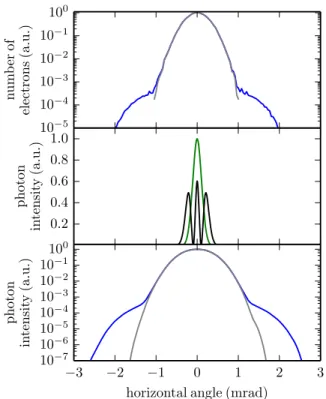
For the following calculations of the femtoslicing radia- tion, a radiator with a period length of 56 mm and 30 pe- riods was considered. Using the modified version of the codeelegant, the energy-modulated electron distribution at the femtoslicing undulator was simulated by tracking the electrons from the first modulator to the femtoslicing undula- tor. Figure 6 shows the angular distributions of the electrons with and without laser-induced energy modulation. As an example, a laser pulse energy of 8 mJ, a waist radiusw0of 1.28 mm, a pulse length of 60 fs (FWHM) and a beam quality factor ofM2=1.1 were assumed. The resulting maximum energy modulation amplitude is 0.90 % corresponding to the energy acceptance of the RF cavity [11].
The angular distribution of the femtoslicing radiation gener- ated by a single electron at a photon energy of 237 eV and at the third harmonic at 711 eV was simulated using the code Spectra[15] (see Fig. 6) [11].
A convolution of both angular distributions was used to calculate the angular distribution of the radiation generated in the femtoslicing undulator at a photon energy of 711 eV (Fig. 6). The short-pulse component exceeds the background radiation for observation angles above 1.5 mrad [11].
MODIFICATION OF THE VACUUM SYSTEM
The new magnetic layout requires a modification of the present vacuum system including chambers and pumps. In order to reduce the cost, as many of the existing chamber parts as possible will be reused in the new setup. Since the 10-degree dipole magnets have a different bending radius than the 3- and 7-degree magnets (see Fig. 3), new dipole chambers have to be manufactured. In addition, tapers and a new design of the vacuum chambers are needed, due to a reduced gap height of the new modulators.
Since both chicanes in the EEHG section displace the electron beam only by a few millimeters [10], no mirrors can be placed at the chicane bumps without decreasing the electron beam lifetime. As a consequence, the laser radiation for the second modulator has to be coupled in at the first
10 20 30 40 50 60
harmonicn 0.00
0.01 0.02 0.03 0.04 0.05 0.06 0.07 0.08 0.09
bunchingfactorbn
Figure 5: Calculated bunching factor versus harmonic n of the 800 nm laser radiation. The bunching factor was optimized for the 40th harmonic [11].
10−5 10−4 10−3 10−2 10−1 100
numberof electrons(a.u.)
0.2 0.4 0.6 0.8 1.0
photon intensity(a.u.)
−3 −2 −1 0 1 2 3
horizontal angle (mrad) 10−7
10−6 10−5 10−4 10−3 10−2 10−1 100
photon intensity(a.u.)
Figure 6: Top: Angular distribution of the electrons at the beginning of the femtoslicing undulator with (blue) and with- out (grey) energy modulation. Center: Angular distribution of the radiation generated by a single electron in the fem- toslicing undulator at a photon energy 237 eV (green) and at the third harmonic (black). Bottom: Angular distribution of the femtoslicing radiation at a photon energy of 711 eV with (blue) and without (grey) the energy modulation [11].
10-degree dipole magnet chamber. In view of the additional impedance, the tube diameter should be as small as possible.
In contrast to this, the laser radiation requires an aperture larger than 4.6 times the beam sizew(z)=w0
q1+(z/zR)2, wherezis the longitudinal coordinate andzRis the Rayleigh length, to avoid diffraction effects which may impair the laser beam quality [16].
©2015CC-BY-3.0andbytherespectiveauthors
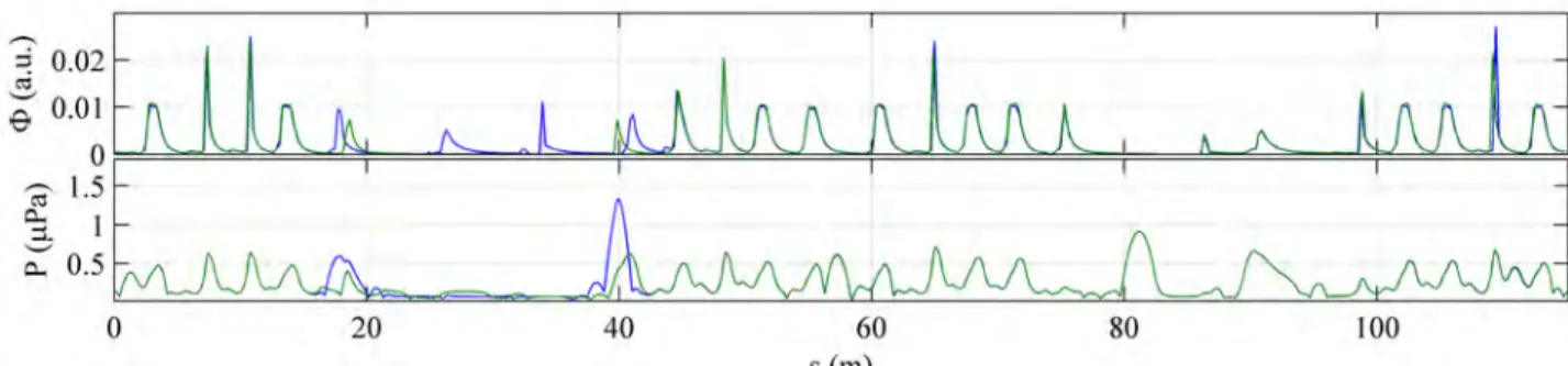
Figure 8: Simulated dipole radiation photon fluxΦon the outer wall of the vacuum chamber (top) at a beam current of 130 mA and pressureP(bottom) versus the longitudinal postionsin the storage ring for the present setup (blue) and for the storage ring modified in the region betweens=14 m and 43 m (green).
In order to generate two laser pulses from one pulse pro- vided by the existing laser system, a beamsplitter for 800-nm or a second harmonic generation (SHG) unit producing 400- nm radiation could be used. Using a laser waist radius of 500 µm for an optimum energy modulation in both modula- tors, the 4.6wradiation envelope along the vacuum chamber was calculated for different beam quality factorsM2. This calculation was performed for 800-nm as well as 400-nm radiation for both laser beams. As shown in Fig. 7, the 800- nm beam is incompatible with a waist size of 500 µm and a diameter of the incoupling tube of 31 mm, which is the diam- eter of already existing beamline tubes. Therefore, a setup for the laser-electron interaction using 800-nm in the first modulator and 400-nm radiation in the second modulator will be adopted.
Simulation of a 1-d Pressure Profile
In order to determine pump positions and types in the modified part of the storage ring, a one-dimensional pres- sure profile was calculated. As a first step, the distribution of the photon flux along the vacuum chamber wall from the bending magnets was determined (see Fig. 8). The radiation caused by the insertion devices was neglected in this model.
The thermal and synchrotron-radiation-induced desorption rates were adjusted such that a lifetime of around 10 hours at 130 mA and 18 hours at 15 mA for the present setup of DELTA was achieved by numerical calculation [17] includ- ing residual gas scattering as well as the Touschek effect.
The pressure simulation was carried out for a pure nitrogen (N2) gas load. For a more refined simulation, the measured gas composition [18] will be included in the model.
The new vacuum system is supposed to keep the average pressure at the present level in order to maintain a similar beam lifetime. Pressure profiles for the present and one possible EEHG pump configuration are shown in Fig. 8.
CONCLUSION
Based on the spatial survey of the storage ring, an im- proved model for the future short-pulse facility was devel- oped, and the simulation of the EEHG microbunching and
Figure 7: Laser radiation diameter (4.6w) of the 800-nm (red) and 400-nm (blue) radiation versus distance to the exit of the laser beam pipe. The aperture (black) is determined by the beamline and by the storage ring chamber dimensions.
The beam quality factorM2varies between 1.0 and 1.3 for 800-nm and between 1.3 and 2.0 for 400-nm laser radiation in steps of 0.05 while keeping the laser waist radius constant atw0 =500µm.
of the femtoslicing radiation show that both techniques can be applied at DELTA.
Resulting from the calculations of the radiation envelope in the vacuum chamber, a setup for a laser-electron interac- tion using two different wavelengths for the two laser pulses will be investigated. Indicated by the calculated pressure profile, the relative change of the pressure due to modifica- tions of pump positions and types is predictable. Including measured gas compositions, a more precise simulation will be possible.
ACKNOWLEDGMENT
It is a pleasure to thank our colleagues at DELTA and the faculty of Physics of the TU Dortmund University for their support. This work was supported by BMBF (05K13PE3), by the DFG (INST 212/236-1 FUGG), by the Helmholtz ARD Initiative, by the FZ Jülich and by the Federal State NRW.
©2015CC-BY-3.0andbytherespectiveauthors
REFERENCES
[1] S. Khan et al., "Generation of Ultrashort and Coherent Syn- chrotron Radiation Pulses at DELTA",Sync. Rad. News26, pp. 25-29, 2013.
[2] R. Prazeres et al., "Coherent harmonic generation in the vac- uum ultraviolet spectral range on the storage ring ACO",Nucl.
Instr. and Meth. A272, pp. 68-72, 1988.
[3] R. Molo et al., "EEHG and Femtoslicing at DELTA", inProc.
35th Int. Free-Electron Laser Conf., New York, 2013, pp.
594-597.
[4] G. Stupakov, "Using the Beam-Echo Effect for Generation of Short-Wavelength Radiation",Phys. Rev. Lett.102, pp.
074801 ff., 2009.
[5] A.A. Zholents, M.S. Zolotorev, "Femtosecond X-Ray Pulses of Synchrotron Radiation",Phys. Rev. Lett.76, pp. 912-915, 1996.
[6] P. Schmüser et al.,Ultraviolet and Soft X-Ray Free-Electron Lasers, Springer, 2008.
[7] L.H. Yu, "Generation of intense uv radiation by subharmoni- cally seeded single-pass free-electron lasers",Phys. Rev. A 44, pp. 5178-5193, 1991.
[8] J. Wu, L. Yu, "X-ray Production by Cascading Stages of a High-Gain Harmonic Generation Free-Electron Laser I:
Basic Theory",SLAC-PUB-10494, 2004.
[9] D. Xiang, G. Stupakov, "Echo-enabled harmonic generation free electron laser",PRSTAB12, pp. 030702, 2009.
[10] S. Hilbrich et al., "Upgrade Plans for the Short-Pulse Facility at DELTA",Proc. 36th Int. Free-Electron Laser Conf., Basel, 2014, pp. 255-259.
[11] R. Molo, PhD Thesis, TU Dortmund University, Germany, in preperation.
[12] S. Hilbrich, "Studies of the DELTA Lattice in View of a Fu- ture Short-Pulse Facility Based on Echo-Enabled Harmonic Generation", Master thesis, TU Dortmund University, Ger- many, 2015.
[13] M. Borland, Advanced Photon Source LS-287, 2000.
[14] R. Molo, "Investigation of Short-Pulse Radiation Sources at DELTA Based on Coherent Harmonic Generation and Echo-Enabled Harmonic Generation", Diploma Thesis, TU Dortmund University, Germany, 2011.
[15] T. Tanaka, H. Kitamura, "SPECTRA: A Synchrotron Radi- ation Calculation Code",J. Synchrotron Rad.8. pp. 1221, 2001.
[16] A.E. Siegmann,Lasers, Univ. Science Books, 1986.
[17] M.A. Jebramcik et al., "Study of the Beam Lifetime at the Synchrotron Light Source DELTA",Proc. of 5th Int. Particle Accelerator Conf., Dresden, 2014, pp. 222-224.
[18] A. Strasser, "Simulation des longitudinalen Druckverlaufs im Vakuumsystem von DELTA und Untersuchung der Strahllebensdauer", Master thesis, TU Dortmund University, Germany, 2014.
©2015CC-BY-3.0andbytherespectiveauthors