UPGRADE PLANS FOR THE SHORT-PULSE FACILITY AT DELTA
∗S. Hilbrich
†, M. Höner, H. Huck, M. Huck, S. Khan, C. Mai, A. Meyer auf der Heide, R. Molo, H. Rast, P. Ungelenk,
Center for Synchrotron Radiation (DELTA), TU Dortmund University, Dortmund, Germany
Abstract
The synchrotron light source DELTA comprises a short- pulse facility based on coherent harmonic generation (CHG) to generate coherent radiation with wavelengths in the VUV regime. Even shorter wavelengths can be produced using the echo-enabled harmonic generation (EEHG) technique.
An upgrade of the storage ring is planned to install an EEHG as well as a femtoslicing short-pulse source.
INTRODUCTION
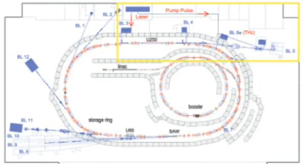
The 1.5-GeV synchrotron light source DELTA, operated by the TU Dortmund University, is shown schematically in Fig. 1. Besides dipole magnets as radiation sources, DELTA comprises two undulators (U55, U250) and a superconduct- ing asymmetric wiggler (SAW). The pulse duration of the synchrotron radiation is about 100 ps (FWHM) given by the bunch length. Shorter radiation pulses with durations in the sub-100-fs range can be generated with commercially available laser systems, but with wavelengths in the near- visible range. In the following, three techniques to combine the advantages of both radiation source types in order to produce radiation with short wavelengths as well as short pulse duration are described.
Coherent Harmonic Generation (CHG)
The CHG technique [1] is based on an interaction between a short laser pulse and an electron bunch. The setup consists of two undulators and a dispersive magnetic chicane between them. A detailed description of the CHG setup at DELTA can be found in [2]. The interaction occurs in the first un- dulator, the so-called modulator, and leads to a sinusoidal modulation of the electron energy with the periodicity of the
Figure 1: Sketch of the DELTA synchrotron radiation facility.
The yellow frame marks the CHG facility in the northern part of the storage ring.
∗Work supported by DFG, BMBF, FZ Jülich, and by the Federal State
†NRW.svenja.hilbrich@tu-dortmund.de
before after
modulation chicane chicane
modulator
modulator r adiator
laser laser
E/E (%)
z/ z/ z/
/0
Figure 2: Top: Sketch of the magnetic setup for EEHG. Cen- ter: The longitudinal phase space before the first magnetic chicane, before and after the second modulator, and after the second chicane. Bottom: The longitudinal electron density after the second chicane.
laser wavelength within a short "slice" at the center of the bunch. The magnetic chicane converts the energy modula- tion into a density modulation known as microbunching. In the second undulator, the radiator, the microbunches radiate coherently at the laser wavelength and harmonics thereof with a much higher intensity than the incoherent undulator radiation.
The power of the CHG radiation at thenth harmonic of the laser wavelength is [3]
Pn ∝N2b2n (1) withN being the number of modulated electrons and the so-called bunching factor
bn∝e−n2 (2) decreasing exponentially with the harmonic numbern.
Echo-enabled Harmonic Generation (EEHG)
The FEL seeding scheme EEHG [4] has been successfully tested at SLAC in Menlo Park (USA) [5] and SINAP in Shanghai (China) [6] and can also be applied at storage rings to generate ultrashort coherent pulses. Compared to CHG, it uses an additional undulator and chicane. As in the case of CHG, the electron energy is sinusoidally modulated in the first modulator, but the first chicane has a largerR56value, such that the electron distribution in the longitudinal phase space is strongly sheared while the density distribution is flat.
In the second modulator, the electron energy is modulated by a second laser pulse. In a following magnetic chicane with a moderate R56 value, a density modulation with a high content of harmonics is generated (see Fig. 2). The optimized bunching factor for EEHG, i.e., with optimum settings for each harmonic, scales as [7]
bn(λ)∝n−13 (3)
©2014CC-BY-3.0andbytherespectiveauthors
Modulator
U 250
ChicaneRadiatorU 250
Modulator 1Chicane 1 Modulator 2
Radiator Chicane 2
10 10
20 20 20 20
2.95 m
7.60 m 6.40 m
21.24 m 3.73 m
7
3 3
7
8.30 m
2.44 m Femtoslicing
Undulator
Figure 3: Top: Present magnetic setup in the northern part of DELTA. Bottom: Planned magnetic setup for the im- plementation of EEHG and femtoslicing in which two 3- and 7-degree dipole magnets are replaced by two 10-degree dipoles.
thus allowing the generation of higher harmonics with rea- sonable intensity compared to CHG.
Femtoslicing
In contrast to CHG and EEHG, femtoslicing [8] utilizes a geometrical separation of incoherent radiation from modu- lated and unmodulated electrons. Downstream of the modu- lator, a dispersive magnetic element, like a dipole magnet, creates the spatial separation of the electrons. In a follow- ing radiator, the off-energy electrons radiate incoherently at wavelengths to which the radiator is tuned. Femtoslicing is routinely performed at the ALS [9], at BESSY [10] and at the SLS [11].
DESIGN CONSIDERATIONS
In order to implement EEHG at DELTA, the CHG facil- ity in the northern part of the storage ring will be replaced by a new magnetic setup. The most challenging task for a successful operation of EEHG is to retain the resulting microbunches until they reach the radiator. Since dipole mag- nets would smear out the phase space structure, all EEHG components will be placed in one straight section. For that purpose, the 3- and 7-degree dipole magnets will be ex- changed by a 10-degree dipole magnet resulting in a long
Figure 4: Horizontal and vertical beta function and horizon- tal dispersion versus longitudinal positions(EEHG lattice).
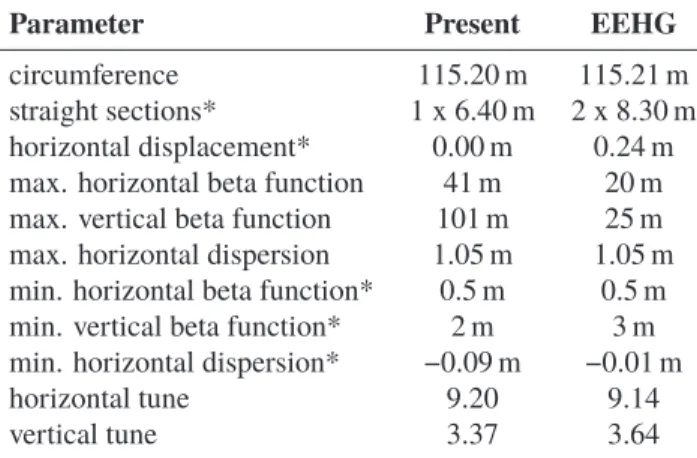
Table 1: Lattice Properties of the Present and EEHG Configuration. Parameters labeled by an asterix (*) refer to the CHG/EEHG section
Parameter Present EEHG
circumference 115.20 m 115.21 m
straight sections* 1 x 6.40 m 2 x 8.30 m horizontal displacement* 0.00 m 0.24 m max. horizontal beta function 41 m 20 m max. vertical beta function 101 m 25 m max. horizontal dispersion 1.05 m 1.05 m min. horizontal beta function* 0.5 m 0.5 m min. vertical beta function* 2 m 3 m min. horizontal dispersion* −0.09 m −0.01 m
horizontal tune 9.20 9.14
vertical tune 3.37 3.64
straight section with enough space for three undulators and two chicanes as shown in Fig. 3. In addition, there will be enough space for a femtoslicing undulator downstream of the 10-degree dipole magnet following the radiator.
Optical Functions
The new arrangement of the magnetic dipoles and quadrupoles leads to the optical functions shown in Fig. 4.
Simulations were performed using a modified version of the codeelegant[12]. The optical functions of the storage ring outside the range shown in Fig. 4 are identical to the present ones. Table 1 shows the properties of the lattices of the present and EEHG configuration. Another issue taken into consideration is to minimize the change of the circumfer- ence. For DELTA, a change of 1 cm is tolerable resulting in a horizontal displacement of the U250 axis by 24 cm towards the ring center (see Table 1).
Second-Order Effects
Considering an rms angular deviation ofσ= x/β0, wherexis the beam emittance andβ0the beta function at
©2014CC-BY-3.0andbytherespectiveauthors
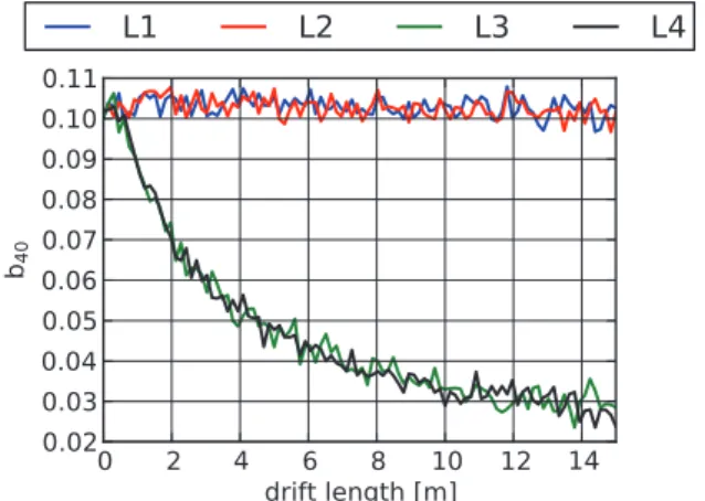
Figure 5: Schematic view of the lengths L1 to L4 between the components used for the EEHG setup.
Figure 6: Bunching factor forn= 40 versus the variation of the distances L1 to L4 shown in Fig. 5.
the beam waist, the resulting variation of path-lengths is [13]
ΔL=1 2x L
β0
(4) in a drift space of lengthL. This effect can destroy the mi- crobunching due to the various angular deviations of the electrons. For the planned EEHG setup at DELTA, the in- fluence of a variation of the distances L1 to L4 (see Fig. 5) between the undulators and chicanes on the bunching fac- tor was simulated using a self-written code. Each of the distances was varied from 0 to 13 m while the other ones re- mained zero. The calculation was performed for a horizontal beta function at the beam waist of 5 m and an emittance of 15 nm rad. As shown in Fig. 6, only the distance between the second undulator and the radiator (L3 + L4) has an influence on the transport of the microbunches as predicted by [14].
To reduce this effect, the second modulator and chicane will be placed as close as possible to the radiator.
NEW COMPONENTS
To implement EEHG at DELTA, two additional undula- tors and chicanes are required if the present U250 is used as radiator.
Undulators
Two new undulators (Fig. 7) were designed based on those used at FLASH for the ORS experiment [15]. The undulators are ordered and will be delivered this year. The design parameters of the new undulators and the U250 are listed in Table 2.
Figure 7: Sketch of the new undulators used in the EEHG setup (courtesy Scanditronix Magnet AB, Vislanda, Sweden).
Table 2: Parameters of the Undulators used in the Future EEHG Setup at DELTA
Parameter Modulators U250
pole gap 40 mm 50 mm
total length 1.85 m 4.85 m
period length 0.20 m 0.25 m
number of periods 7 17
magnetic peak field 0.62 T 0.76 T
Chicanes
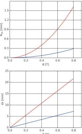
The strength of the second chicane is similar to that of the chicane in the present CHG setup while the first chicane has a much largerR56value of the order of 1 mm. A sketch with the dimensions of the first chicane is shown in Fig. 8. The parameters for both chicanes are listed in Table 3, and Fig. 9 shows the dependence of theR56value and the horizontal excursiondxon the magnetic fieldB.
Table 3: Parameters of the Chicanes in the EEHG Setup Parameter Chicane 1 Chicane 2
total length 1.5 m 0.9 m
length of single dipoles 0.30 m 0.15 m distance between dipoles 0.15 m 0.15 m
max. R56 1.6 mm 0.3 mm
max. magnetic field 0.8 T 0.8 T
offset dx 21 mm 7 mm
Figure 8: Schematic view of the first chicane. ©2014CC-BY-3.0andbytherespectiveauthors
Figure 9: Chicane strengthR56and horizontal excursiondx versus the magnetic field for the first (red) and second (blue) chicane in the new EEHG setup.
OPTIMUM LASER WAIST
In order to simulate the energy modulation of the electrons in the modulators, the propagation of the laser light can be described by a Gaussian beam determined by the wavelength λ, the waist positionz0, the Rayleigh lengthzrand the beam quality factorM2[16] which is 1 for the fundamental Gaus- sian mode and larger in the presence of higher-order modes.
By varying the waist position and Rayleigh length the energy modulation can be optimized.
Given an undulator of lengthLand a laser beam waist cen- tered at the undulator, a Rayleigh length ofzr ≈L/4 would maximize the energy modulation of an electron on the beam axis [17]. In order to include theM2factor and the finite electron beam size, the average energy modulation of the electrons was simulated with the codeelegant[12], which was modified to include anM2factor larger than unity [18].
The simulation was performed assuming an infinitely long laser pulse with the power corresponding to the peak power of a realistic laser pulse. The waist of the laser beam was located at the center of the undulator and the energy modula- tion was determinded under variation of the 1/e2laser waist radiusw0, which is related to the Rayleigh lengthzrby
zr =πw20/(λM2). (5) For the planned EEHG setup at DELTA, this dependency is shown in Fig. 10 for both modulators. The laser parameters
Figure 10: Energy modulation of the electrons versus laser waist radius (blue: first modulator, red: second modulator).
chosen for the simulation were anM2factor of 1.1, a laser wavelength of 800 nm, a laser pulse energy of 4 mJ and a pulse length (FWHM) of 60 fs. For both undulators, the max- imum energy modulation occurs for a waist radius of about 500 μm. Since the two modulators will be installed at loca- tions with different optical functions (see Fig. 3 and Fig. 4), the energy modulation in the second modulator is about 10%
higher. Given the optical functions, the simulation result shows that the Rayleigh length should bezr ≈L/1.6.
OUTLOOK
Since the positions of the undulators, chicanes and quadrupoles are specified, the next step will be to deter- mine the position of BPMs and steerer magnets. A new vacuum chamber design is under development, which will reuse as much as possible of the present chamber in order to minimize the costs.
ACKNOWLEDGMENT
It is a pleasure to thank our colleagues at DELTA and the faculty of Physics of the TU Dortmund University for their support. This work was supported by BMBF (05K13PE3), by the DFG (INST 212/236-1 FUGG), by the Helmholtz ARD Initiative, by the FZ Jülich and by the Federal State NRW.
REFERENCES
[1] R. Prazeres et al., "Coherent harmonic generation in the vac- uum ultraviolet spectral range on the storage ring ACO",Nucl.
Instr. and Meth. A272, pp. 68-72, 1988.
[2] S. Khan et al., "Generation of Ultrashort and Coherent Syn- chrotron Radiation Pulses at DELTA",Sync. Rad. News26, pp. 25-29, 2013.
[3] L.H. Yu, "Generation of intense uv radiation by subharmoni- cally seeded single-pass free-electron lasers",Phys. Rev. A 44, pp. 5178-5193, 1991.
[4] G. Stupakov, "Using the Beam-Echo Effect for Generation of Short-Wavelength Radiation",Phys. Rev. Lett.102, pp.
074801 ff., 2009.
©2014CC-BY-3.0andbytherespectiveauthors
[5] D. Xiang et al., "Demonstration of the Echo-Enabled Har- monic Generation Technique for Short-Wavelength Seeded Free Electron Lasers",Phys. Rev. Lett.105, pp. 114801 ff., 2010.
[6] Z.T. Zhao et al., "First lasing of an echo-enabled harmonic generation free-electron laser",Nature Photonics6, pp. 360- 363, 2012.
[7] D. Xiang et al., "Echo-enabled harmonic generation free electron laser",PRSTAB12, pp. 030702 ff., 2009.
[8] A.A. Zholents, M.S. Zolotorev, "Femtosecond X-Ray Pulses of Synchrotron Radiation",Phys. Rev. Lett.76, pp. 912-915, 1996.
[9] R.W. Schoenlein et al., "Generation of Femtosecond Pulses of Synchrotron Radiation",Science287, pp. 2237-2240, 2000.
[10] S. Khan et al., "Femtosecond Undulator Radiation from Sliced Electron Bunches",Phys. Rev. Lett.97, pp. 074801 ff., 2006.
[11] P. Beaud et al., "Spatiotemporal Stability of a Femtosecond Hard-X-Ray Undulator Source Studied by Control of Coher- ent Optical Phonons",Phys. Rev. Lett.99, pp. 174801 ff., 2007.
[12] M. Borland, Advanced Photon Source LS-287, 2000.
[13] R. Molo et al., "EEHG and Femtoslicing at DELTA", inProc.
35th Int. Free-Electron Laser Conf., New York, 2013, pp.
594-597.
[14] G. Penn, NGLS Technical Note 35, 2014.
[15] G. Angelova et al., "Results from the Optical Replica Experi- ment in FLASH", inProc.11th Europ. Particle Accelerator Conf., Genoa, 2008, pp. 1332-1334.
[16] A.E. Siegmann,Lasers, ISBN: 978-0935702118, Univ. Sci- ence Books, 1986.
[17] A. Amir, Y. Greenzweig, "Three-dimensional free electron laser gain and evolution of optical modes",Nucl. Instr. and Meth. A250, pp. 404-412, 1986.
[18] R. Molo, "Investigation of Short-Pulse Radiation Sources at DELTA Based on Coherent Harmonic Generation and Echo- Enabled Harmonic Generation", Diploma Thesis, faculty of Physics, TU Dortmund, Germany, 2011.
©2014CC-BY-3.0andbytherespectiveauthors