LOADING OF A PLASMA-WAKEFIELD ACCELERATOR SECTION DRIVEN BY A SELF-MODULATED PROTON BUNCH
V. K. Berglyd Olsen , E. Adli, University of Oslo, Norway
∗P. Muggli, Max Planck Institute for Physics, Munich, Germany L. D. Amorim, J. M. Vieira, Instituto Superior Technico, Lisbon, Portugal Abstract
We investigate beam loading of a plasma wake driven by a self-modulated proton beam using particle-in-cell simu- lations for phase III of the AWAKE project. We address the case of injection after the proton beam has already ex- perienced self-modulation in a previous plasma. Optimal parameters for the injected electron bunch in terms of ini- tial beam energy and beam charge density are investigated and evaluated in terms of witness bunch energy and energy spread. An approximate modulated proton beam is emulated in order to reduce computation time in these simulations.
INTRODUCTION
The AWAKE experiment [1] is a proof-of-principle demonstration of acceleration of an electron bunch to the TeV energy range in a single plasma section, using a proton bunch driver [2].
Figure 1: Simplified set-up of AWAKE Phase III. A long proton bunch experiences the SMI in a short plasma cell.
The electron bunch is injected before the second plasma cell.
The AWAKE experiment proposes using a proton driver at 400 GeV, delivered by the SPS. The experiment is currently under construction at CERN, scheduled to start in late 2016.
The SPS proton bunch is too long to generate a sufficiently strong wakefield [3]. A usable drive bunch needs to be close to the plasma wavelengthλpin length; however, producing a short enough proton bunch is technically difficult.
The plasma wavelength and frequency are given by
λp = 2πc
ωp , ωp =
Npe2
meε0, (1) whereNp is the plasma electron density,eis the elemen- tary charge,meis the electron mass andε0 is the vacuum permittivity.
A proton bunch withσz,0kp 1, whereσz,0is the initial length of the bunch, will under certain conditions develop a self-modulation instability (SMI) when it travels through a plasma [4]. The proton bunch will then develop into a train of micro bunches with a period on the order ofλp.
∗v.k.b.olsen@fys.uio.no
In phase I of the AWAKE experiment the SMI of the proton bunch will be studied. In phase II, the proton wake will be studied using a long, externally injected electron bunch that will sample all phases of the wake. In phase III, acceleration of a short bunch in the wake of an already self- modulated proton beam will be studied, as illustrated in Fig.
1. In this paper we study the beam quality of a short electron bunch accelerated by an SMI proton wake in preparation for phase III of AWAKE.
ξ [mm]
10 10.5 11 11.5 12 12.5 13 13.5 14
r [mm]
-0.15 -0.1 -0.05 0 0.05 0.1 0.15
Qtot PB = 12.11 pC Qtot
EB = -142.22 pC Ez < 163.5 MeV Er < 365.6 MeV
ξ [mm]
5 10 15 20 25 30 35
r [mm]
-0.5 0 0.5
Figure 2: Top: An example showing the structure of the plasma electrons (grey) with a projection of the proton beam (red) and the electron bunch (blue) density on the bottom.
TheEz(green) andEr(yellow) fields have been overlayed on the plot. Shown is also a sample of electron (blue) and proton (red) macro particles. Bottom: An example of a pre-modulated proton drive beam att=0 plotted in terms of charge density.
SIMULATION SET-UP
All simulations in this paper have been performed using OSIRIS, a three-dimensional, relativistic, particle-in-cell code for modelling plasma based accelerators [5].
The parameter scans presented have all been run on a small scale test case with a shorter proton drive beam than AWAKE specifications. We simulate here only the second plasma stage in Fig. 1, assuming a pre-modulated proton beam profile with charge density function
ρp+(ξ)=A
1 2√
2+cos
kpξ−μ1
e−r2/2σr, (2)
6th International Particle Accelerator Conference IPAC2015, Richmond, VA, USA JACoW Publishing
ISBN:978-3-95450-168-7 doi:10.18429/JACoW-IPAC2015-WEPWA026
3: Alternative Particle Sources and Acceleration Techniques A22 - Plasma Wakefield Acceleration
WEPWA026 2551
ContentfromthisworkmaybeusedunderthetermsoftheCCBY3.0licence(©2015).Anydistributionofthisworkmustmaintainattributiontotheauthor(s),titleofthework,publisher,andDOI.
whereAis a charge scaling factor,μ1is the centre position of the first micro bunch,kp =2πλ−1p is the wave number, andξ=z−ctis the coordinates in a frame moving at the speed of light.
The length of the beam is limited by a step function to 33 mm. Negative density values for the density profile is ignored by OSIRIS. This gives a beam of 26 micro bunches of protons, as seen in the bottom plot of Fig. 2. The beam has a total initial charge of 2.6 nC, with an initial peak current per micro bunch of 135 A. For the proton beamσr =200μm= 1.00 c/ωpin all simulations, wherec/ωpis the plasma skin depth.
The electron witness bunch is injected between micro bunches 20 and 21 of the drive beam, atξ≈12 mm, see Fig.
2. The charge density of the electron bunch is given by ρe−(ξ)=Ae−(ξ−μ)2/2σze−r2/2σr. (3) For the electron bunchσr =105μm=0.52 c/ωp, and σz =40μm=0.2 c/ωpin the cases with a short electron bunch. The plasma density at the beginning of the plasma section for all these simulations isNp =7×1014cm−3.
BEAM INJECTION
While the peak-to-peak distance between micro bunches of the self-modulated proton beam corresponds closely to the plasma wavelengthλp, it is not constant along the length of the beam [6]. A brief study of the SMI of both full scale and small scale proton beams, using Fourier transform and Wavelet analysis, revealed that the fundamental frequency was slightly lower than onekp.
kp/2π [ωp/c]
0.7 0.8 0.9 1 1.1 1.2 1.3
Amplitude
0 0.1 0.2 0.3 0.4 0.5 0.6
Self-modulated Pre-modulated
z [m]
0 2 4 6 8 10
ξ - ξ0 [μm]
-40 -30 -20 -10
0 Electron track
Proton track
Figure 3: Top: The Fourier transform of the proton beam after 10 m of plasma for a self- and pre-modulated beam.
The green line indicateskp = 2π/λp. Bottom: Typical drift of a proton and electron macro particle through the plasma in respect toc.
To minimise further SMI development with a pre- modulated beam, the micro bunch distance was reduced
to 0.9939kp, which produced a very good fit to the actual SMI for our test case, see Fig. 3.
An electron bunch of low MeV range initial energy will, due to its low gamma factor compared to the 400 GeV proton beam, slip backwards. In order to minimise this effect we set the initial energy of the electron bunch to 30 MeV, a little higher than AWAKE parameters. Typical slip for the beams through 10 m of plasma is illustrated in Fig. 3.
Staying in phase with the drive beam is essential to opti- mise energy transfer. Establishing an optimal injection point of the electron bunch was achieved by using bunches with length in the order of oneλp, and tracking a selection of the electrons with optimal energy gain back toz=0.
BEAM LOADING AND ENERGY SPREAD
In a plasma wakefield accelerator, the witness bunch should be accelerated at high efficiency while preserving a low energy spread. Beam loading in the linear regime can be calculated by the linear addition of fields. Only very narrow electron bunches, withσr c/ωp, can maintain low energy spread and emittance [7, 8].
Ez [MeV]
-400 -200 0 200 400
ÎEB = 42.55 A
Ez [MeV]
-400 -200 0 200 400
ÎEB = 134.55 A
Ez [MeV]
-400 -200 0 200 400
ÎEB = 425.50 A
ξ [mm]
10 10.5 11 11.5 12 12.5 13 13.5 14
Ez [MeV]
-400 -200 0 200 400
ÎEB = 1.35 kA
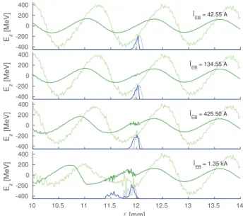
Figure 4: Comparison between the Ez field at 1 m (light green) and 10 m (dark green) of plasma for four different electron bunch currents. The fields are averages over a region 10−25μm from the axis. A dimensionless plot of the charge density of the electron bunch is added in blue.
In the non-linear blowout regime, the plasma electrons are blown out by the drive beam, leaving behind a uniform region of plasma ions. The ions pull the electrons back towards the axis, forming a bubble with length on the order of the plasma wavelength [8, 9]. In this regime, the charge and current profile required to optimally load the wake can be estimated analytically. Optimal loading results in a flatEzfield across the bunch with high wake to beam energy transfer efficiency.
There is a trade-off between the number of particles that can be accelerated and the accelerating gradient, as discussed in detail by Tzoufras et. al [10].
6th International Particle Accelerator Conference IPAC2015, Richmond, VA, USA JACoW Publishing
ISBN:978-3-95450-168-7 doi:10.18429/JACoW-IPAC2015-WEPWA026
WEPWA026 2552
ContentfromthisworkmaybeusedunderthetermsoftheCCBY3.0licence(©2015).Anydistributionofthisworkmustmaintainattributiontotheauthor(s),titleofthework,publisher,andDOI.
3: Alternative Particle Sources and Acceleration Techniques A22 - Plasma Wakefield Acceleration
The beam-plasma interaction studied in this paper has similarities with the above blowout regime, but the train of micro bunches produces a more complex wakefield [4]. We have studied the beam loading through simulations. Based on beam loading in the blowout regime, we use as starting point for the studies a witness bunch with the same peak current as the initial peak current of one proton micro bunch, 135 A. We then performed a scan with logarithmic steps of current from 13.46 A to 13.46 kA. A selection of these are shown in Fig. 4, significant loading of theEzfield does occur when the witness bunch has significantly higher current than the proton beam. An approximate flattening of the field is observed when the witness bunch current is about 3 times higher than the initial micro bunch current, as shown in Fig. 4c. For higher witness bunch currents, we observe that the field from the witness bunch itself starts to dominate the wake it experiences, as expected. The trailing part of the electron bunch is therefore decelerated, as shown for example in Fig. 4d.
We notice that constant loading as the drive and witness bunch propagate in the plasma is not possible, as protons keep being ejected radially throughout the plasma, eating up the micro bunches from the front. This leads to the energy gain levelling off after approximately 4 m of plasma, turning into energy loss as the dephasing between the electron bunch and theEz fields becomes too large. The phase difference ofEz at 1 m and 10 m is shown in Fig. 4. The mean energy gain (816.2 MeV) and relative energy spread (12%) of the electron bunch, as it travels through the plasma, is visible in blue in Fig. 5, showing a case with peak electron current of 425.5 A. The peak current of a micro bunch after 10 m of plasma, within one skin depth of the axis, is only 45 A.
z [m]
0 2 4 6 8 10
pz [GeV/c]
0 0.5 1
1.5 No Gradient
3.5% Gradient
No Gradient
ξ [mm]
11.8 11.9 12 12.1
pz [GeV/c]
0.6 0.8 1
1.2 3.5% Gradient
ξ [mm]
11.8 11.9 12 12.1
pz [GeV/c]
1.4 1.5 1.6 1.7 1.8
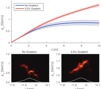
Figure 5: Top: Energy gain through 10 m of plasma for a short electron witness bunch withσz =40μm and ˆI = 425.5 A, for the case of no plasma gradient and 3.5% plasma gradient.Bottom: ξ−pzphase plot for both simulations at the end of the plasma.
PLASMA GRADIENT
Due to the backwards drift of theEz field, the electron bunch falls out of optimal phase after a few metres of plasma.
It is possible to stabilise the accelerating bucket by gradually increasing the plasma density. We performed a scan of plasma gradients ranging from 0% to 10% along 10 m of plasma, with a square bunch of lengthλp. We found that a gradient of 0.2−0.3×1014cm−3 (3−4%) per metre plasma for our initial density of 7×1014cm−3, produced the highest energy gain for the electrons with optimal phase.
By tracking some of these electrons back to their injection point, we could move the centre of the short bunch and do a new simulation comparing no gradient to a 3.5% gradient.
The best result was for a gradient with a density at 10 m of 7.245×1014cm−3 (3.5%), see Fig. 5 and Table 1.
Table 1: Electron Bunch Energy After 10 m of Plasma Energy No Gradient 3.5% Gradient
Mean 846.20 MeV 1618.77 MeV
RMS 101.23 MeV 54.93 MeV
RMS/Mean 11.96 % 3.39 %
CONCLUSION
We have studied beam loading of a SMI proton wake. A scan of electron witness bunch charges over three orders of magnitude revealed that a witness bunch peak current of about a factor 3 higher than the initial peak current of one proton micro bunch was optimal for flattening the wakefield.
It is important to note that protons keep getting ejected ra- dially, resulting in a loss of proton charge close to the axis, as the beam travels through the plasma. This decreases the current of a micro bunch by a factor of∼3 in the no gradient case.
The electron bunch does not stay in optimal phase for very long as the Ez field starts to drift significantly after 2−4 m of plasma. In most simulations the bunch ends up around the zero point of theEzfield, and the energy gradient flattens, and in some cases turns negative. For our optimal case of phase and charge, this effect could to a large degree be counteracted by a 3.5% gradient of the plasma, which forces a positive phase shift of the Ez field, keeping the electron bunch synchronous with the accelerating phase of the wake.
ACKNOWLEDGEMENT
The authors would like to acknowledge the OSIRIS Con- sortium, consisting of UCLA and IST (Lisbon, Portugal) for the use of OSIRIS, for providing access to the OSIRIS framework.
REFERENCES
[1] AWAKE Collaboration et al., Plasma Phys. Control. Fusion 56, 084013 (2014).
6th International Particle Accelerator Conference IPAC2015, Richmond, VA, USA JACoW Publishing
ISBN:978-3-95450-168-7 doi:10.18429/JACoW-IPAC2015-WEPWA026
3: Alternative Particle Sources and Acceleration Techniques A22 - Plasma Wakefield Acceleration
WEPWA026 2553
ContentfromthisworkmaybeusedunderthetermsoftheCCBY3.0licence(©2015).Anydistributionofthisworkmustmaintainattributiontotheauthor(s),titleofthework,publisher,andDOI.
[2] E. Gschwendtner et al., in Proceedings of IPAC2014 (2014), pp. 582–585.
[3] N. Kumar et al., Phys. Rev. Lett.104, 255003 (2010).
[4] A. Caldwell et al., Phys. Plasmas18, 103101 (2011).
[5] R. A. Fonseca et al., inComputational science — ICCS 2002, edited by P. M. A. Sloot et al., Lecture Notes in Computer Science 2331 (Springer Berlin Heidelberg, 2002), pp. 342–
351.
[6] J. Vieira et al., Phys. Plasmas19, 063105 (2012).
[7] T. Katsouleas et al., Part. Acc.22, 81–99 (1987).
[8] M. Tzoufras et al., Phys. Rev. Lett.101, 145002 (2008).
[9] W. Lu et al., Phys. Plasmas13, 056709 (2006).
[10] M. Tzoufras et al., Phys. Plasmas16, 056705 (2009).
6th International Particle Accelerator Conference IPAC2015, Richmond, VA, USA JACoW Publishing
ISBN:978-3-95450-168-7 doi:10.18429/JACoW-IPAC2015-WEPWA026
WEPWA026 2554
ContentfromthisworkmaybeusedunderthetermsoftheCCBY3.0licence(©2015).Anydistributionofthisworkmustmaintainattributiontotheauthor(s),titleofthework,publisher,andDOI.
3: Alternative Particle Sources and Acceleration Techniques A22 - Plasma Wakefield Acceleration