• Keine Ergebnisse gefunden

High Sensitivity Plasma Electron Density Measurements in Sources for a Proton-Driven Plasma Wakefield Accelerator

N/A
N/A
Protected

Academic year: 2021

Aktie "High Sensitivity Plasma Electron Density Measurements in Sources for a Proton-Driven Plasma Wakefield Accelerator"

Copied!
4
0
0

Wird geladen.... (Jetzt Volltext ansehen)

Volltext

(1)

High Sensitivity Plasma Electron Density Measurements in Sources for a Proton-Driven Plasma Wakefield Accelerator

R. Tarkeshian, O. Reimann, P. Muggli

Max-Planck-Institut für Physik, 80805 Munich, Germany

Abstract

The concept of proton-driven plasma wakefield acceleration has recently been proposed as a means of accelerating an electron bunch to high energies with very high average gra- dients (1 GeV/m). A demonstration experiment ( known as AWAKE) is now under devel- opment at CERN. One of the requirement for the experiment is a high plasma density uniformity. To diagnose the plasma density evolution radially and longitudinally the cut off frequency method is under study. The proposed measurement techniques, initial simu- lations, experimental setup and preliminary measurement results on Argon and Neon dis- charge sources are presented.

INTRODUCTION

Recently a new collaboration (known as AWAKE) was formed in order to demonstrate proton driven plasma wakefield acceleration at CERN for the first time [1]. In the proposed experiment the SPS proton bunch in CNGS facility is injected into a 10 m long plasma. The long proton bunch (σ =12 cm) travels in a dense plasma and undergoes a transverse instability called self- modulation instability (SMI) [2, 3]. Therefore a micro bunch train is generated that can then resonantly drive strong wakefields in the plasma. The electron bunch that is injected externally at the right phase of the wakefield is accelerated by fields on the order of 1 GV /m.

Plasma density uniformity lower than 1% along the beam path is necessary for the low en- ergy injected electrons to stay in the accelerating phase of the wakefield during propagation [4].

This cause need for transverse density measurements to explore the spatial homogeneity along the plasma channel. In the experiment the plasma density is also evolving as a function of time, which additionally sets the requirement for single-shot measurements with a time win- dow of maximum 100 ns. Standard methods for plasma density measurement such as Langmuir probe [5] and laser Thompson scattering [6] are not suitable for our application because of the relatively long integration time. The diameter of the expected plasma on the order of only few millimeters makes microwave interferometer also [7] not applicable.

40

th

EPS Conference on Plasma Physics P4.210

(2)

PLASMA DENSITY MEASUREMENT USING CUTOFF METHOD

To fulfill the above-mentioned requirements, we are investigating the measurement of the plasma cutoff frequency to determine the electron density. In a plasma the natural oscillation frequency of the free electrons is related to their density by ω p =

q n

e

e

2

ε

0

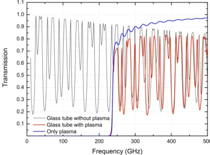
m where n e is the free electron density and m and e are the electron mass and charge, respectively. For plasma densities in the expected order of magnitude of 10 14 − 10 15 cm −3 this frequency is in the 90 − 300GHz range. Below the oscillation frequency the plasma is opaque (cut-off) and it is transparent for higher frequencies. The spectrum of broadband THz waves passing through the plasma in the transverse direction exhibits a cut-off at the plasma frequency from which the plasma density can be determined. In our case the plasma is contained in a glass tube (5 mm inner diameter, 2 mm wall thickness) and its contribution to the transmitted spectrum must be taken into ac- count. By using the method of impedance transformation with multiple dielectrics layers the power reflection and transmission spectra can be calculated. The influence of electron temper- ature, collision frequency, electron density, thickness and profile of the plasma and glass tube on the observed cutoff can be modeled numerically [8]. The effect of glass tube on transmitted waves with a plasma n e = 7 × 10 14 cm −3 using a simplified model is shown in Fig. 1 .

Figure 1: Calculated transmission spectrum of a plasma column contained within glass tube.

For a sensitivity of better than 1% in terms of plasma density the frequency spectrum (or cut- off frequency) must be measured with a resolution of about 500 MHz for a 10 14 cm −3 plasma.

One of the challenges in our experiment is to generate and span a THz spectrum around the cutoff frequency and detect it with the necessary resolution within about 100 ns.

Two different techniques for broadband THz radiation generation are proposed: chirped con-

40

th

EPS Conference on Plasma Physics P4.210

(3)

tinuous wave photomixing (CCWP) [9] and THz time domain spectroscopy (THz-TDS) [10].

EXPERIMENTAL SETUP AND PRELIMINARY MEASUREMENT RESULTS

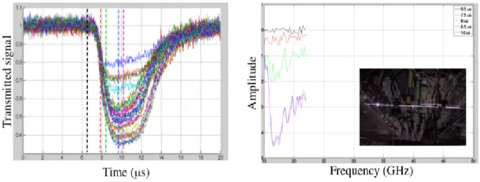
For a first test of time resolved cut-off measurement in a thin (<5 mm) plasma channel a trans- mission setup using a standard RF generator and spectrum analyzer (up to 22GHz) is used. The horn antenna on opposite sides of the plasma channel are used to optimize the wave coupling from emitter to the receiver through the plasma. A measurement on Argon plasma discharge source (n e ≈ 1.5 × 10 13 cm −3 , f p ≈ 35 GHz) is shown in Fig. 2. On the left, time resolved trans- mission signals separated in different colors, each representing another frequency are shown.

On the right hand side, the extracted transmission spectra at some certain times corresponding to different plasma channel diameters are plotted. The measurements are limited by the generator frequency range, but the frequency cutoff can be clearly identified.

Figure 2: Transmitted signal through Argon discharge source.

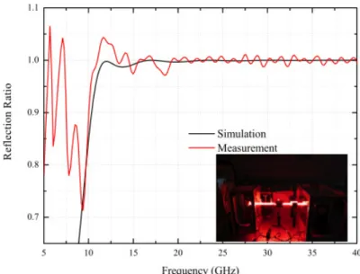
In the next test a RF network analyzers system (< 40 GHz) is used to measure the magnitude and phase of the reflected wave at a thin DC Neon discharge source (n e ≈ 10 12 cm −3 , f p ≈ 9 GHz). The ratio of the reflected power with plasma on and off is shown in Fig. 3.

The measured cutoff frequency is in a very good agreement with the prediction from the model calculation. Below the cutoff frequency the measured spectrum is dominated by impedance effects over the length of the waveguide. Due to limitation in the frequency range of conven- tional RF generators and analyzers and to the relatively high cost of those devices, we are studying the CCWP concept described in [9]. Two diode lasers with central frequencies at (193 THz±125 GHz) and (193.2 THz±125 GHz) are used to generate frequencies up to 450 GHz.

As a first demonstration a chirped signal spectrum with a bandwidth of 6 GHz (oscilloscope lim- itations) within 50 µ s is generated. A low pass filter with a cutoff of 2 GHz (analog to cut-off plasma frequency) is measured and the transmitted spectrum is shown in Fig. 4.

40

th

EPS Conference on Plasma Physics P4.210

(4)

Figure 3: Ratio of reflected microwave signals at a Neon discharge source.

Figure 4: Transmission of waves created by a CCWP setup through a low-pass filter (2 GHz cutoff).

SUMMARY

Stepwise experiments towards a high resolution, single shot, broadband plasma frequency measurement are in progress and first results were presented. It is shown that the cut-off mea- surement method is also applicable to thin plasma channels. As a next step a full CCWP system as well as a THz-TDS system will be developed and tested.

References

[1] P. Muggli et. al., IPAC Proceedings, (2013)

[2] N. Kumar et. al., Phys. Rev. Lett. 104, 255003 (2010)

[3] A. Caldwell, K. Lotov, A. Pukhov, and F. Simon, Nature Physics 5, (2009) [4] K. V. Lotov, et. al., Phys. Plasmas 20, 013102 (2013).

[5] I. Langmuir and H. Mott-Schmidth, Gen. Electr. Rev 27 449 (1924)

[6] E. R. Kieft, C. H. j. M. Groothuis, et. al., Rev. Sci. Instrum. 76, 093503(2008) [7] C. Deline, B. E. Gilchrist et. al., Rev. Sci. Instrum. 78, 113504 (2007)

[8] C. Yuan, Z. Zhou., et. al., NIM in Physic Research B, 269, (2011) [9] R. Tarkeshian, O. Reimann, P. Muggli, AIP Conf. Proc. 1507, 2012 [10] M. C. Nuss, J. Orenstein, Topics in Applied Physics, 74 (1998)

40

th

EPS Conference on Plasma Physics P4.210

Abbildung

Figure 1: Calculated transmission spectrum of a plasma column contained within glass tube.
Figure 2: Transmitted signal through Argon discharge source.
Figure 3: Ratio of reflected microwave signals at a Neon discharge source.

Referenzen

ÄHNLICHE DOKUMENTE

In all previous tests the method of truncated Taylor series expansion applied on the relativistic Newtons equation of motion for charged particles demonstrated for all selected

W peak PlaTo = 0.79 GeV. The spectrometer in its current configuration cannot deliver reliable quantitative information about energy spread. Since the witness-bunch energies are

Among the main advantages of this acceleration scheme are the high accelerating fields up to tens of GV/m, that can be achieved [ 41 ] and the high possible energy gain in a

To obtain a full picture of the acceleration process, together with the evolution of crucial quality parameters such as emittance and energy spread, the beam setup which uses a

Capillary-discharge plasmas allow for shaped longitudinal density profiles through the capillary design while laser-induced plasmas allow for transverse shaping of the density

[197] Ronald D Ruth, PL Morton, Perry B Wilson, and AW Chao. A plasma wake field accelerator. Brunetti, et al. A compact syn- chrotron radiation source driven by a

Die Behandlung mit PRP/ACP ist eine jüngere Entwicklung, die mit großem Erfolg in der Orthopädie eingesetzt wird.. Das Besondere: Das PRP/ACP wird autolog, also aus Ihrem eigenen

G Wenn zwei oder mehr Sprachen ausgestrahlt werden, können Sie die Sprache über die Taste I/II auf der Fernbedienung auswählen. G Drücken Sie D oder E , um die gewünschte