DESIGN OF A TeV BEAM DRIVEN
PLASMA WAKEFIELD LINEAR COLLIDER ∗
E. Adli , University of Oslo, Norway †
J.P. Delahaye, S.J. Gessner, M.J. Hogan, T. Raubenheimer, SLAC, Stanford, USA W. An, W. Mori, C. Joshi, UCLA, Los Angeles, USA, P. Muggli, MPP, Munich, Germany Abstract
A novel design of a 500 GeV c.m. beam-driven PWFA lin- ear collider with effective accelerating gradient on the order of 1 GV/m and extendable in the multi-TeV energy range is presented.
The main bunches collide in CW mode at several kHz repetition frequency. They are accelerated and focused with several GV/m fields generated in plasma cells by drive bunches with very good transfer efficiency. The drive bunches are themselves accelerated by a CW superconducting rf recirculating linac. We consider the overall optimizations for the proposed design, compare the effi- ciency with similar collider designs like ILC and CLIC and we outline the major R&D challenges.
INTRODUCTION
Accelerating gradients in beam-driven plasmas of more than 50 GV/m have been demonstrated experimentally [1].
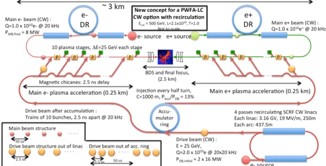
We base the collider design on adopting parameters sim- ilar to ILC for the main beams and assuming a 25 GeV main bunch energy gain per plasma stage of on the order of one meter length, and a resulting effective gradient of 1 GV/m. Our concept for a PWFA-based Linear Collider is shown schematically in Fig. 1 with key parameters pro- vided in Table 1. We adopt established concepts for the beam generation and focusing systems, taking advantage of the extensive R&D for conventional rf linear colliders dur- ing the last twenty years, especially ILC [2] and CLIC [3], with a potential for a comparably lower power consump- tion and cost. The acceleration in plasma is a single bunch process, and this provides flexibility in the interval between bunches. In the preferred scheme the main bunches collide in CW mode at several kHz repetition frequency (unlike the ILC which collides bunch trains at 5 Hz). The main bunches are accelerated and focused in multi-GV/m fields generated in plasma cells powered by drive bunches with high transfer efficiency. The drive bunches are acceler- ated by a CW superconducting rf recirculating linac tak- ing advantage of the impressive progress of the rf technol- ogy developed by ILC and providing an excellent power efficiency with a high flexibility in the number of bunches.
The CW-mode operation is advantageous from the point of view of both the plasma source and the accelerator com- plex. However, the time structure of the PWFA-LC could also be adapted for pulsed mode operation, without signif- icant reductions of the efficiency of the accelerator com- plex. This could open the possibility of an ILC energy up-
∗
This work is supported by the Research Council of Norway and U.S.
Department of Energy under contract number DE-AC02-76SF00515.
†
Erik.Adli@fys.uio.no
grade to multi-TeV energy range without significant mod- ifications to the ILC facility. Our concept differs signifi- cantly from the work presented in [4] in particular by the SCRF based drive beam generation, the CW operation, the co-linear drive beam distribution and more detailed power calculations.
The 500 GeV design has main beam parameters as close as possible to ILC at 500 GeV thus taking advantage of the design and R&D effort already performed in the frame of ILC. Some changes to the main beam parameters have been made; they are: charge per bunch of 1x10
10(2x10
10in ILC), bunch length of 20 μm imposed by plasma con- straints (300 μm in ILC), 20,000 bunches per second in- stead of 12,500 in ILC to compensate for the luminosity re- duction induced by lower charge per bunch, vertical focus- ing of the beam at IP with β
y= 0.1 mm as in CLIC instead of 0.48 mm in ILC taking advantage of the reduced charge per bunch. As a consequence the vertical beam size at IP is reduced from 5.9 to 2.7 nm. Finally the total luminosity and luminosity in 1% of the peak energy are 2.1x10
34/cm
2/s and 1.3x10
34/cm/s respectively, slightly larger than in ILC in spite of a somewhat larger beamstrahlung (a disruption parameter of δ
b= 0.07 instead of 0.04, but still in the low beamstrahlung regime).
PLASMA OPTIMIZATION
The present design assumes an energy gain of 25 GeV per stage and a main beam bunch charge of 10
10parti- cles. We present here an optimization based on PWFA of an e
−driver and an e
−witness bunch (the main beam) in the blow-out regime, for which it has been demonstrated that the beam loading efficiency can exceed 90% for shaped trailing bunches while maintaining low energy spread and emittance [5]. The results assume the plasma ions do not move. The drive beam parameters are considered as free variables, used to minimize the main beam energy spread, maximize the drive beam to main beam energy transfer ef- ficiency, minimize power consumption and minimize the drive beam energy. The plasma density of 2x10
16/cm
3has been minimized with the constraint of still yielding 25 GeV energy gain per cell for an acceptable plasma cell length (3.3 m). By adjusting the ratio of the main bunch to drive bunch charge, for a given distance between the two bunches, the beam loading of the main bunch flattens the wake field for uniform acceleration along the bunch length [5]. The distance between the two bunches determines the ratio of the flat part of the accelerating field to the peak Proceedings of IPAC2013, Shanghai, China TUPME020
01 Circular and Linear Colliders A16 Advanced Concepts
ISBN 978-3-95450-122-9
1613 Copyright c ○ 2013 by J A C oW — cc Cr eati v e Commons Attrib ution 3.0 (CC-BY -3.0)
Figure 1: Layout of a 500 GeV PWFA Linear Collider. Each main bunch is accelerated by 25 GeV in each of ten plasma stages. The plasma is driven by e
−bunches, generated by a SCRF CW recirculating linac, and distributed co-linearly with the main beams.
decelerating field; the transformer ratio. We design for a transformer ratio of 1
1. A transformer ratio higher than 1 would reduce the drive beam energy, but tighten the main bunch injection tolerances, as the main bunch needs to be positioned closer to the trailing edge of the bubble. Using Gaussian beam current profiles, the optimization yields [6]
a drive bunch charge of 2x10
10, drive bunch length of 40m (approx. the plasma wavelength/2 π ), a distance between the drive bunch and the main bunch of 187 um and a final main bunch energy spread of a few %. Assuming opera- tion in the PWFA blow-out with the stated parameters and electron bunches with a Gaussian charge profile, an over- all drive bunch to main bunch power transfer efficiency of 50% is achieved in QuickPIC [7] simulations. The drive to plasma transfer efficiency is 77% and the plasma to main bunch transfer efficiency is 65% [6]. For positron accel- eration other regimes such as the near hollow channel pro- posed most recently by [8] shows promise, however precise efficiency calculations have not yet been performed for this regime.
DRIVE BEAM GENERATION
The plasma cells are powered by trains of bunches pro- duced using recirculating linac acceleration. Each drive bunch powers one single plasma cell accelerating one sin- gle main bunch by 25 GeV, and is then ejected to a dump.
The process starts with a CW SC linac for optimum effi- ciency and a recirculating beam line to reduce the overall drive beam linac length and the associated cost and cryo- genics power. The bunches are fed into an accumulator ring to generate the time structure required to power the
1
![Table 1: PWFA-LC parameters for 500 and 3,000 GeV. Pa- Pa-rameters are also available for 250 and 1,000 GeV [9].](https://thumb-eu.123doks.com/thumbv2/1library_info/4018955.1541623/3.889.455.810.118.764/table-pwfa-parameters-gev-rameters-also-available-gev.webp)
