AWAKE, THE PROOF-OF-PRINCIPLE R&D EXPERIMENT AT CERN M. Bernardini, T. Bohl, C. Bracco, A. Butterworth, S. Cipiccia, H. Damerau, S. Doebert, E. Gschwendtner, V. Fedosseev, E. Feldbaumer W. Hofle, A. Pardons, A. Petrenko, J. Schmidt,
M. Turner, H. Vincke, CERN, Geneva, Switzerland P. Muggli, MPP Munich, Germany
Abstract
The Advanced Proton Driven Plasma Wakefield Acceleration Experiment (AWAKE) is a proof-of- principle R&D experiment at CERN. It is the world’s first proton driven plasma wakefield acceleration experiment, using a high-energy proton bunch to drive plasma wakefields for electron beam acceleration. The AWAKE experiment will be installed in the former CNGS facility and will use the 400 GeV proton beam bunches from the SPS, which will be sent to a plasma source. An electron beam will be injected into the plasma cell to probe the accelerating wakefield. Challenging modifications in the area and new installations are required for AWAKE. First proton beam to the experiment is expected late 2016. The accelerating electron physics will start late 2017.
This paper gives an overview of the project from physics and engineering point of view, it describes the main activities and the milestones.
INTRODUCTION
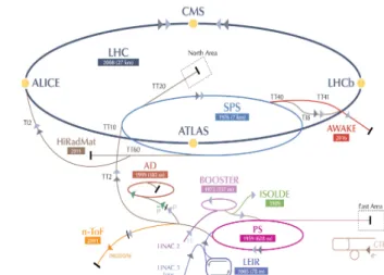
In the baseline design of the AWAKE experiment at CERN, an LHC-type proton bunch of 400GeV/c (but with higher intensity of 3 ⋅ 1011 protons/bunch) will be extracted from the CERN SPS (see Fig. 1) and sent along the 750m long proton beam line towards a plasma cell, which will be installed in the former CNGS area.
Figure 1: Layout of the CERN accelerator chain.
The proton beam will be focused to σx,y = 200 µm near the entrance of the 10 m long Rubidium vapour plasma cell with an adjustable density in the 1014 - 1015 cm-3 range. When the proton bunch with an rms bunch length of σz = 12 cm (400 ps) enters the plasma cell, it undergoes the self-modulation instability (SMI) [1] i.e.
the development a long bunch of protons into a series of micro-bunches that resonantly drive large wakefields. The effective length and period of the modulated beam is set by the plasma wavelength (for AWAKE typically λpe = 1mm). A high power (~4.5 TW) laser pulse [2] co- propagating and co-axial with the proton beam, will be used to ionize the neutral gas in the plasma cell and also generates the seed of the proton bunch self-modulation.
Several diagnostics tools [3] will be installed downstream of the plasma cell to measure the proton bunch self- modulation effects. In the AWAKE master schedule the experimental evidence for the self-modulation instability corresponds to Phase 1, which foresees the following milestones: installation during 2015 until Q1 2016, hardware and beam commissioning in Q2/Q3 2016 and physics from Q4 2016.
In Phase 2 AWAKE aims at the first demonstration of proton driven plasma wakefield acceleration of an electron witness beam; an electron beam of 1.2 ⋅ 109 electrons, which will be injected at 10 – 20 MeV/c into the plasma cell, will serve as witness beam and will be accelerated in the wake of the proton bunch and the accelerated electron bunch properties will be measured with an electron spectrometer. In Phase 2 the milestones are: installation during Q1 and Q2 2017, alternate with SMI physics, hardware and beam commissioning from Q3 to Q4, Physics from Q1 until the start of the CERN Long Shutdown 2 in Q3 2018.
AWAKE AT CERN
The AWAKE experiment is installed in the former CNGS facility. The conversion of the CNGS area into the AWAKE area started in January 2014 and challenging modifications are currently put in place. The following chapters describe the different activities and status of the systems of the AWAKE facility.
Proton Beam Line
The existing CNGS proton beam line is modified only in its last ~80 m, i.e. in the matching section and in the final focusing part in order to comply with the AWAKE requirements. The laser beam is merged with the proton beam at a distance of ~20 m from the plasma cell by adding a proton beam chicane to integrate the laser mirror. An offset of 19.9 mm exists between the proton and the laser beam axis, enough clearance to avoid intercepting protons and inducing losses. The proton and laser beams are made co-axial over the full length of the plasma cell, in particular the 3 σ proton beam envelope (~0.6 mm) must be contained in the 1σ laser spot size (~1 MOAC1 Proceedings of IPAC2015, Richmond, VA, USA
ISBN 978-3-95450-168-7 34
Copyright©2015CC-BY-3.0andbytherespectiveauthors
3: Alternative Particle Sources and Acceleration Techniques A22 - Plasma Wakefield Acceleration
mm). A pointing precision of 100 µm is required at the cell entrance resulting in a maximum angular error of 15 µrad for the proton beam line. To achieve this the ripple in the current of the main dipole power converter is kept below 510-4. A 0.2 mm thick aluminium window will be installed in the proton beam line to separate the SPS and the AWAKE vacuum. A negligible energy deposition (5 J/cm3) and maximum temperature increase (2.5 K) were calculated at the aluminium window; the quality of the window is not compromised. Modifications and new beam diagnostics are required at the end of the proton beam line; the electronics of the beam position monitors is modified to allow for single bunch measurements. Two BTVs located about 1 m up and downstream of the plasma cell, will perform profile and position measurements and will also be used during setup to align the proton and laser beam. The synchronization between the two beams will be adjusted with a streak camera connected to a BTV, located ~2 m upstream the plasma cell.
Figure 2: Integration of the AWAKE experiment in the experimental area.
Laser Beam Line
The CNGS storage gallery is modified to become a dust-free (over-pressurized) and temperature stabilized area to house the laser system [2]. Due to the small size of the gallery, the integration of the laser, pulse compressor, laser beam transport optics, laser tables, racks and clean room features such as a special cooling & ventilation system, double door access system is very challenging, but has been successfully implemented and the installation is ongoing. Two laser beams are to be transported from the laser room: The first one is used for plasma production and seeding of the SMI in the proton bunch. For that aim a 4 m long laser core (50 cm diameter) was drilled between the laser room and the proton beam line tuning. As the peak power of the 100 fs compressed laser pulse is very high, the injection of the laser beam into the vacuum system of the SPS proton beam must be done before laser pulse compression.
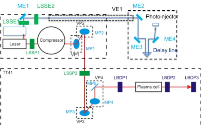
Therefore the vacuum laser beam line connecting the laser with the proton merging area has to fulfill the requirements of the SPS vacuum system (10-7 mbar) resulting in a demanding design for the laser line optics and vacuum system (see Fig 3). The second laser beam is required for the generation of the electron beam and has to be transported to the electron source.
Figure 3: Functional scheme of the main laser lines.
LSSP#: Laser Safety Shutter for p+ and e- beam lines.
LBDP#: Laser beam dumps for p+ beam line. MP#:
Mirrors for p+ beam lines in vacuum. ME#: mirrors for e- beam line. VP#, VE1: vacuum vessels for p+ and e- lines.
Electron Source
The PHIN injector built for CTF3, which will have completed its experimental program for CLIC at the end of 2015, fulfils the baseline electron beam requirements (10-20 MeV/c, 1.2E9 electrons/bunch, σz=4 ps, σx,y = 250 µm at focus, εnorm = 2 mm mrad) and will be used as electron-source for the AWAKE experiment. The electron source consists of a metal photocathode housed in a 2.5- cell normal conducting RF cavity, a load-lock system for cathode exchange, a 3 GHz booster accelerator to boost the energy to the required 20 MeV/c and electrical and optical diagnostics (BPMs, Fast Current transformer, Faraday Cup and screens for emittance and spectrometer measurements). In addition the klystron and modulator system will be recuperated from CTF3 providing the 3 GHz RF power. The majority of the components for the electron source exists at CERN. However, the parameters of the system must be modified, tested and designed in such a way that at a later stage higher intensities (1nC) and shorted bunch length (< 1ps) can be provided.
Electron Beam Line
A new 15 m long electron beam line has been designed to transport the electron beam from the RF gun, across a newly built tunnel (7 m long, 2.5 m wide), towards the proton beam line to be injected into the plasma cell on the same axis as the proton and laser beam. In order to comply with the experimental requirements the electron beam optics must provide a flexible design to allow varying the focal point by up to 6 m inside the plasma cell [4]. The proton and the electron beams share the last ~5 m of the line upstream of the plasma cell. The technical parameters for the new magnets (4 dipoles, 11 quadrupoles and 11 correctors) have been specified so that the market survey of these new magnets can be launched. In addition specifications were defined for the electron beam line diagnostics; e.g. the BPMs should be able to measure the position of electrons in the presence of the AWAKE proton beam at the same time. A peak-to- peak resolution of 50 µm is required. The electron beam
Photoinjector
LSSE2 VE1
LSSE1
ME1 ME2
ME3
ME4
THG$
Delay line
Proceedings of IPAC2015, Richmond, VA, USA MOAC1
3: Alternative Particle Sources and Acceleration Techniques A22 - Plasma Wakefield Acceleration
ISBN 978-3-95450-168-7 35 Copyright©2015CC-BY-3.0andbytherespectiveauthors
shall be synchronized with the proton and laser beam at a
<1 ps level, and will be measured with a streak camera linked to a BTV. To meet the performance criteria of the light transmission system a straight line between the beam screen and the camera was required, which implied the excavation of a ~4 m long 15 cm diameter core between the proton line and the electron source area, where the streak camera will be installed.
Synchronisation
Synchronization between laser pulse and electron beam at the level of a few tens of femtoseconds (a fraction of the plasma period of ~4 ps) is required for the deterministic injection of the witness bunch into the plasma wakefields.
This is achieved by driving the RF-gun of the electron source with a laser pulse derived from the same laser system as used for plasma ionization and seeding. The synchronization between the proton and the laser beam must be better than 100 ps, i.e. better than the rms proton bunch length of ~400 ps. The laser mode-locker (fML = 88.17 MHz) cannot follow the relative revolution frequency change through the SPS acceleration cycle, and therefore the proton bunch in the SPS must be synchronized to the AWAKE reference prior to extraction.
A low phase-noise RF source at 3 GHz is made the master to which the 34th harmonic of the laser oscillator (at fML) is locked. Lower frequencies for fast triggers (176.3 MHz), SPS synchronization (8.68 kHz) and laser/electron beam repetition rate (10 Hz) are derived by integer division from the master oscillator. Only the 200 MHz RF for the synchronization with the SPS requires a fractional divider.
A system is foreseen that allows to exchange the synchronization signals on ~3 km long fibres between the AWAKE facility and SPS RF Faraday Cage in BA3; the jitter and drift of the signal transmission has been verified to not exceed the picosecond range, slow variations will be compensated by a feed-back loop.
Experimental Area
The 10 m long Rubidium vapour plasma source will be installed at the end of the proton beam line at a slope of 6% (originating from the CNGS beam direction towards Italy). The Rb vapour with density of 1014- 1015 cm-3 is created in an oil heat exchanger and can accommodate either a very uniform constant density or a density gradient. The density is reached at oil and vapour temperatures between 150° and 200°C [3]. The plasma density falls off at the ends of the cell when fast valves open, which are currently foreseen. While this has no impact on the self-modulation instability of the proton beam, it will require further studies concerning electron injection and capture. The first 10 m Rubidium vapour plasma cell prototype will be delivered to CERN in June 2015. The final plasma cell will be delivered in October 2015. Tests on the temperature uniformity, operation with
Rubidium, and fast-valve effects will be performed in a test-area on surface.
Self-modulation instability diagnostics are integrated downstream the plasma cell and are based on measuring the radiation emitted by the micro-bunches when traversing a dielectric interface (OTR and CTR effect).
Details of these detectors are described in [3]. Another way is to detect the SMI effect by measuring the angular divergence of the proton beam caused by the SMI in the plasma cell, which is at the order of ~1mrad. For this purpose the bunch profile is measured at two different scintillator screens installed downstream the plasma cell and at a distance of ~8 m with a resolution of ~0.1 mm.
With this method the saturation point of the SMI inside the plasma cell can also be measured, at a 2% level.
The electron spectrometer system consists of a C-shaped magnet providing a 1.5 T field to separate the electrons from the proton beam and disperse them in energy. The electrons impinge on a scintillating screen (baseline is GadOx) and an optical line will transport the screen light to a camera. Both the SMI diagnostics as well as the electron spectrometer system use Commercial Off-the- Shelf (COT) cameras, which are highly sensitive to radiation and which therefore must be installed at a distance from the beam line in a radiation-free area. The light transmission has to be carefully optimised.
Issues of integration and performance of the detector systems are interleaved and currently studied. Radiation protection and radiation to electronics calculations were performed and show that by installing additional shielding in the experimental area, an appropriate area can be prepared for sensitive equipment such as streak cameras and RF components.
CONCLUSION
The preparation of the AWAKE facility is progressing well. The area has been cleared from CNGS equipment and is currently prepared for the AWAKE experiment;
Civil engineering for the electron tunnel, the laser core and the streak camera light core is finished, the clean room for the laser is currently being modified; the proton and electron beam line is designed and the parameters frozen; indirect self-modulation measurement studies are advancing well; the installation of services and infrastructure is ongoing and the integration of the electron source is well advanced. The experimental equipment will be installed by end 2015, with hardware and beam commissioning planned for the first half of 2016, so that first proton beam for physics to the plasma cell is ready for October 2016.
REFERENCES
[1] N. Kumar, A. Pukhov and K. Lotov, Phys.Rev.Lett 104, 255003 (2010).
[2] Joshua T. Moody et al., “Laser Propagation Effects during Photoionization of Meter Scale Rubidium MOAC1 Proceedings of IPAC2015, Richmond, VA, USA
ISBN 978-3-95450-168-7 36
Copyright©2015CC-BY-3.0andbytherespectiveauthors
3: Alternative Particle Sources and Acceleration Techniques A22 - Plasma Wakefield Acceleration
Vapor Source”, WEPWA0066, these proceedings, IPAC’15, Richmond, USA (2015).
[3] P. Muggli “The AWAKE Proton-Driven Plasma Wakefield Experiment at CERN”, WEPWA007, these proceedings, IPAC’15, Richmond, USA (2015).
[4] J.S. Schmidt et al., “The AWAKE Electron Primary Beam Line”, WEPWA039, these proceedings, IPAC’15, Richmond, USA (2015).
Proceedings of IPAC2015, Richmond, VA, USA MOAC1
3: Alternative Particle Sources and Acceleration Techniques A22 - Plasma Wakefield Acceleration
ISBN 978-3-95450-168-7 37 Copyright©2015CC-BY-3.0andbytherespectiveauthors