SUPPRESSION OF FEL LASING BY A SEEDED MICROBUNCHING INSTABILITY
∗C. Lechner
†, A. Azima, M. Drescher, L. L. Lazzarino, Th. Maltezopoulos, V. Miltchev, T. Plath, J. Rönsch-Schulenburg, J. Rossbach, University of Hamburg, Hamburg, Germany
K. E. Hacker, S. Khan, R. Molo, DELTA, TU Dortmund University, Dortmund, Germany S. Ackermann, J. Bödewadt, G. Brenner, M. Dohlus, N. Ekanayake, T. Golz, T. Laarmann,
T. Limberg, E. Schneidmiller, N. Stojanovic, M. Yurkov, DESY, Hamburg, Germany
Abstract
Collective effects and instabilities due to longitudinal space charge and coherent synchrotron radiation can de- grade the quality of the ultra-relativistic, high-brightness electron bunches driving free-electron lasers (FELs). In this contribution, we demonstrate suppression of FEL lasing induced by a laser-triggered microbunching instability at the free-electron laser FLASH. The interaction between the electron bunches and the 800-nm laser pulses takes place in an undulator upstream of the FEL undulators. A significant decrease of XUV photon pulse energies has been observed in coincidence with the laser-electron overlap in the modulator.
We discuss the underlying mechanisms based on longitu- dinal space charge amplification (LSCA) [1] and present measurements.
INTRODUCTION
The microbunching instability (MBI) due to longitudinal space-charge (LSC) forces in linear accelerators can compro- mise the quality of high-brightness electron bunches. This affects electron beam diagnostics as well as the FEL perfor- mance. For instance, emission of coherent optical transition radiation (COTR) was observed at several facilities [2–5]
and it has to be mitigated for accurate measurements of the transverse beam profile. The longitudinal space-charge am- plifier (LSCA) proposed in Ref. [1] is a concept to exploit these instabilities for the production of short-wavelength radiation. As illustrated in Fig. 1, an LSCA comprises mul- tiple amplification stages, each one consisting of an electron beamline followed by a dedicated dispersive element. In the
∗Work supported by Federal Ministry of Education and Research of Germany under contract No. 05K10PE1, 05K10PE3, 05K13GU4, 05K13PE3, and the German Research Foundation program graduate school 1355.
†christoph.lechner@desy.de Electron
beamline
Chicane
Stage 1 Stage 2
Electron beamline
Chicane
Figure 1: Schematic layout of a two-stage longitudinal space- charge amplifier (LSCA) configuration [1].
beamline, the electrons in the higher-density regions expand longitudinally introducing an energy change. The longitu- dinal dispersionR56of the chicanes converts these energy changes into a density modulation. Starting from shot noise, a strong density modulation can be achieved in two to four stages.
LSC amplification was studied experimentally at the Next Linear Collider Test Accelerator (NLCTA) at SLAC, where the impact of compression changes on spontaneous undula- tor radiation was measured [6]. At the Source Development Laboratory (SDL) at the National Synchrotron Light Source (NSLS) at Brookhaven National Laboratory (BNL), a modu- lated current profile was generated at the photoinjector with a modulated laser pulse. Microbunching gain was observed at wavelengths suitable for THz generation [7]. In Ref. [8], de- tailed investigations of the MBI using direct measurements of electron bunches with an RF deflector are presented.
In this contribution, we give an overview of LSCA studies performed at the FEL user facility FLASH [9] in which the amplification process was initiated by modulating the electron bunch by means of an external laser pulse. The amplified energy modulation is applied to suppress the lasing process. First results of these experiments have already been presented in Refs. [10, 11].
EXPERIMENTAL SETUP
The measurements presented in this contribution were performed at the FEL user facility FLASH at DESY, Ham- burg [9]. The schematic layout of the facility is shown in Fig. 2. The superconducting linear accelerator (linac) driv- ing the FEL delivers high-brightness electron bunches with energies up to 1.25 GeV. At a repetition rate of 10 Hz, bunch trains consisting of up to 800 bunches at a 1-MHz repetition rate can be produced. The facility has been upgraded by a second undulator beamline FLASH2, which is currently under commissioning [12].
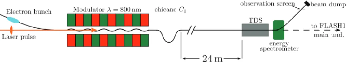
For these measurements, the hardware of the sFLASH seeding experiment has been used. It is installed in the FLASH1 electron beamline between the collimation section (dogleg) and the undulator system, compare Fig. 3. The electron bunches arriving from the collimation section of FLASH1 are modulated in an electromagnetic undulator (5 periods ofλu =20 cm,Kmax=10.8) by the 800-nm laser pulses arriving from the seeding laser system. After the modulator, chicaneC1 with variableR56is installed. For studies of LSC effects, we use a combination of a transverse- Proceedings of FEL2015, Daejeon, Korea TUA02
SASE FELs
ISBN 978-3-95450-134-2 289 Copyright©2015CC-BY-3.0andbytherespectiveauthors
315 m
5 MeV 150 MeV 1250 MeV
Bunch Compressors 450 MeV Accelerating Structures RF Stations
Lasers RF Gun
Soft X-ray Undulators sFLASH
FEL Experiments Photon Diagnostics
Beam Dump FLASH1 THz
Figure 2: Schematic layout of FLASH user facility. The electron bunch is laser-manipulated in a combination of modulator and chicane installed in thesFLASH experiment.
Figure 3: Hardware used for the measurements. The electron bunch arrives from the collimation section (dogleg) of the FLASH1 beamline and the 800-nm pulse from the laser system. In the modulator, the electron-light interaction imprints an energy modulation onto the bunch that is converted into a current modulation in the subsequent chicaneC1. After propagating along a 24-meter-long electron beamline, the electron bunches are characterized by the combination of a transverse-deflecting structure (TDS) and a dipole spectrometer.
deflecting structure (TDS) [4] and a dipole spectrometer installed about 13 m upstream of the FLASH1 SASE undula- tors. First, an arrival-time dependent vertical kick is applied in the TDS, an RF-structure operated at 2856 MHz. After introducing this longitudinal-to-vertical correlation, the lon- gitudinal phase-space distribution can be measured on the observation screen in the dispersive section downstream of the energy spectrometer.
For the measurements with FEL operation, the TDS and the energy spectrometer have to be disabled to allow for transport of the density modulated electron bunches to the FLASH1 main undulator. The energy of the XUV photon pulses is measured with the “gas-monitor detector” (GMD) [13], a gas-filled volume in the XUV photon beamline lead- ing to the FLASH1 experimental hall. In the GMD, the XUV photons ionize gas atoms and the ion and electron cur- rents indicate the FEL pulse energy. Additionally, spectra of XUV photon pulses were measured with a high-resolution spectrometer.
OVERVIEW OF MEASUREMENTS
The experiment was designed to meet two objectives: (i) investigation of the LSC-driven amplification mechanism and (ii) study of the impact of the LSC-amplified initial energy modulation on the FEL process in the FLASH1 SASE undulator.
Characterization of Amplification Process
To study the LSC-driven evolution of the electron bunches, we used electron bunches with an energy of 700 MeV, a
peak current of 0.3 kA, and an rms bunch duration of 0.3 ps.
After generating an energy modulation by interaction with 800-nm, approx. 60-fs (full-width half maximum, FWHM) laser pulses in the modulator, a current modulation is gener- ated in a chicane installed at the exit of the modulator. The manipulated electron bunches are then transported along a 24-m-long electron beamline. There, LSC forces drive the longitudinal expansion of high-current regions of the electron bunch. This process entails the accumulation of an energy modulation amplitude at the expense of the current modulation. At the end of this beamline, the longitudinal phase-space distributions of the seeded electron bunches have been characterized using the TDS in combination with a dipole energy spectrometer. From these measured longi- tudinal phase-space distributions, the slice energy spread has been extracted. This analysis has been carried out for a set of energies of the modulating laser pulses as well as for different longitudinal dispersions R56of the chicane used to generate the current modulation. The initial parameters have been deduced by applying a fitting procedure based on an LSC model simulated with the codeQField [14].
Suppression of FEL Lasing
In the second part of the experiment, the electron bunches were re-compressed to enable the SASE FEL process in the FLASH1 SASE undulator atλ = 13.1 nm. Here, the initial current modulation was generated using 0.2-ps-long (FWHM) laser pulses while the relative temporal jitter be- tween the laser pulses and the electron bunches was 58 fs rms [15]. With this ratio of the temporal jitter to the laser TUA02 Proceedings of FEL2015, Daejeon, Korea
ISBN 978-3-95450-134-2 290
Copyright©2015CC-BY-3.0andbytherespectiveauthors
SASE FELs
20 40 60 80 100 50
100 150
shot id
photon pulse energy [µJ]
Figure 4: Suppression of FEL lasing for moderate initial laser modulation. The photon pulse energies emitted by the electron bunches have been measured with the GMD detec- tor. Samples obtained with the modulating laser switched on are marked withred crosses.
pulse duration, the initial modulation is supposed to be well- reproducible [16]. As the manipulated electron bunches propagate to the FLASH1 SASE undulator, the energy mod- ulation amplitude grows. This degradation of the electron bunch parameters results in a reduction of the XUV pho- ton pulse energy, as shown in Fig. 4. Using the GMD to diagnose photon pulse energies, we studied this suppression of FEL lasing for different laser pulse energies and elec- tron beamline configurations. In particular, a significantly stronger suppression effect has been observed in a configura- tion with two chicanes. Moreover, measurements have been performed with a high-resolution spectrometer installed at the PG beamline in the FLASH1 user hall [17, 18] for var- ious settings of laser-generated initial energy modulation amplitude and longitudinal dispersionR56of the chicane.
SUMMARY AND OUTLOOK
We reported on measurements of a laser-seeded longitu- dinal space-charge oscillation. The laser-induced current modulation initiates a growth of the energy modulation am- plitude, which has been used to study suppression of FEL lasing. These measurements have been performed for dif- ferent laser and electron beamline configurations. A more detailed data analysis will be presented in [19].
Potential applications of these seeded LSC effects include the reduction of slice energy spread in HGHG-seeded FELs [20–22] and the selective suppression of FEL lasing [19].
ACKNOWLEDGEMENTS
We thank DESY and the FLASH team for the opportu- nity to perform our experiment. Supported by Federal Min- istry of Education and Research of Germany under contract No. 05K10PE1, 05K10PE3, 05K13GU4, 05K13PE3, and the German Research Foundation program graduate school 1355.
REFERENCES
[1] E.A. Schneidmiller and M.V. Yurkov,Using the longitudinal space charge instability for generation of vacuum ultraviolet and x-ray radiation, Phys. Rev. ST Accel. Beams 13, 110701 (2010).
[2] H. Loos, et al.,Observation of coherent optical transition radiation in the LCLS linac, Proc. 30th Intl. Free-Electron Laser Conf., Gyeongju, Korea, 2008, 485–489.
[3] S. Wesch, et al.,Observation of coherent optical transition radiation and evidence for microbunching in magnetic chi- canes, Proc. 31st Intl. Free-Electron Laser Conf., Liverpool, UK, 2009, 619–622.
[4] C. Behrens, et al.,Electron beam profile imaging in the pres- ence of coherent optical radiation effects, Phys. Rev. ST Accel.
Beams 15, 062801 (2012).
[5] S. Matsubara, et al.,Improvement of screen monitor with suppression of coherent-OTR effect for SACLA, Proc. of 1st Intl. Beam Instrumentation Conf., Tsukuba, Japan, 2012, 34–
37.
[6] A. Marinelli, et al.,Generation of Coherent Broadband Pho- ton Pulses with a Cascaded Longitudinal Space-Charge Am- plifier, Phys. Rev. Lett. 110, 264802 (2013).
[7] S. Seletskiy, et al.,Seeding, Controlling, and Benefiting from the Microbunching Instability, Phys. Rev. Lett. 111, 034803 (2013).
[8] D. Ratner, et al.,Time-resolved imaging of the microbunching instability and energy spread at the Linac Coherent Light Source, Phys. Rev. ST Accel. Beams 18, 030704 (2015).
[9] K. Honkavaara, et al.,Status of the Soft X-Ray FEL User Facility FLASH, These Proceedings: Proc. 37th Intl. Free- Electron Laser Conf., Daejeon, 2015, MOP014.
[10] C. Lechner, et al., Demonstration of SASE Suppression Through a Seeded Microbunching Instability, Proc. 36th Intl.
Free-Electron Laser Conf., Basel, 2014, 177–180.
[11] J. Bödewadt and C. Lechner,Results and perspectives on the FEL seeding activities at FLASH, Proc. 35th Intl. Free- Electron Laser Conf., New York, NY, USA, 2013, 491–495.
[12] M. Scholz, B. Faatz, and Siegfried Schreiber,First Simulta- neous Operation of Two SASE Beamlines in FLASH, These Proceedings: Proc. 37th Intl. Free-Electron Laser Conf., Dae- jeon, 2015, TUA04.
[13] K. Tiedtke, et al.,Gas detectors for x-ray lasers, J. Appl. Phys.
103, 094511 (2008).
[14] M. Dohlus, Ch. Henning,Periodic Poisson Solver for Particle Tracking, submitted (2015); preprint available as (i) DESY- 15-071 or (ii)http://arxiv.org/, code 1505.01330.
[15] C. Lechner, et al.,Measurements on the Timing Stability at the FLASH1 Seeding Experiment, Proc. 36th Intl. Free-Electron Laser Conf., Basel, 2014, 913 – 916.
[16] C. Lechner,Temporal Control of Laser-Electron Interaction at High-Gain Free-Electron Lasers, PhD thesis, University of Hamburg (2015).
[17] N. Gerasimova, S. Dziarzhytski, and J. Feldhaus, The monochromator beamline at FLASH: performance, capa- bilities and upgrade plans, J. Mod. Opt. 58, 1480 (2011).
Proceedings of FEL2015, Daejeon, Korea TUA02
SASE FELs
ISBN 978-3-95450-134-2 291 Copyright©2015CC-BY-3.0andbytherespectiveauthors
[18] M. Martins, et al.,Monochromator beamline for FLASH, Rev.
Sci. Instrum. 77, 115108 (2006).
[19] C. Lechner, et al.,in preparation
[20] K. Hacker,A Concept for Seeding 4-40 nm FEL Radiation at FLASH2, TESLA-FEL 2013-01 (2013).
[21] E. Hemsing, et al.,Correlated Energy-Spread Removal with Space Charge for High-Harmonic Generation, Phys. Rev.
Lett. 113, 134802 (2014).
[22] K. Hacker, et al.,Measurements and Simulations of Seeded Electron Microbunches with Collective Effects, These Pro- ceedings: Proc. 37th Intl. Free-Electron Laser Conf., Daejeon, 2015, WEP031.
TUA02 Proceedings of FEL2015, Daejeon, Korea
ISBN 978-3-95450-134-2 292
Copyright©2015CC-BY-3.0andbytherespectiveauthors
SASE FELs
![Figure 1: Schematic layout of a two-stage longitudinal space- space-charge amplifier (LSCA) configuration [1].](https://thumb-eu.123doks.com/thumbv2/1library_info/3773623.1512905/1.889.95.429.835.940/figure-schematic-layout-stage-longitudinal-charge-amplifier-configuration.webp)