MEASUREMENTS OF THE TIMING STABILITY AT THE FLASH1 SEEDING EXPERIMENT
∗C. Lechner
†, A. Azima, M. Drescher, L. L. Lazzarino, Th. Maltezopoulos, V. Miltchev, T. Plath, J. Rönsch-Schulenburg, J. Rossbach, M. Wieland, University of Hamburg, Hamburg, Germany
K. E. Hacker, S. Khan, R. Molo, DELTA, TU Dortmund University, Dortmund, Germany S. Ackermann, J. Bödewadt, H. Dachraoui, N. Ekanayake, B. Faatz, M. Felber, K. Honkavaara,
T. Laarmann, J. Müller, H. Schlarb, S. Schreiber, S. Schulz, DESY, Hamburg, Germany P. Salen, P. van der Meulen, FYSIKUM, AlbaNova, Stockholm, Sweden
G. Angelova Hamberg, Uppsala University, Uppsala, Sweden
Abstract
For seeding of a free-electron laser, the spatial and tempo- ral overlap of the seed laser pulse and the electron bunch in the modulator is critical. To establish the temporal overlap, the time difference between pulses from the seed laser and spontaneous undulator radiation is reduced to a few pico- seconds with a combination of a photomultiplier tube and a streak camera. Finally, for the precise overlap the impact of the seed laser pulses on the electron bunches is observed.
In this contribution, we describe the current experimental setup, discuss the techniques applied to establish the tempo- ral overlap and analyze its stability.
INTRODUCTION
For the operation of an externally seeded free-electron laser (FEL), relative beam-beam jitter between the electron bunch and the laser pulse initiating the FEL gain process is only acceptable to a certain extent. Inhomogeneities in the electron beam slice parameters will directly translate into fluctuating performance of the seeded FEL. The duration of the region of the bunch with suitable electron beam pa- rameters, such as slice energy spread, beam current, and emittance, is limited, which defines the timing jitter budget.
Large jitter will naturally result in poor overlap quality. For instance, a major limitation of the studies of direct seeding with an high-harmonic generation (HHG) source at FLASH was the quality of the temporal overlap [1, 2].
EXPERIMENTAL LAYOUT Electron Beamline
The seeding experiment is installed at the FLASH1 beam- line of FLASH [3], the free-electron laser user facility in Hamburg, delivering high-brilliance SASE FEL radiation in the extreme ultra-violet (XUV) and soft x-ray range wave- length ranges. The superconducting linear accelerator of the FLASH facility generates trains of high-brightness electron bunches at a maximum energy of 1.25 GeV. These bunch trains, accelerated at 10 Hz repetition rate, consist of up
∗Work supported by Federal Ministry of Education and Research of Ger- many under contract No. 05K10PE1, 05K10PE3, 05K13GU4, and 05K13PE3 and the German Research Foundation programme graduate school 1355.
†christoph.lechner@desy.de
to 800 electron bunches at an intra-train repetition rate of 1 MHz.
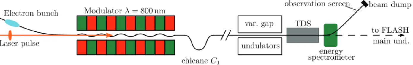
The seeding experiment is installed between the collima- tion section of FLASH1 and the FLASH1 main undulator system. The electron beamline, shown schematically in Fig. 1, can be divided into three parts: (i) the modulator section, (ii) the variable-gap undulator system, and (iii) the photon extraction and diagnostics section. Of these, however, only the modulator section was used for the measurements presented in this paper. It comprises two electromagnetic undulators (5 periods of 20 cm, maximum K value 10.8) that originally had been installed for a longitudinal elec- tron bunch diagnostics experiment [4]. At the exit of each electromagnetic undulator, a magnetic chicane is installed.
Downstream of the seeding experiment, a combination of a transverse-deflecting structure (TDS) and a dipole energy spectrometer is installed. First, an arrival-time-dependent transverse kick is applied in the TDS, an RF structure oper- ated at 2856 MHz. After this conversion of longitudinal to spatial position, the contents of the longitudinal phase space of the electron bunch can be measured on the observation screen in the dispersive section downstream of the energy spectrometer.
Laser System
The laser system used for seeding experiments at FLASH1 was originally installed for direct-HHG seeding experiments at FLASH and consists of a 108.3 MHz Ti:sapphire oscilla- tor used as seed in a classical chirped pulse amplification (CPA) scheme with 35 mJ maximum pulse energy at 35 fs FWHM minimal pulse duration. As described in the follow- ing section, the oscillator is electronically synchronized to a reference signal derived from an optical reference. The amplifier is pumped by a frequency-doubled Nd:YAG laser operating at 10 Hz allowing to seed one electron bunch per train [5].
For high-gain harmonic generation (HGHG) seeding at short wavelengths, a conversion of the λ = 800 nm laser pulses to UV wavelengths is required. For this, an in-vacuum arrangement of two non-linear optical crystals in the accel- erator tunnel is employed: While the first one converts the laser light into its second harmonic, the second one emits its third harmonic at 267 nm when overlapping the 800 nm and 400 nm pulses [6].
Proceedings of FEL2014, Basel, Switzerland THP076
FEL Technology and Hardware: Electron Diagnostics, Timing, Synchronization and Controls
ISBN 978-3-95450-133-5 913 Copyright©2014CC-BY-3.0andbytherespectiveauthors
Figure 1: Layout of the hardware used in these measurements. The electron bunches arrive from the energy collimator of FLASH1, the seed laser pulses are injected into the accelerator vacuum upstream of the last dipole of the energy collimator.
After modulation, the electron bunches are density-modulated in chicaneC1. Finally, the longitudinal phase space of the electron bunch is analyzed by the combination of a TDS and an energy spectrometer.
Synchronization System
For pump-probe experiments to benefit from femtosecond XUV pulses delivered by FELs, synchronization of laser systems and the electron bunch timing on the same time scale is essential. The synchronization system at FLASH is implemented with length-stabilized optical fibers dis- tributing trains of laser pulses with a repetition rate of 216.667 MHz [7]. These trains of optical pulses can be directly applied in electron beam diagnostics like bunch ar- rival monitors (BAMs) [8] or used for the synchronization of optical lasers using balanced optical cross-correlators (OXCs).
MEASUREMENT OF THE BEAM-BEAM JITTER
Establishing Laser-electron Overlap
For the measurements, we used mildly compressed elec- tron bunches with a peak current of 0.3 kA and an rms bunch duration of about 0.3 ps at an energy of 700 MeV. The elec- tron bunches and the laser pulses from the seeding laser are brought into spatial and temporal overlap in the modulator.
To establish the spatial overlap, OTR screen stations close to the entrance and the exit of the modulator are used to image the spatial profiles of both the electron beam and the seed laser beam.
To establish the temporal overlap, the spontaneous undu- lator radiation emitted by the electron bunches as well as the seed laser pulses are extracted from the electron beamline.
The light is sent to a fast photomultiplier tube to reduce the temporal offset of both signals to a few hundred picoseconds.
Next, the longitudinal phase space of the uncompressed elec- tron bunch is measured by the above described TDS and the laser timing is scanned electronically in sub-picosecond steps. The laser-induced modulation can then be directly observed on the TDS once the overlap is established. The camera images of the observation screen in the dispersive section were acquired using the FLASH data acquisition (DAQ) system. For this measurement, the variable-gap un- dulators were open and chicaneC1after the modulator was set toR56=295μm.
For time calibration of the longitudinal phase space measurement, we determined the centroid position of the
streaked electron bunch for a set of phases of the 2856 MHz RF driving the TDS. From this data, the time calibration was found to be(−4.58±0.21)fs/pixel.
Data Analysis
The acquired images are analyzed using standard image processing techniques: After subtracting of a background image, which has been recorded without electron beam, a region of interest (ROI) is determined. As the contour of the longitudinal phase space cannot be predicted, the ROI is determined by an image analysis algorithm. As the actual image of the streaked electron bunch defines the ROI for further analysis, the impact of fluctuations of the RF driving the TDS is greatly reduced.
A series of 200 images was used for this analysis. From the part of the image selected by the ROI, the slice energy spread is determined. The local maximum of the slice energy spread marks the center of the laser-electron interaction.
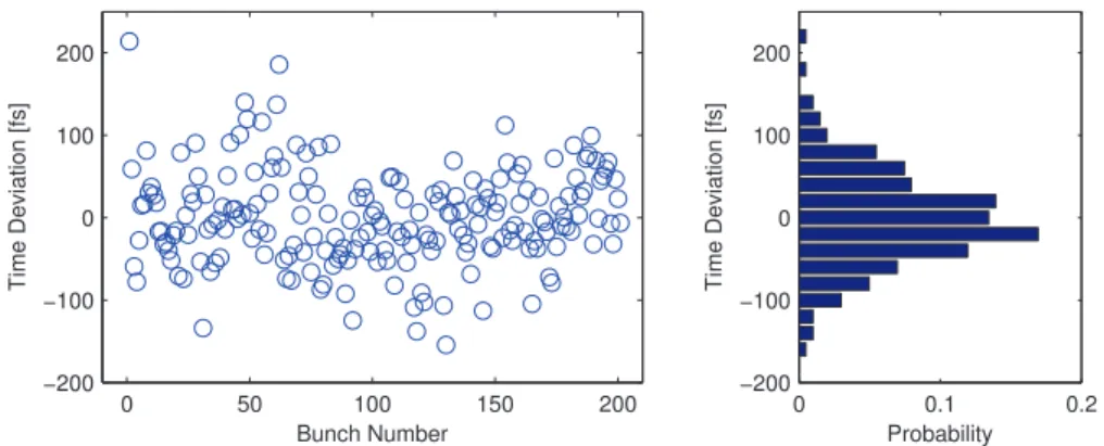
Figure 2 shows the arrival time information extracted from the analyzed TDS images; the corresponding histogram is in the right panel of this figure. From this data set, the relative beam-beam jitter is determined to be(57.8±5.0)fs.
For the error analysis, the effects introduced by the image analysis procedure, the uncertainty determining the slice with maximum slice energy spread, and the uncertainty of the time calibration of the TDS have been taken into account.
Discussion
The contributions to the total beam-beam jitter that can be measured independently are (i) jitter contribution of laser amplifier in the seeding laser system, (ii) electron beam jitter measured on the bunch arrival monitor (BAM), (iii) jitter of the optical synchronization system (however, negligible with
∼1 fs rms [9]), and (iv) contributions of the synchronization of the laser oscillator.
Using the bunch arrival monitor (BAM) downstream of the second bunch compressor chicane of the FLASH linac, the arrival time jitter of the electron bunches has been mea- sured. In the time interval under consideration, the rms arrival time jitter was 31 fs with the typical uncertainty for the electron bunch parameters being 13 fs. This measure- ment was performed in single-bunch operation after the upgrade of the FLASH low-level RF (LLRF) control sys- THP076 Proceedings of FEL2014, Basel, Switzerland
ISBN 978-3-95450-133-5 914
Copyright©2014CC-BY-3.0andbytherespectiveauthors
FEL Technology and Hardware: Electron Diagnostics, Timing, Synchronization and Controls
0 50 100 150 200
−200
−100 0 100 200
Bunch Number
Time Deviation [fs]
0 0.1 0.2
−200
−100 0 100 200
Probability
Time Deviation [fs]
Figure 2: Timing of the laser signatures for a series of 200 images of the longitudinal phase space. In the right panel, the corresponding histogram is shown.
Table 1: Compilation of the Independently Measured rms we obtain(48±10)fs. In this beamtime, the typical in-loop measured jitter of the RF-synchronization of the oscillator of the seeding laser system was 55 fs, which is somewhat overestimated due to the noise floor in the phase noise mea- surement.
rms timing jitter [fs]
beam-beam jitter (on TDS) 57.8±5.0 (i) beam arrival time (on BAM) 31±13
(ii) laser amplifier 10±1
(iii) synchronization system ∼1
tem to a MicroTCA.4-based solution [10]. The typical jitter introduced by the amplifier of the seeding laser system is (10±1)fs.
Subtracting contributions (i) – (iii) from the total beam- beam jitter extracted from the TDS images, we obtain (48 ± 10)fs. This value includes the jitter of the RF- synchronization of the oscillator of the seeding laser system, for which the typical in-loop measured value in this beam- time was 55 fs. We note that due to the noise floor in the phase noise measurement, which originates from the pho- todetector, the result of this in-loop measurement of the timing jitter is somewhat overestimated. The measured tim- ing jitter values are compiled in Table 1.
Assuming a desired minimum hit rate ofp=0.9, a beam- beam jitter of 60 fs rms would require the homogeneous region in the electron bunch to be at least 198 fs long. Prac- tical minimum durations would be longer as we did not consider the finite duration of the seed pulse or budget for small temporal drifts.
Measurements at Other Facilities
A similar measurement of the relative beam-beam jitter was performed at the seeded FEL user facility FERMI@Elettra [11, 12]. There, a linearly chirped elec- tron bunch is used to extract the jitter from electron energy
spectra measured at the beam dump. The laser-electron inter- action in the modulator changes the energy of the electrons in the modulated region, corresponding to a relocation of charge density in the energy distribution. Measured energy distributions are compared with those of a reference bunch, determining the energy of the electrons before modulation.
In a linearly chirped electron bunch, the beam energy at which this current reduction is observed can be related to a longitudinal position. Time calibration was found to be (0.22±0.02)pixel/fs by deliberately changing the laser tim- ing by ±100 fs about the working point. At FERMI, the analysis of 200 consecutive modulated electron bunches resulted in an rms timing jitter of 68 fs [11].
SUMMARY AND OUTLOOK
In this paper, we show measured values for the relative beam-beam jitter in the FLASH1 seeding experiment that have been obtained from an analysis of the laser-electron interaction that will also be used in seeding experiments.
Currently, the jitter is dominated by the RF-synchronization of the laser oscillator of the seeding laser system. An all- optical synchronization of this laser oscillator with a sub- 10 fs (rms) timing jitter to the optical reference has already been tested. An upgrade of the laser synchronization to this solution based on a balanced optical cross-correlator (OXC) is expected for this year.
ACKNOWLEDGEMENTS
We thank DESY and the FLASH team for the opportunity to perform our experiment. We thank M. K. Czwalinna for useful discussions. Supported by Federal Ministry of Education and Research of Germany under contract No.
05K10PE1, 05K10PE3, 05K13GU4, and 05K13PE3 and the German Research Foundation programme graduate school 1355.
REFERENCES
[1] S. Ackermann, et al.,Generation of Coherent 19- and 38-nm Radiation at a Free-Electron Laser Directly Seeded at 38 nm, Jitter Values. After subtraction of the contributions (i) – (iii),
Proceedings of FEL2014, Basel, Switzerland THP076
FEL Technology and Hardware: Electron Diagnostics, Timing, Synchronization and Controls
ISBN 978-3-95450-133-5 915 Copyright©2014CC-BY-3.0andbytherespectiveauthors
Phys. Rev. Lett. 111, 114801 (2013).
[2] J. Bödewadt and C. Lechner,Results and perspectives on the FEL seeding activities at FLASH, Proc. 35th Int. Free- Electron Laser Conf., New York, NY, USA, 2013, 491–495.
[3] K. Honkavaara, et al.,FLASH: First Soft X-ray FEL Oper- ating Two Undulator Beamlines Simultaneously, These Pro- ceedings: Proc. 36th Int. Free-Electron Laser Conf., Basel, 2014, WEB05.
[4] G. Angelova, et al., Observation of two-dimensional longitudinal-transverse correlations in an electron beam by laser-electron interactions, Phys. Rev. ST Accel. Beams 11, 070702 (2008).
[5] Th. Maltezopoulos, et al.,A high-harmonic generation source for seeding a free-electron laser at 38 nm, Appl. Phys. B, 115, 45–54 (2014).
[6] K. Hacker et al.,Progress towards echo-seeding in the FLASH ORS section, TESLA-FEL 2011-06 (2011).
[7] S. Schulz et al.,Past, present and future aspects of laser-based synchronization at FLASH, Proc. 2nd Int. Beam Instrumenta- tion Conf., Oxford, UK, 2013, 753–756.
[8] M.K. Bock, et al.,Benchmarking the performance of the present bunch arrival time monitors at FLASH, Proc. 10th Eu- ropean Workshop on Beam Diagnostics and Instrumentation for Particle Accelerators (DIPAC2011), Hamburg, Germany, 2011, 365–367.
[9] S. Schulz, et al.,Femtosecond-precision synchronization of the pump-probe optical laser for user experiments at FLASH, Proc. SPIE Vol. 8778 (Advances in X-ray Free-Electron Lasers II: Instrumentation), Prague, Czech Republic, 2013, 87780R.
[10] C. Schmidt, et al.,Performance of the MicroTCA.4 based LLRF system at FLASH, WEPME067, Proc. 5th Int. Particle Accelerator Conf., Dresden, Germany, 2014, 2433–2435.
[11] E. Allaria, et al.,Energy slicing analysis for time-resolved measurement of electron-beam properties, Phys. Rev. ST Accel. Beams 17, 010704 (2014).
[12] E. Allaria, et al.,Measurement of electron-beam and seed laser properties using an energy chirped electron beam, Proc.
35th Int. Free-Electron Laser Conf., New York, NY, USA, 2013, 24–26.
THP076 Proceedings of FEL2014, Basel, Switzerland
ISBN 978-3-95450-133-5 916
Copyright©2014CC-BY-3.0andbytherespectiveauthors
FEL Technology and Hardware: Electron Diagnostics, Timing, Synchronization and Controls