• Keine Ergebnisse gefunden

BEAM DYNAMICS ISSUES IN THE FCC ∗

N/A
N/A
Protected

Academic year: 2021

Aktie "BEAM DYNAMICS ISSUES IN THE FCC ∗ "

Copied!
6
0
0

Wird geladen.... (Jetzt Volltext ansehen)

Volltext

(1)

BEAM DYNAMICS ISSUES IN THE FCC

W. Bartmann, M. Benedikt, M.I. Besana, R. Bruce, O. Brüning, X. Buffat, F. Burkart, H. Burkhardt, S. Calatroni, F. Cerutti, S. Fartoukh, M. Fiascaris, C. Garion, B. Goddard, W. Höfle, B. Holzer, J.M. Jowett, R. Kersevan, R. Martin, L. Mether, A. Milanese, T. Pieloni, S. Redaelli, G. Rumolo,

B. Salvant, M. Schaumann, D. Schulte, E. Shaposhnikova, L.S. Stoel, C. Tambasco, R. Tomas, D. Tommasini, F. Zimmermann , CERN, Switzerland; G. Guillermo, CINVESTAV Merida, Mexico;

V. Kornilov, GSI Darmstadt, Germany; O. Boine-Frankenheim, U. Niedermayer, TU Darmstadt, Germany; T. Mitsuhashi, K. Ohmi, KEK, Japan; A. Chancé, B. Dalena, J. Payet, CEA, Saclay, France; P. Bambade, A. Faus-Golfe, J. Molson, LAL Orsay, France; J.-L. Biarrotte,

A. Lachaize, IPNO, France; J. Fox, G. Stupakov, SLAC, U.S.A.; J. Abelleira, E. Cruz, A. Seryi, JAI Oxford, U.K.; R. Appleby, U. Manchester, U.K.; M. Boscolo, F. Collamati, A. Drago, INFN-LNF, Italy; J. Barranco, EPFL, Switzerland; S. Khan, B. Riemann, TU Dortmund, Germany

Abstract

The international Future Circular Collider (FCC) study [1] is designing hadron, lepton and lepton-hadron colliders based on a new 100 km tunnel in the Geneva region. The main focus and ultimate goal of the study are high-luminosity proton-proton collisions at a centre-of-mass energy of 100 TeV, using 16 T Nb

3

Sn dipole magnets.

Specific FCC beam dynamics issues are related to the large circumference, the high brightness — made available by radiation damping —, the small geometric emittance, unprecedented collision energy and luminosity, the huge amount of energy stored in the beam, large synchrotron radiation power, plus the injection scenarios.

In addition to the FCC-hh proper, also a High-Energy LHC (HE-LHC) is being explored, using the FCC-hh magnet technology in the existing LHC tunnel, which can yield a centre-of-mass energy around 25 TeV.

MOTIVATION AND SCOPE

The Large Hadron Collider (LHC) [2] and its high- luminosity upgrade, the HL-LHC [3], have an exciting physics programme, which, covering the next 20 years, ex- tends through the mid 2030s. Counting from the start of its design study in 1983, more than 30 years were needed to design, build and commission the LHC. Therefore, the community must now urgently start preparing the next ac- celerator for the post-LHC period, as it has clearly been recognized by the 2013 Update of the European Strategy for Particle Physics [4].

A large circular hadron collider seems to be the only ap- proach to reach energy levels far beyond the range of the LHC, during the coming decades, so as to provide access to new particles with masses up to tens of TeV, through direct production, as well as to obtain tremendously increased pro- duction rates for phenomena in the sub-TeV mass range, with

∗This work was supported in parts by the European Commission under the Capacities 7th Framework Programme project EuCARD-2, grant agreement 312453, and the HORIZON 2020 project EuroCirCol, grant agreement 654305, as well as by the German BMBF.

†frank.zimmermann@cern.ch

the corresponding greatly improved precision and enhanced sensitivity to new physics.

The energy reach of a high-energy hadron collider is sim- ply proportional to the dipole magnetic field and to the bend- ing radius: E ∝ B × ρ. Assuming a dipole field of 16 T, achievable with Nb

3

Sn technology, the ring circumference must be about 100 km in order to reach the target value 100 TeV for the centre-of-mass energy.

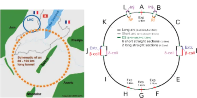
Figure 1 presents a schematic of the FCC tunnel along with a sketch of the hadron collider layout. Prior to FCC- hh installation, the new 100 km tunnel could host a high- luminosity circular e

+

e

collider (FCC-ee). Concurrent operation of hadron and lepton colliders is not foreseen how- ever. In addition, the FCC study considers aspects of pe collisions (FCC-he), as could be realized, e.g., by colliding the electron beam from an energy recovery linac (ERL) with one of the two FCC-hh hadron beams.

In the frame of the FCC study another future hadron col- lider is being studied, the so-called High Energy LHC (HE- LHC). The HE-LHC would be based on FCC-hh magnet technology, but be installed in the existing 26.7 km tunnel, which is presently housing the LHC.

Historically, investigations of an earlier version of the HE-LHC [5] gave birth to the FCC concept.

Figure 1: Left: Schematic of a 100 km tunnel for a Future Circular Collider (FCC) in the Lake Geneva basin. Right:

Layout of the FCC-hh ring. © 2016 CC-BY -3.0 and by the respecti v e authors

(2)

PARAMETERS AND OPTIONS

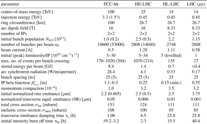
Table 1 compares key parameters of FCC-hh [6] and HE- LHC (preliminary) with those of LHC and HL-LHC. The FCC-hh design considers parameter sets for two phases of operation [7]: Phase 1 (baseline) aims at a peak luminosity of 5 × 10

34

cm

−2

s

−1

, and should deliver about 250 fb

−1

per year on average. In Phase 2 (ultimate) the peak luminosity is increased by almost a factor of six, to about 3 ×10

35

cm

2

s

1

, and the integrated luminosity by a factor of four to 1000 fb

1

per year.

The initial proton burn-off time can be computed as τ

bu

= N

b

n

b

/(L

0

σ

tot

n

IP

), where N

b

denotes the bunch population, n

b

the number of bunches per beam, and n

IP

the number of high-luminosity interaction points (IPs); n

IP

= 2 for all four colliders under consideration.

For both FCC-hh and HE-LHC there is an option of op- erating with a reduced bunch spacing of 5 ns, instead of the 25 ns spacing used at the LHC and HL-LHC. The total beam current would be the same, so that for 5 ns spacing the bunch charge is reduced by a factor of 5. To maintain the same luminosity (and the same beam-beam tune shift), the emittance also needs to be reduced by a factor 5, which appears possible — at least during the course of a physics fill — thanks to the strong radiation damping. The main advantage of 5 ns spacing is a factor five lower event pile up per bunch crossing in the particle-physics detectors. Possi- ble disadvantages include much reduced transverse Landau damping and potentially aggravated eletron-cloud effects.

LUMINOSITY EVOLUTION

The four hadron colliders operate in different regimes.

At the LHC, the intensity decreases due to burn off. For the HL-LHC it is held constant by levelling (e.g. dynamic change of β

x,y

during a physics fill [8]). In either of these two cases, the transverse emittances do not much evolve during a fill, since the weak radiation damping is roughly balanced by the effects of intrabeam scattering, gas scattering and beam-beam-related phenomena.

By contrast, for the FCC-hh the radiation damping is extremely strong, faster than the burn off. As a result the total beam-beam tune shift , ∆Q

bb

, and luminosity increase during the physics fill. From a certain moment onwards, the emittance shrinkage may need to be counteracted by controlled noise excitation, especially in Phase 1, in order for the beam-beam tune shift or detector pile-up not to exceed the empirical limits.

For the HE-LHC, the situation is again different. Here, the initial proton burn off is (two times) faster than the emittance shrinkage. In consequence, both the luminosity and the tune shift naturally decrease with time.

Figure 2 presents the evolution of instantaneous luminos- ity, integrated luminosity, bunch population, emittance, pile up and beam-beam tune shift for both phases of FCC-hh over 24 h of running. Here, we assume that the injected beam corresponds to the baseline parameters and a beam-beam tune shift of ∆Q

tot

≈ 0.01. In Phase 2 the emittances are

0 5 10 15 20

0 5 10 15 20 25

time [h]

34 -2 -1 luminosity [10 cm s ]

phase 1 phase 2

0 5 10 15 20

0 2 4 6 8

time [h]

integrated luminosity [fb ]-1

phase 1 phase 2

0 5 10 15 20

0 0.2 0.4 0.6 0.8

time [h]

phase 1 phase 2 bunch intensity [10 ]11

0 5 10 15 20

0 0.5 1 1.5 2

time [h]

phase 1

phase 2 normalized rms emittance [mm]

0 5 10 15 20

0 0.005 0.01 0.015 0.02 0.025 0.03

time [h]

total beam-beam tune shift

phase 1 phase 2

0 5 10 15 20

0 200 400 600 800

time [h]

event pile up per bunch crossing

phase 1 phase 2

Figure 2: Instantaneous luminosity, integrated luminosity, bunch population, emittance, total beam-beam tune shift, and event pile up as a function of time during 24 hours with 25 ns bunch spacing, for FCC-hh Phases 1 ( β

x,y

= 1.1 m,

∆Q

bb

= 0.01) and 2 ( β

x,y

= 0.3 m, ∆Q

bb

= 0.03) [7].

allowed to shrink, the tune shift increases during the fill, until the higher tune-shift limit of ∆Q

tot

= 0.03 is reached.

From this moment onwards the further emittance damping is counterbalanced by a controlled blow up keeping the beam brightness constant. Only the proton burn-off in collision and the natural, or — after reaching the beam-beam limit

— controlled emittance shrinkage due to radiation damping are taken into account. Other additional phenomena like gas scattering, Touschek effect, intrabeam scattering, and space charge are insignificant for the 50-TeV beams, in the scenarios considered.

Figure 3: Instantaneous luminosity, bunch population, emit- tance, and total beam-beam tune shift, as a function of time during 24 hours, for the HE-LHC with 25 ns bunch spac- ing [9]. Nominal β

x,y

= 0.25 m and ultimate β

x,y

= 0.15 m (∆Q

bb

= 0.025).

Similar pictures for the HE-LHC, in Fig. 3, reveal the difference in behavior: here the tune shift decreases while

© 2016 CC-BY -3.0 and by the respecti v e authors

(3)

Table 1: Key Parameters of LHC, HL-LHC, HE-LHC (tentative), and FCC-hh

parameter FCC-hh HE-LHC HL-LHC LHC (pp)

centre-of-mass energy [TeV] 100 25 14 14

injection energy [TeV] 3.3 (1.5?) 0.45 0.45 0.45

ring circumference [km] 100 26.7 26.7 26.7

arc dipole field [T] 16 16 8.33 8.33

number of IPs 2+2 2+2 2+2 2+2

initial bunch population N

b,0

[10

11

] 1.0 (0.2) 2.5 (0.5) 2.2 1.15

number of bunches per beam n

b

10600 (53000) 2808 (14040) 2748 2808

beam current [A] 0.5 1.29 1.11 0.58

initial (peak) luminosity/IP [10

34

cm

−1

s

−1

] 5–30 5–34 5 (levelled) 1 max. no. of events per bunch crossing 170–1020 (204) 1070 (214) 135 27

stored energy per beam [GJ] 8.4 1.4 0.7 ≈0.4

arc synchrotron radiation [W/m/aperture] 28.4 4.1 0.33 0.17

bunch spacing [ns] 25 (5) 25 (5) 25 25

IP beta function β

x,y

[m] 1.1–0.3 0.25 0.15 (min.) 0.55

momentum compaction [10

−4

] 1.0 3.2 3.5 3.2

initial normalized rms emittance [ µm] 2.2 (0.405) 2.5 (0.5) 2.5 3.75 normalized transverse equil. emittance (SR) [ µm] 0.05 0.006 0.01 0.001

total cross section σ

tot

[mbarn] 153 124 111 111

inelastic cross section σ

intel

[mbarn] 108 100 85 85

transverse emittance damping time τ

[h] 1.08 4.5 25.8 25.8

initial intensity burn off time τ

bu

[h] 19.2–3.2 2.3 15.5 40.4

protons are consumed. For HE-LHC, the integrated lumi- nosity barely improves when reducing β

x,y

below 0.25 m.

The evolution for 5 ns spacing would look the same as for 25 ns spacing, except that bunch population, transverse emittance and event pile up would all be a factor 5 lower.

SYNCHROTRON RADIATION

At the FCC-hh an unprecedentedly large synchrotron radi- ation power of about 2.3 MW per beam is emitted in the cold arcs. To efficiently absorb this synchrotron radiation a new beam screen, inserted inside the cold bore of the magnets, is proposed [10, 11]. As shown in Fig. 4, it features two slits with an integrated wedge such that most primary photons generated at 50 TeV beam energy are deflected upward and downward behind the beam screen, where pumping holes are placed, and very few photoelectrons are generated in- side the beam screen proper. In addition, the beam screen temperature will be raised, from 5–20 K at the LHC to 40–

60 K at the FCC-hh. The higher temperature improves the Carnot efficiency and, thereby, facilitates the removal of the synchrotron radiation heat load.

An unsolved issue is the correction of the dispersion gen- erated from the vertical crossing at one of the two high luminosity experiments. If this dispersion is corrected using vertical orbit bumps along the adjacent short arcs, here the synchrotron radiation fan can miss the beam screen slits.

Preliminary simulations show that this would generate only a limited increase of the average gas density around the ring;

it could still give rise to significant electron-cloud effects, especially at 5 ns bunch spacing.

29,6

26,4

Ø47 Ø44

2,9

Figure 4: FCC-hh beam-screen design with integrated

“folded” antechamber [10, 11].

As in electron storage rings, the eventual balance of the radiation damping by photon quantum fluctuations, in con- junction with the nonzero design dispersion, gives rise to a horizontal equilibrium emittance,

eq

, which can here be considered a lower bound on the available emittance range. Its value is given by

eq

≈ C

q

γ

2

θ

3hc

F, where θ

hc

denotes the bending angle per half cell (0.0165 rad for the LHC, 0.001 rad for the FCC-hh), F is a numerical factor of order 1 which depends on the optics and the filling fac- tor [12] (F ≈ 3.1 for a FODO cell with 90 degree phase advance and 80% dipole-magnet filling factor in the arcs),

© 2016 CC-BY -3.0 and by the respecti v e authors

(4)

and C

q

= 55/(32 √

3) ~ c/(m

p

c

2

) ≈ 2.09 × 10

16

m des- ignates the quantum constant for protons. For the hadron colliders which we consider in this paper (LHC, HE-LHC and FCC-hh) the equilibrium emittances from synchrotron radiation are one to three orders magnitude smaller than the initial emittances considered for use in operation (see Table 1). However, for FCC-hh Phase 2 with 5 ns spacing the final emittance at the end of a physics fill will reach this equilibrium emittance value: This type of operation will indeed be limited by the quantum fluctuations.

Synchrotron-light based emittance diagnostics has long been used at electron storage rings and has also proven an efficient non-invasive monitoring tool for the LHC.

The FCC and the HE-LHC will operate with a much smaller geometric emittance, and much higher energy. The FCC-hh will also have a larger bending radius than the LHC.

A comparison is given in Table 2, where the parameters for a modern light source (MAX-IV) are included for comparison.

The emittances of the various FCC-hh scenarios are much smaller than the horizontal emittance for any storage-ring based light source operating or under construction. For 5 ns spacing, the transverse emittance also becomes smaller than the lowest vertical emittances found in electron-storage rings. Indeed the FCC-hh will produce diffraction-limited light down to wavelengths of λ ∼ 4π ≤ 0.1–0.01 nm, thereby becoming a truly “ultimate storage ring”. The criti- cal photon energy in the 16 T dipoles, 4.3 keV, corresponds to a wavelength of 0.28 nm.

For the FCC-hh, at a location with large beta function, β ≈ 2 km, the rms beam size will be 200 µm. A synchrotron light monitor based on visible light (λ = 500 nm) from a standard arc bending magnet can be used over the entire energy range from 3 TeV to 50 TeV [13]. Similar to the existing diagnostics at the LHC, this will allow standard beam profile imaging, SR interferometry [14] for beam-size measurements, and coronograph techniques [15] for beam halo measurement.

In addition, at FCC-hh, for beam energies above 30 TeV, hard X-rays (10 keV) will also become available. In this energy range, an X-ray pinhole camera will be a convenient method for monitoring the beam profile and beam size [13].

Pinhole arrays are sometimes used to monitor beam size and divergence simultaneously, e.g. [16].

INJECTOR SCENARIOS

The baseline scheme is to inject at a beam energy of 3.3 TeV from the present LHC, with upgraded ramping (factor 5 higher speed [17]) and decommissioned interaction regions (IRs). The minimum FCC filling time then becomes 40 minutes (4 ramps). Another option, which could also provide an energy of 3.3 TeV, is a 100-km superferric booster in the FCC tunnel itself.

One alternative, with lower injection energy around 1.5 TeV, is based on a superconducting High Energy Booster (HEB) installed in the SPS tunnel. The filling time of 34 minutes (34 ramps) is only marginally lower than for the injection using the LHC. However, the HEB could greatly

facilitate operation, avoid superconducting transfer lines, and relax machine protection issues during the injection.

Main concerns related to the lower injection energy of 1.5 TeV are the much increased persistent current effects and reduced beam stability with regard to impedance.

Enhanced persistent-current field errors at 1.5 TeV imply a chromaticity swing of 800–1600 units, which could possibly be reduced either by optimizing the magnet design or by using smaller filaments in the superconducting wire.

Proposed machine studies in LHC [18] and RHIC [19]

aim at exploring the possibility of lowering the injection energy for these machines and accelerating a beam through the “b

3

minimum,” as proof-of-principle experiments.

OPTICS AND IR

The layout of the FCC-hh machine was illustrated in the right picture of Fig. 1. A full ring optics for FCC-hh is already available, including arcs, IR, injection region with RF section, betatron collimation, energy collimation, and extraction/dump line.

This optics can support β

values down to 0.3 m or even 0.05 m [20, 21]. It is compatible with the achromatic tele- scopic squeeze (ATS) scheme [22]. A β

of 5 cm is the limit determined by beam stay clear considerations [20]. This also turns out to be the minimum useful value with regard to integrated luminosity [21].

The interaction region design is scaled from the LHC/HL- LHC. The free length from the collision point to the first quadrupole is 45 m, i.e. about twice the length at the LHC, which also provides the space needed for forward spectrom- eter and compensator dipoles. The total length of the final quadrupole triplet exceeds 100 m.

The inside of the final quadrupoles needs to include a ≥15 mm tungsten shield against collision debris to guarantee a magnet lifetime of at least 5 years [23–25].

COLLECTIVE EFFECTS

The low revolution frequency of the FCC enhances the resistive-wall instability. The growth rate of the most af- fected lowest-frequency mode scales as [26]

1

τ ≈ − I

beam

√ ρ γQ

β

f

rev3/2

b

3

sgn(∆

β

)

p |∆

β

| (1) where ρ designates the resistivity of the inner side of the beam screen, Q

β

the betatron tune, ∆

β

the fractional part of the betatron tune (with values between −1/2 and 1/2), and b the vertical half gap. The FCC-hh half gap is 13 mm instead of 17 mm for the LHC. The betatron tune is about 2 times the LHC tune. The revolution frequency is 4 times lower. At the higher beam-screen temperature of 50 K (compared with 5–20 K at the LHC), the surface copper layer (at RRR ∼ 100 [27]) has about a 5 times higher resistivity ρ. The FCC-hh resistive-wall instability growth time at the LHC betatron tune of ∆

β

= 0.32 amounts to 47 turns at an injection energy of 1.5 TeV and 91 turns at 3.3 TeV [28]. The

© 2016 CC-BY -3.0 and by the respecti v e authors

(5)

Table 2: Emittances and a few other parameters for LHC, HE-LHC (tentative), and FCC-hh, compared with the corresponding values at a modern electron-beam light source (MAX-IV).

parameter FCC-hh Phase 1 (2) HE-LHC LHC (pp) MAX-IV

beam energy [TeV] 50 12.5 7 0.003

bunch spacing [ns] 25 5 25 5 25 10

initial bunch population N

b,0

[10

11

] 1.0 0.2 2.5 0.5 1.15 0.3

initial geometric rms emittance [pm] 41 8 188 38 500 200

final geometric rms emittance [pm] 19 (2) 4 (1) 98 20 500 200

wave length at diffraction limit [nm] 0.025–0.5 0.01–0.1 1.2–2.4 0.25–0.48 6.3 2.5

arc bending radius [km] 10.4 2.8 2.8 0.019

critical photon energy [keV] 4.3 0.25 0.044 3.1

corresponding growth rates can be damped by a (possibly distributed) multi-band feedback system [29]. The instability may be further weakened by coating the beam screen with HTS materials like Tl-1223 or YBCO [30]. The single- bunch threshold of the transverse mode coupling instability is about an order of magnitude higher than the nominal bunch charge.

The electron-cloud instability needs to be addressed for the two bunch spacings of 5 and 25 ns. At the shorter spacing, Landau damping of multi-bunch instabilities by octupole magnets in the arcs will be 5 times less effective. Combin- ing the FCC-hh beam-screen design featuring “antechamber”

slits with a beam-screen surface layer of low secondary emis- sion yield (obtained, e.g., by means of amorphous carbon coating or laser treatment [31]), may render the electron cloud harmless at any bunch spacing.

Achievable total head-on beam-beam tune shifts are taken to range from 0.01 (Phase 1) to 0.03 (Phase 2) as already demonstrated at the LHC without any noticeable effect on lifetime or emittance evolution.

COLLIMATION AND PROTECTION

A preliminary collimation system design has been devel- oped for the FCC-hh based on scaling arguments [32]. At present the betatron collimation section extends over a con- siderable length of 2.8 km. Future options include smaller gaps, use of advanced, higher-performance collimator mate- rials, deployment of bent crystals or electron lenses etc.

First simulations of collimation efficiency for the present system indicate a potential problem with losses of off-energy particles in the dispersion suppressors located downstream of the collimator insertions [33–35] and around the high- luminosity collision points. It is planned to add collimators at adequate locations in the dispersion suppressors, like those to be installed for the HL-LHC.

At top energy, the energy stored in the FCC-hh beams is about 20 times higher than for the LHC. Machine pro- tection is critical. Pertinent aspects include the survival of the collimators in standard operation, in presence of regular losses, and in case of the asynchronous firing of a beam dump kicker, and the injection process, where the number of bunches per shot will be more limited than for the LHC.

FCC HEAVY-ION PERFORMANCE

Like the LHC, the FCC-hh could provide collisions of nuclear beams. Table 3 summarizes the principal beam pa- rameters for Pb-Pb and p-Pb collisions [36, 37]. For heavy ions, the synchrotron radiation damping rates are about twice as fast as those of protons while the low-intensity equilib- rium emittance is very much smaller (and unlikely ever to be reached). In a typical fill, the luminosity first rises sharply and subsequently decays in a regime governed by the in- terplay among luminosity burn-off, intra-beam scattering (IBS) and radiation damping [36]. The peak Pb-Pb lumi- nosity at the FCC-hh is about 60 times higher than the de- sign value for the LHC ALICE experiment. As at the LHC, photon-photon and photo-nuclear interactions will generate secondary beams emerging from the interaction points with intensities proportional to luminosity. The power they carry will increase from several tens of watts at the LHC to sev- eral kW. Suitable absorbers will have to be included in the dispersion suppressor sections to intercept them and avoid magnet quenches.

Table 3: Selected Beam and Performance Parameters for the FCC-hh in Pb-Pb and p-Pb Modes [36, 37]

operation mode Pb-Pb p-Pb

beam energy [TeV] 4100 50

c.m. energy/nucl. √

s

NN

[TeV] 39.4 62.8

no. of bunches / beam 2072 2072

bunch population [10

8

] 2.0 164 transv. norm. emittance [µm] 1.5 3.75 IP beta function β

x,y

[m] 1.1 hor. IBS emit. growth time [h] 23.4 4 × 10

3

long. emit. rad. damping time [h] 0.24 0.5 init. luminosity [10

27

cm

−2

s

−1

] 24.5 2052 peak luminosity [10

27

cm

−2

s

−1

] 57.8 9918

CONCLUSIONS

Future hadron colliders like FCC-hh and HE-LHC will enter a new parameter regime, which implies novel chal- lenges as well as novel opportunities in beam dynamics, and calls for innovative technological approaches.

The rapidly growing global FCC collaboration is devel- oping a cost-effective design with optimized performance.

© 2016 CC-BY -3.0 and by the respecti v e authors

(6)

REFERENCES

[1] FCC web site http://cern.ch/fcc.

[2] O.S. Brüning et al., LHC Design Report, v.1: the LHC Main Ring,” CERN Yellow Report CERN-2004-003-V-1 (2004).

[3] G. Apollinari et al., “High-Luminosity Large Hadron Col- lider (HL-LHC): Preliminary Design Report,” CERN Yellow Report CERN-2015-005 (2015).

[4] European Strategy Session of Council, 30 May 2013, CERN- Council-S/106 (2013).

[5] E. Todesco and F. Zimmermann (eds.), “EuCARD-AccNet- EuroLumi Workshop: The High-Energy Large Hadron Col- lider,” CERN Yellow Report CERN-2011-003 (2011).

[6] D. Schulte et al., “Future Circular Collider Study Hadron Col- lider Parameters,” FCC-ACC-SPC-0001, EDMS no. 1342402 (2014)

[7] M. Benedikt, D. Schulte, F. Zimmermann, “Optimizing Inte- grated Luminosity of Future Hadron Colliders”, Phys. Rev. ST – Accel. Beams 18, 101002 (2015).

[8] A. Gorzawski et al., CERN-ACC-NOTE-2015-0043 (2015).

[9] M. Benedikt, S. Fartoukh, F. Zimmermann, HE-LHC WG meeting 20 May 2016

[10] R. Kersevan, “Beam Screen Design and Cooling, Vacuum Aspects, Synchrotron Radiation”, Review of the FCC-hh Injection Energy, CERN, 16 October 2015, http://indico.

cern.ch/event/449449.

[11] C. Garion, “FCC-hh beam screen studies and beam screen cooling scenarios,” FCC Week 2016, Rome.

[12] L.C. Teng, “Minimizing the Emittance in Designing the Lat- tice of an Electron Storage Ring,” Fermilab, TM-1269 (1984).

[13] T. Mitsuhashi et al., “Conceptual Design for SR Moni- tor iin the FCC Beam Emittanxe (Size) Diagnostic,” in Proc. IPAC’16, Busan, Korea (2016) pp. 133.

[14] G. Trad et al., “Performance of the Upgraded Synchrotron Radiation Diagnostics at the LHC,” in Proc. IPAC’16, Busan, Korea (2016) p. 306.

[15] T. Mitsuhashi et al., “Design of Coronagraph for the Obser- vation of Beam Halo at LHC,” in Proc. IBIC’15, Melbourne, Canada (2015), p. 288.

[16] W.B. Peatman, K. Holldack, “Diagnostic Frontend for BESSY II,” J. Synchrotron Rad. 5 (1998) 639.

[17] A. Milanese, B. Goddard, M. Solfaroli, “Faster ramp of LHC for use as an FCC High Energy hadron Booster,” CERN- ACC-2015-133 (2015).

[18] M. Solfaroli et al., “FCC Related MDs (MD on 225 GeV LHC Injection),” CERN Ext. LSWG Meeting, 18 January 2016.

[19] C. Montag, “Accelerating Protons through the b

3

Minimum in RHIC,” BNL intenal note, October 2015.

[20] R. Martin, “ β

Reach Studies,” FCC Week 2016, Rome.

[21] X. Buffat, D. Schulte, “Beam Parameter Evolution and Lumi- nosity Performance,” FCC Week 2016, Rome.

[22] S. Fartoukh, “Achromatic telescopic squeezing scheme and application to the LHC and its luminosity upgrade,”

Phys. Rev. ST Accel. Beams 16, 111002 (2013).

[23] M.I. Besana, F. Cerutti, “Collision Debris on the Triplet Quadrupoles,” FCC Week 2016, Rome.

[24] M.I. Besana et al., “Assessment and Mitigation of the Proton- Proton Collision Debris Impact on the FCC Triplet,” in Proc. IPAC’16, Busan, Korea (2016) pp.1410–1413.

[25] R. Martin et al., “Radiation Load Optimization in the Final Focus System of FCC-hh,” in Proc. IPAC’16, Busan, Korea (2016) pp.1462–1465.

[26] A. Chao, Physics of Collective Beam Instabilities in High Energy Accelerators, J. Wiley (1993).

[27] F. Caspers et al., “Surface Resistance Measurements of LHC Dipole Beam Screen Samples,” in Proc. of EPAC’00, Vienna, Austria (2000).

[28] O. Boine-Frankenheim, “FCC-hh Impedances and Instabili- ties,” FCC Week 2016, Rome.

[29] W. Höfle, “The LHC RF transverse system and perspectives for FCC-hh,” FCC Week 2016, Rome.

[30] O. Brüning et al., “High Energy LHC Document prepared for the European HEP strategy update,” CERN-ATS-2012-237 (2012);

W. Barletta et al., “Future hadron colliders: From physics perspectives to technology R&D,” NIM A 764 (2014) p. 352;

also see G. Stupakov, FCC Week 2015 Washington; S. Ca- latroni, “Status Report on HTS Coating Study,” FCC Week 2016 Rome.

[31] R. Valizadeh et al., “Low Secondary Electron Yield of Laser Treated Surfaces of Copper, Aluminium and Stainless Steel,”

in Proc. IPAC’16, Busan, Korea (2016) p. 1089.

[32] M. Fiascaris, “Collimation System Study Overview and Plans,” FCC Week 2016, Rome.

[33] M. Fiascaris and S. Redaelli, “Betatron Collimation Effi- ciency,” FCC Week 2016, Rome.

[34] J. Molson et al., “Simulation of the FCC-hh Collimation System,” FCC Week 2016, Rome.

[35] M. Fiascaris et al., “First design of a proton collimation sys- tem for 50 TeV FCC-hh”, in Proc. IPAC’16, Busan, Korea (2016) p. 2423.

[36] M. Schaumann, “Potential performance for Pb-Pb, p-Pb, and p-p collisions in a future circular collider, Phys. Rev. ST Ac- cel. Beams 18, 091002 (2015).

[37] A. Dainese et al., “Heavy ions at the Future Circular Collider,”

contribution to forthcoming CERN Report on Physics at FCC- hh, http://arxiv.org/abs/1605.01389.

© 2016 CC-BY -3.0 and by the respecti v e authors

Abbildung

Figure 1 presents a schematic of the FCC tunnel along with a sketch of the hadron collider layout
Table 1 compares key parameters of FCC-hh [6] and HE- HE-LHC (preliminary) with those of HE-LHC and HL-HE-LHC
Table 1: Key Parameters of LHC, HL-LHC, HE-LHC (tentative), and FCC-hh
Table 2: Emittances and a few other parameters for LHC, HE-LHC (tentative), and FCC-hh, compared with the corresponding values at a modern electron-beam light source (MAX-IV).

Referenzen

ÄHNLICHE DOKUMENTE

The dynamics of investment and labour demand: Theoretical issues and an.. application to the Dutch

Die Erfindung lost das angegebene technische Problem durch Verwendung flussiger UV- hartbarer Farbmittel, die einen sehr dunnen Farbstof f f ilm bilden und dem Prinzip nach wie

The nature of telecommunications makes it d f i c u l t to analyze and assess the impact of individual services: one has to take into account economic,

FOR PROGNOSTIC A?ID RETROSPECTI'IE RESEAECH THIS IS ILLUSTRATED BY: -- THE LONG HISTORY OF COAL MINING IN VARIOUS CONDITIONS -- THE DIFFERENT ROLES OF THE COAL INDUSTRY IN

Investigation  into  the  determinants  of  the  profitability  of  microfinance 

However, the issue of perioperative fluid manage- ment is complicated, including such factors as the composition (colloid / crystalloid) of the fluid admi n - is tered, the amount

EPA’s regulations on greenhouse gas emissions from both mobile and stationary sources and on conventional and hazardous air pollutants emitted by electric power plants, cement

11 Peace Corps, Office of the Inspector General, Final Audit Report: Peace Corps Volunteer Safety and Security Program, IG-10-08-A, April 2010... considered unsafe, and