Inserat
Steinmüller
Anzeige 2
Waste Incineration
How to Optimize Recycling Rates Using Waste Incineration
Wilfried Frehmann and Till Lemme
1. Waste composition ...332
2. Slag/bottom ash treatment ...334
2.1. Slag/bottom ash washing...335
2.2. Conventional screening ...336
2.3. Optimized recycling ...336
3. Boiler and filter ash treatment ...336
3.1. Boiler ash separation ...336
3.2. Filter ash treatment ...336
4. HCl and gypsum generation ...338
4.1. HCl scrubber and HCl recovery ...338
4.2. SO2 scrubber and gypsum recovery ...338
4.3. Recovery rates for Cl and S ...339
5. Summary ...339
6. References ...340
The improvement of recycling and reuse of waste is becoming more and more important and it is generally preferred compared to waste incineration. In fact, the incineration of waste is often considered the last alternative when recycling of a certain waste fraction is technically not possible or there is simply no market for the corresponding fraction of the waste.
But instead of considering waste incineration as being contradictory to recycling, it may also be considered as an alternative way to achieve higher recycling rates. The main goal of waste to energy is the use of the chemical energy contained in the carbon and hydrogen, and transfer this into thermal energy. But all other elements contained in the waste will of course also be found in the various residue streams leaving the plant. For these residue streams there are possibilities for further treatment, enabling separation of certain elements, improvement of the quality of a residue stream to allow re-use on the market or even potential for the preparation of a new product.
Waste Incineration
Apart from increasing the pressure to reuse and recycle, either from the public, or simply due to rising market prices for certain elements, there are also other possible reasons: So far waste incineration is used widespread in industrial countries with clear guidelines for treatment and disposal of the residues such as slag/bottom ash or flue gas treatment residues. These proven ways for disposal of the residues may not be possible in many other countries or especially if solutions for archipelagic states are being considered. In addition the market prices for certain materials may be higher in such states, also justifying higher effort for treatment and separation of the residue streams from a waste incineration plant. And finally, if there are certain residues which cannot be reused or disposed off within the country itself, the amount shall be mini- mized as much as possible in order to reduce the costs for transport to a disposal facility.
This article describes the main process steps and the required process technology to optimize recycling rates for waste incineration plants. Most of it has been built and implemented in commercial scale facilities by Steinmüller Babcock Environment GmbH. Where a process has not been implemented on commercial scale, tests and studies have proven that, from a technological point of view, the successful implemen- tation is possible.
1. Waste composition
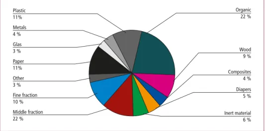
In order to evaluate the possibilities for optimized recycling rates, it is of course im- portant to understand the composition of the waste and in which output stream of the waste incineration plant the individual elements and chemical compounds can be found. A rather general view on the waste composition identifies the following groups of components and their share in typical household waste of Western Europe.
Organic 22 %
Paper
11% Composites
4 %
Inert material 6 % Glas
3 % Plastic 11%
Wood 9 % Metals
4 %
Other 3 % Fine fraction 10 %
Diapers 5 %
Middle fraction 22 %
Figure 1: Typical waste composition as input into waste incineration plants
Source: Dehoust, G.; Gebhard, P.; Gärtner, S.: Der Beitrag der thermischen Abfallbehandlung zu Klimaschutz, Luftreinhaltung und Ressourcenschonung. Institut für angewandte Ökologie, Darmstadt, 2002
Waste Incineration
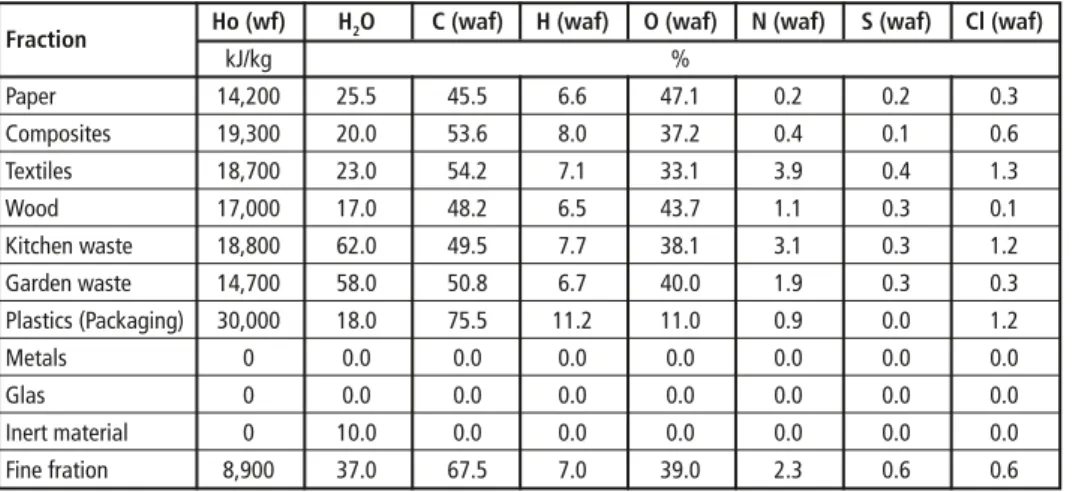
Figure 1 shows that there are groups of components which contain combustible matter, while others do not contain any combustible matter. For the combustion behavior of the waste it is of course interesting how the combustible matter contained in the waste is composed. This is exemplary shown in Table 1 for the main fractions.
Table 1: Heating value and elementary analysis of different waste fractions
Fraction Ho (wf) H2O C (waf) H (waf) O (waf) N (waf) S (waf) Cl (waf)
kJ/kg %
Paper 14,200 25.5 45.5 6.6 47.1 0.2 0.2 0.3
Composites 19,300 20.0 53.6 8.0 37.2 0.4 0.1 0.6
Textiles 18,700 23.0 54.2 7.1 33.1 3.9 0.4 1.3
Wood 17,000 17.0 48.2 6.5 43.7 1.1 0.3 0.1
Kitchen waste 18,800 62.0 49.5 7.7 38.1 3.1 0.3 1.2
Garden waste 14,700 58.0 50.8 6.7 40.0 1.9 0.3 0.3
Plastics (Packaging) 30,000 18.0 75.5 11.2 11.0 0.9 0.0 1.2
Metals 0 0.0 0.0 0.0 0.0 0.0 0.0 0.0
Glas 0 0.0 0.0 0.0 0.0 0.0 0.0 0.0
Inert material 0 10.0 0.0 0.0 0.0 0.0 0.0 0.0
Fine fration 8,900 37.0 67.5 7.0 39.0 2.3 0.6 0.6
wf: water free; waf: water and ash free
Source: Kost, T.: Brennstofftechnische Charakterisierung von Abfällen. In: Schriftenreihe des Instituts für Abfallwirtschaft und Altlasten, Band 16. Dresden, 2001
The combustible matter will of course mainly be transferred into gaseous state and leave the plant in form of flue gas through the stack. Important for consideration of optimized recycling rates is the transfer of Sulfur and Chlorine into the various output streams.
While Sulfates can be found to a considerable amount in the slag/bottom ash, the major drain for Sulfur and Chlorine remains the flue gas. Thus a plant concept which allows recovery of these elements should be favored to increase the recycling rates of the waste incineration plant.
A major challenge when it comes to optimized recycling rates is the output of (heavy) metals. These elements and their compounds will either be transferred into the slag/bot- tom ash, or will be discharged with the fly ash via the fabric filter. The transfer rate either into the slag/bottom ash or into the fly ash is dependent on the evaporating temperature of the metals. Therefore the fly ash contains a much higher rate of those heavy metals with a low evaporating temperature.
Last but not least there will be a formation of PCDD/PCDF within the boiler system at a temperature window of 200 °C to 400 °C, especially in the presence of metallic dust particles which act as a catalyst. The PCDD/PCDF will be adsorbed by the injection of activated carbon or equivalent products and then they are collected in the dust precipitator – ESP or fabric filter – which is usually installed as a first step of the gas cleaning system.
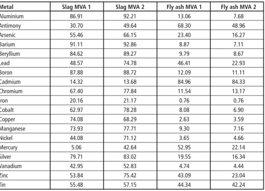
Table 2 shows the transfer coefficients for various metals, heavy metals and semi-metals into the slag/bottom ash and into the fly ash. The missing amount to fill up 100 percent is mainly recycled with the scrap metal fraction which is not included in this overview.
Waste Incineration
In addition there is a very small fraction leaving the plant in form of emissions through the stack and another small fraction will be recovered/discharged via the waste water treatment plant of the corresponding plants.
Considering the figures in Table 2, the amount of (semi-)metals remaining in the slag/
bottom ash and in the fly ash has a potential for recovery. Additional efforts regarding separation and recycling should be taken either because of an economic benefit or in order to reduce the environmental impact.
Table 2: Transfer coefficients for metals into different output streams of two waste incineration plants
Metal Slag MVA 1 Slag MVA 2 Fly ash MVA 1 Fly ash MVA 2
Aluminium 86.91 92.21 13.06 7.68
Antimony 30.70 49.64 68.30 48.96
Arsenic 55.46 66.15 23.40 16.27
Barium 91.11 92.86 8.87 7.11
Beryllium 84.62 89.27 9.79 8.67
Lead 48.57 74.78 46.41 22.93
Boron 87.88 88.72 12.09 11.11
Cadmium 14.32 13.68 84.96 84.33
Chromium 67.40 77.84 11.54 13.17
Iron 20.16 21.17 0.76 0.76
Cobalt 62.97 78.28 8.08 6.90
Copper 74.08 68.29 2.63 3.59
Manganese 73.93 77.71 9.30 7.16
Nickel 44.08 71.12 3.65 4.66
Mercury 5.06 42.64 52.95 22.14
Silver 79.71 83.02 19.55 16.34
Vanadium 42.95 52.83 4.74 4.44
Zinc 53.84 75.42 43.09 23.04
Tin 55.48 57.15 44.34 42.24
Source: Löschau, M.: Input-Output-Analyse als Methode der stofflichen Bilanzierung komplexer Entsorgungssysteme. Technische Universität Berlin, 2006
2. Slag/bottom ash treatment
Conventional slag treatment allows recycling of > 90 percent of Fe and Non-FE metals contained in the slag. Still there is considerable potential for improvement of the recycling rate as well as improvement for the slag properties in order to broaden the possibilities to re-use the slag as such.
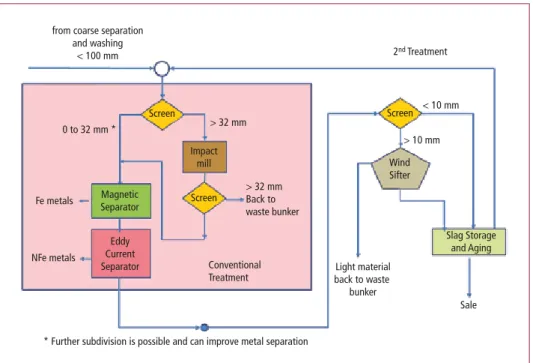
In Figure 2, the process steps of conventional and improved slag treatment are shown.
Waste Incineration
Figure 2: Conventional and improved slag treatment
Source: Maghon, T.: Potential of Resource Recovery out of Slag – Dry or wet slag extraction. Steinmüller Babcock Environment, European Conference on Energy and Environmental Technology 2013
2.1. Slag/bottom ash washing
First step of treatment is a slag washing which can take place within the wet deslagging equipment (ram type or apron conveyor) [7]. Instead of just adding water to make up losses due to evaporation, additional water will be added to reduce the contained soluble salts (SO42- and Cl-) and also to reduce the freight of fine particles which will be sent back to the waste bunker. The reuse within road construction or building industry in general is, amongst other quality characteristics, determined by the contamination of the mineral product with soluble salts and the leaching behavior of the slag. Thus the reduction will directly improve the quality and allow more flexibility for reuse and an increased market for such materials.
This system is implemented in two incineration plants in the city of Hamburg, MVR and MVB. The environmental permit of these facilities required stricter leachate limits compared to those valid for other plants. Therefore this simple solution was implemen- ted and is successfully in operation.
Alternatively, the washing may also take place in a separate step, either after coarse scrap metal separation or even after aging of the slag. This requires additional machinery and costs within the process chain of the slag treatment, but it can, on the other hand, improve the leaching behavior even further.
from coarse separation and washing
< 100 mm 2nd Treatment
< 10 mm
> 10 mm Screen
Sale Slag Storage
and Aging Light material
back to waste bunker
Wind Sifter Screen
Screen
> 32 mm
> 32 mm Back to waste bunker
Conventional Treatment 0 to 32 mm *
* Further subdivision is possible and can improve metal separation Fe metals
NFe metals
Magnetic Separator
Eddy Current Separator
Impact mill
Waste Incineration
2.2. Conventional screening
After the deslagging equipment, the conventional slag treatment follows with separation into two or more fractions – in the example in Figure 2: 0 to 32 mm and > 32 mm. From the small fraction, the Fe and Non-Fe metals will be separated by magnetic and eddy current separators. The larger fraction is treated by an impact mill in order to further reduce the grain size, and then another screen determines whether it is sent back to the waste bunker or treated with the finer fraction.
2.3. Optimized recycling
An improved slag treatment would then include another screening process with separation of the small fraction (< 10 mm and > 10 mm). The bigger fraction (> 10 mm) will include a considerable amount of light weight material such as plastics, which can be separated in a wind sifter and send back to the incineration, Figure 2.
Furthermore the subdivision after the first screening step can be improved: If finer fractions of the slag are being prepared by different screens – for example 0 to 4 mm, 4 to 10 mm, 10 to 20 mm and 20 to 32 mm, – with corresponding magnetic and eddy current sepa- rators for each fraction, this will improve the metal separation.
With the different fractions clearly divided, it will also be possible to prepare a slag aggregate in accordance with any byer’s requirements for the intended use, and thereby possibly increasing the market price for the slag.
As a further possibility to improve recycling rates, a glass separation is possible by optical methods. The separated glass fraction can then be returned into the recovered substance cycle with other collected waste glass.
3. Boiler and filter ash treatment
As mentioned earlier, the formation of PCDD/PCDF within a temperature window of 200 °C to 400 °C and especially in the presence of metallic catalysts is a particular problem when considering reuse or even storage of ashes generated from the flue gas cleaning process.
3.1. Boiler ash separation
As a first, quite simple approach to reduce the amount of hazardous ash, the separation of as much boiler ash as possible at higher flue gas temperature should be aimed at. There are several plants in operation with so called dust traps at the transition between the different boiler passes (2nd/3rd and 3rd/4th). These dust traps will separate especially bigger and heavier particles from the flue gas due to force of inertia. The dust can then either be treated with the bottom ash, or can be screened and treated separately with further Fe and Non-Fe metal separation.
3.2. Filter ash treatment
The remaining fly ash which is collected by the filter equipment contains a considerable amount of metals which are so far not being recovered. There are processes available to
Waste Incineration
separate different metal compounds from the ash, and these metals can then be recovered as a mixture or may also be separated one by one with additional processes.
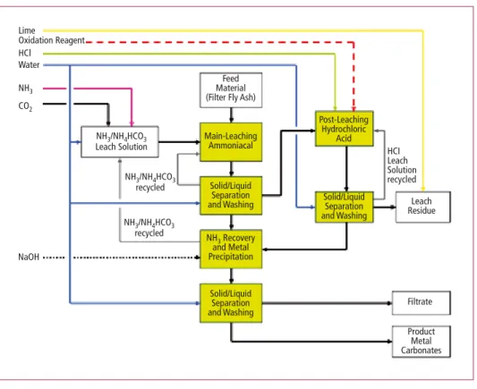
The proposed treatment system includes the following main steps:
• Leaching in two steps to dissolve metals. Two different steps are necessary to dissolve all the metals contained in the ash, as they do show different behavior in the leach solutions .
• Separation of the dissolved metals by forcing the formation of metal carbonates (solid) and corresponding liquid/solid separation
As one can see from Figure 3, there are 3 different outlet streams produced by the process:
• Solid leach residue, consisting of the mineral fraction of the filter ash. The leach resi- due is proposed to be pelletized and returned to the incineration process. It shall be incorporated into the slag/bottom ash.
• Filtrate containing dissolved calcium-, potassium- and sodium chloride. This filtrate has a similar composition as sea water and, in case of a plant in an archipelagic state, disposal in the ocean is an option.
• Metal carbonates (product) for selling on the marked and re-use for new products.
LimeOxidation Reagent HCl
Water NH3 CO2
NaOH
NH3/NH4HCO3 Leach Solution
NH3/NH4HCO3 recycled
NH3/NH4HCO3 recycled
Filtrate
Product Metal Carbonates
Leach Residue HCILeach Solution recycled Post-Leaching
Hydrochloric Acid
Solid/Liquid Separation and Washing Main-Leaching
Ammoniacal
Solid/Liquid Separation and Washing
Solid/Liquid Separation and Washing NH3 Recovery and Metal Precipitation
MaterialFeed (Filter Fly Ash)
Figure 3: Block diagram of ash treatment plant
Source: Pöyry Deutschland GmbH: Environmental impact study report for SDE waste incineration plant, 2013
Waste Incineration
The aforementioned process has been tested on laboratory scale. In addition similar leaching processes have been implemented in industrial scale as well, showing that the treatment is possible. The motivation for implementation of such a process can vary:
• Improvement of the recovery rate of metals,
• Reduction of the residue fraction to be deposited,
• Changing the composition of the filter ash, to fulfill any local legislative require- ments for further use or safe deposition of the ash.
4. HCl and gypsum generation
The proposed gas cleaning system which allows for optimized recycling rates includes a wet scrubbing process for precipitation of HCl and SOx emissions in two steps. The process so far just included a fabric filter to remove fly ash from the boiler and remo- val of Hg/Dioxins/Furans by injection of Activated Carbon, or equivalent products, upstream the filter.
4.1. HCl scrubber and HCl recovery
The first scrubber produces a raw acid with approximately 10 to 12 percent of HCl which is contaminated by some additional components which hinder direct marke- ting as a product. With the installation of an HCl rectification plant, the production of a marketable acid with 20 percent or 30 percent HCl is possible, depending which concentration is requested by the possible buyer.
The HCl-Rectification unit consists of the following process steps:
• Stripping of bromine and iodine with the addition of sodiumhyperchloride and absorption of these halogens with the addition of soda lye and sodiumthiosulfate.
• Evaporation of crude acid and separation of hydrogen fluoride (HF) by the addition of aluminumchloride.
• HCl distillation and concentration to the required strength of the hydrochloric acid.
Activated carbon filter to retain remaining impurities.
The residues produced in this hydrochloric acid rectification process are mainly salts of the halogens Br, J, F that are neutralized and recovered as a 20 percent brine.
4.2. SO
2scrubber and gypsum recovery
In the 2nd scrubber, working on a neutral pH value, the SOx contained in the flue gas is precipitated by the addition of hydrated lime. The overall chemical reaction can be summarized according to the following equation:
2 SO2(g) + 2 H2O(l) + 2 Ca(OH)2(s) + O2(g) → 2 CaSO4 • 2 H2O (s) + 2 H2O
Waste Incineration
The gypsum slurry has to be desiccated by a centrifuge and can then be processed for use in the construction industry. Very important for this further use is the strict abatement of Hg within the filter equipment upstream of the wet scrubbers. In this regard, the gypsum produced in waste incineration plants can be compared to natural gypsum, as fabric filters, which are usually used in waste incineration plants, have an unbeatable deposition rate of solids. This is even an advantage compared to gypsum from Coal fired power plants, equipped with electrostatic precipitators.
The combined process of HCl and SO2 scrubbers, in combination with recovery of HCl and gypsum is well proven and installations are in operation, for example in the waste incineration plants in Böblingen and MVR/MVB Hamburg. Apart from the idea of improved recycling, it has the advantage that there are no remaining solid residues. Compared to a dry or semi dry flue gas treatment system based on lime or sodiumbicarbonate this is a great benefit: These solid residues would require a secured hazardous waste disposal site, in order to avoid leaching of the Chlorides and Sulfates.
4.3. Recovery rates for Cl and S
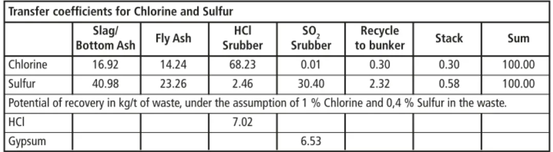
From the commercial point of view it is of course important to identify the possible recovery rate of Chlorine und Sulfur if the scrubbing process is installed as described above. The content of Chlorine in the waste input can be estimated with 0,6 percent to 1,4 percent, and the Sulfate content can be estimated to be 0,3 percent to 0,5 per- cent. The transfer coefficients of Cl and S into the various process streams are given in Table 3 – exemplary figures from the waste incineration plant RMVA Köln.
Table 3: Transfer coefficients for chlorine and sulfur into different output streams and recovery potential
Transfer coefficients for Chlorine and Sulfur Slag/
Fly Ash HCl SO2 Recycle
Stack Sum
Bottom Ash Srubber Srubber to bunker
Chlorine 16.92 14.24 68.23 0.01 0.30 0.30 100.00
Sulfur 40.98 23.26 2.46 30.40 2.32 0.58 100.00
Potential of recovery in kg/t of waste, under the assumption of 1 % Chlorine and 0,4 % Sulfur in the waste.
HCl 7.02
Gypsum 6.53
Source: L.C. Steinmüller GmbH: Transfer coefficients for hazardous substances into various output streams of the RMVA Köln, 1995
The potential for a plant with a waste throughput of 200,000 t per year can be roughly estimated to 1,400 t per year of HCl and 1,300 t per year of Gypsum.
5. Summary
The possibilities to improve recycling rates by using proven and new technologies in combination with waste incineration are given. Instead of treating waste incineration as being contradictory to recycling, it should be considered as one route to reach higher recycling rates.
Waste Incineration
Pointing the view, for example, on plastics, which are to a great extent divided from the waste stream before the waste is sent to an incineration plant: The plastic content which is finally burned in waste incineration plants is usually an undefined mixture which is just difficult to recycle and sell on the market. So it is reasonable to gain the chemical energy contained in these materials and then even recover the chloride content as HCl acid for other usages.
When it comes to metal recovery there is still a way to go. There have been numerous approaches in the past showing different possibilities to enhance the recovery of metals from the slag or the fly ash. Main incentive for these activities are ever increasing metal prices especially since the year 2000. The metal prices have, on the other hand, shown great fluctuations due to the financial crisis of 2009 and staggering economies. This uncertainty may hinder many operators of waste incineration plants and slag treatment specialists to invest in new technology and improve the recovery of metals from slag and from fly ash. But it is most likely that at some point the prices for metals will be high enough to justify higher effort and investments, and to implement additional or new treatment steps within the process chain of slag and ash treatment.
Finally the improvement of the slag quality can be used to optimize the recycling rate of waste incineration. A higher quality/less contaminated slag may open up new ap- plications for slag usage in the future or in new markets where such materials are in general scarce and much needed.
6. References
[1] Dehoust, G.; Gebhard, P.; Gärtner, S.: Der Beitrag der thermischen Abfallbehandlung zu Klimaschutz, Luftreinhaltung und Ressourcenschonung. Institut für angewandte Ökologie, Darmstadt, 2002
[2] Kost, T.: Brennstofftechnische Charakterisierung von Abfällen. In: Schriftenreihe des Instituts für Abfallwirtschaft und Altlasten, Band 16. Dresden, 2001
[3] L.C. Steinmüller GmbH: Transfer coefficients for hazardous substances into various output streams of the RMVA Köln, 1995
[4] Löschau, M.: Input-Output-Analyse als Methode der stofflichen Bilanzierung komplexer Ent- sorgungssysteme. Technische Universität Berlin, 2006
[5] Maghon, T.: Potential of Resource Recovery out of Slag – Dry or wet slag extraction. Steinmüller Babcock Environment, European Conference on Energy and Environmental Technology 2013 [6] Pöyry Deutschland GmbH: Environmental impact study report for SDE waste incineration plant,
2013
[7] Schäfers, W.; Schumacher, W.; Zwahr, H.: Die Müllverwertungsanlage Rugenberger Damm in Hamburg – Die logischer Weiterentwicklung eines bewährten Konzeptes, VGB Power Tech 77 (1997), Heft 9
Bibliografische Information der Deutschen Nationalbibliothek Die Deutsche Nationalbibliothek verzeichnet diese Publikation in der Deutschen Nationalbibliografie; detaillierte bibliografische Daten sind im Internet über http://dnb.dnb.de abrufbar
Thomé-Kozmiensky, K. J.; Thiel, S. (Eds.): Waste Management, Volume 6 – Waste-to-Energy –
ISBN 978-3-944310-29-9 TK Verlag Karl Thomé-Kozmiensky
Copyright: Professor Dr.-Ing. habil. Dr. h. c. Karl J. Thomé-Kozmiensky All rights reserved
Publisher: TK Verlag Karl Thomé-Kozmiensky • Neuruppin 2016
Editorial office: Professor Dr.-Ing. habil. Dr. h. c. Karl J. Thomé-Kozmiensky,
Dr.-Ing. Stephanie Thiel, M. Sc. Elisabeth Thomé-Kozmiensky, Janin Burbott-Seidel und Claudia Naumann-Deppe
Layout: Sandra Peters, Anne Kuhlo, Janin Burbott-Seidel, Claudia Naumann-Deppe, Ginette Teske, Gabi Spiegel und Cordula Müller
Printing: Universal Medien GmbH, Munich
This work is protected by copyright. The rights founded by this, particularly those of translation, reprinting, lecturing, extraction of illustrations and tables, broadcasting, micro- filming or reproduction by other means and storing in a retrieval system, remain reserved, even for exploitation only of excerpts. Reproduction of this work or of part of this work, also in individual cases, is only permissible within the limits of the legal provisions of the copyright law of the Federal Republic of Germany from 9 September 1965 in the currently valid revision. There is a fundamental duty to pay for this. Infringements are subject to the penal provisions of the copyright law.
The repeating of commonly used names, trade names, goods descriptions etc. in this work does not permit, even without specific mention, the assumption that such names are to be considered free under the terms of the law concerning goods descriptions and trade mark protection and can thus be used by anyone.
Should reference be made in this work, directly or indirectly, to laws, regulations or guide- lines, e.g. DIN, VDI, VDE, VGB, or these are quoted from, then the publisher cannot ac- cept any guarantee for correctness, completeness or currency. It is recommended to refer to the complete regulations or guidelines in their currently valid versions if required for ones own work.