(ΩDated: June 2, 2015)
We perform a comparative study of the spin relaxation by spin-orbit coupling induced from adatoms (hydrogen and fluorine) in graphene. Two methods are applied, giving consistent results:
a full quantum transport simulation of a graphene nanoribbon, and a T-matrix calculation using Green’s functions for a single adatom in graphene. For hydrogenated graphene the dominant spin- orbit term for spin relaxation is PIA, the hitherto neglected interaction due to pseudospin inversion asymmetry. In contrast, in fluorinated graphene PIA and Rashba couplings destructively interfere, reducing the total spin relaxation rate. In this case we also predict a strong deviation from the expected 2:1 spin relaxation anisotropy for out- and in-plane spin orientations. Our findings should be useful to benchmark spin relaxation and weak localization experiments of functionalized graphene.
PACS numbers: 71.70.Ej, 72.25.Rb, 72.80.Vp, 73.23.-b
Keywords: resonant scattering, spin-relaxation, spin-orbit coupling, hydrogenated and fluorinated graphene
The spin properties of graphene derive, to a large ex- tent, from what we combine it with [1]. In particular, functionalizing graphene with adatoms and molecules, which can induce giant spin-orbit couplings, is a promis- ing path towards practical graphene-based devices for spintronics [2, 3]. Indeed, adatoms such as hydrogen, fluorine, or copper, have been shown theoretically [4–
6] and experimentally, by measuring the spin Hall effect [7, 8], to enhance the spin-orbit coupling of graphene, from about 10µeV in pristine graphene [9], to about 1- 10 meV, enough to cause sizable spin precession.
On the other hand, graphene’s spin relaxation rate is also plagued by the (unintentional) extrinsic sources.
The measured spin lifetimes in graphene are on the or- ders of 0.1−1 ns [10–20], which are consistent with the presence of magnetic moments on adatoms or organic molecules [21] chemisorbed on graphene, in both mono [22] and bilayer [23] forms. As little as 1 ppm of such mo- ments can induce ultrafast spin relaxation seen in spin in- jection experiments. The reason is that adatoms such as hydrogen, or organic molecules, not only induce magnetic moments, but also act as resonant scatterers [22,24,25].
Spin-orbit coupling (SOC) in graphene can still play an important role in three regimes: (i) First, in the ultra- clean high mobility limit in which SOC can induce a spin precession rate which is faster than the momentum relax- ation rate. In such a case the averaging over the electron ensemble in the momentum space can lead to an ultra- fast spin dephasing [2]. (ii) Second, in graphene covered with heavy adatoms (Au, W, Tl) which typically sit on the hexagon centers and which induce strong SOC. The case of Au adatoms was recently investigated theoreti- cally [26], discovering a new spin-pseudospin entangle- ment mechanism of spin relaxation specific to graphene.
The third regime, (iii), which is the subject of this paper, is graphene functionalized with light adatoms (H, F, Cu) or molecules (CH3) which prefer to sit at top (sometimes bridge) positions. While the induced SOC is much less
than in (ii), such adatoms scatter Dirac electrons reso- nantly, strongly enhancing the spin-flip scattering and, with a sufficient coverage (0.01 - 1%, depending on the adatom), can overcome the dominance of local magnetic moments in spin relaxation and lead to sub 100 ps spin lifetimes.
We perform numerical and analytical investigations of the spin relaxation rates in graphene due to SOC of adatoms. We choose hydrogen and fluorine, for which realistic scattering potentials have been introduced from first-principles calculations [5, 6]. Hydrogen should be taken as an example of a class of adatoms with reso- nances close to the Dirac point, not literally as a hydro- gen adatom, since hydrogen also introduces local mag- netic moments [27] which would overshadow the effects of SOC in spin relaxation. Fluorine, on the other hand, can be taken as a representative case for adatoms with reso- nances away the Dirac point, since first-principles studies and experiments [28] are inconclusive about its induced magnetic moment. What we find is that the SOC reso- nantly enhances the spin relaxation rate. This is similar to the resonant enhancement of the spin Hall effect due to adatoms, as recently predicted [29, 30]. Next, we show that the hitherto neglected PIA (pseudospin inversion asymmetry) spin-orbit interaction is dominant in spin relaxation, relative to Rashba and intrinsic couplings, al- though in fluorinated graphene PIA and Rashba destruc- tively interfere. Finally, we find that while for hydrogen- like adatoms the universal spin relaxation anisotropy of 2:1, for out- and in-plane spin relaxation, strictly holds, the anisotropy can be significantly weaker for fluorine-like adatoms in which the intrinsic SOC becomes important at off-resonance energies.
We solve the spin relaxation problem due to adatom- induced SOC by two complementary techniques, a fully numerical quantum transport simulation for a finite graphene stripe, and an analytical calculation of the T- matrix for the given adatom. We bridge the two using
arXiv:1506.00040v1 [cond-mat.mes-hall] 29 May 2015
DOS [a.u.]
0.4 0.2 0.0 0.2 0.4
E [eV]
DOS [a.u.]
(a)
(b)
(e)
(f) (c)
(d)
FIG. 1. (Color online) Adatoms on graphene. Panels (a) and (b) show the orbital and spin-orbit tight-binding hoppings, respectively, as described in text. The calculated DOS is in (c) for hydrogenated and in (d) for fluorinated graphene. Dotted lines are for a 20×20 tight-binding supercell calculation (impurity concentration per carbon 0.125%), while solid lines are obtained from the T-matrix single-adatom scattering formalism [6]. Pristine graphene linear DOS is also given. Panels (e) and (f) compare the electron densities around a hydrogen adatom at resonant (E = 7 meV) and off-resonant energies (E=−500 meV).
the scattering formalism for graphene, showing that they give consistent results. This by itself should be useful for other studies based on Landauer transport, for convert- ing the transmission and reflection probabilities to the scattering rates directly. We believe that our investiga- tions of the spin relaxation due to SOC will serve as a benchmark study for experimental investigations of the spin relaxation of functionalized graphene.
We focus on graphene with a dilute (such that scat- tering interferences can be ignored) coverage of adatoms that bond covalently to host’s carbons at top positions.
Although our findings are general, we specifically con- sider hydrogen and fluorine adatoms for which we have realistic Hamiltonians H= Hgr+V, with Hgr describ- ing graphene (the usual nearest neighbor hopping Hamil- tonian) and V describing the adatom potential, both orbital and spin-orbital. Parameters entering V come from fits to first-principles data [5, 6]. These Hamil- tonians are illustrated in Fig. 1 and reproduced in de- tail in Suppl. Material (SM) [31]. The orbital part, in Fig.1(a), comprises the on-site energyε and hoppingω between the adatom and the carbon atom underneath.
The spin-orbit part, in Fig. 1(b), has the intrinsic (I) spin-preserving intra-sublattice couplings ΛAI and ΛBI, the Rashba (R) inter-sublattice spin-flip hopping ΛR, and the pseudospin-inversion asymmetry (PIA) terms ΛAPIA and ΛBPIA which couple the same sublattice with a spin flip [5].
Both hydrogen and fluorine are resonant adatoms, albeit with qualitatively different features. The nar- row hydrogen resonance [22, 24] is located close to the charge neutrality point at Eres ≈ 7 meV with the full width at half maximum (FWHM) of 5 meV; see the density of states (DOS) in Fig. 1(c). The broad fluo-
rine resonance [6] is centered at Eres ≈ −260 meV with FWHM≈300 meV, see Figs.1(d). To illustrate the res- onant behavior we compare in Figs.1(e) and (f) electron densities around a hydrogen adatom at resonant and off- resonant energies. While off-resonance the states are de- localized, they are confined to the adatom site at reso- nance. More details about local DOS analyzes are in SM [31].
We investigate spin transport and spin relaxation of Dirac electrons in the presence of adatoms by two com- plementary approaches: (i) numerical calculation of a real-space Green’s function for a graphene nanoribbon [32, 33] of width W, with periodic boundary condi- tions along a transverse direction, and (ii) an analytical non-perturbative calculation of spin scattering relaxation rates. Both techniques are well established and we sum- marize their application to our problem in SM [31]. In (i) we obtain the spin-flip probability
Γs(E) = X
σ∈{±1}
X
i,j
|ti,j;σ,−σ|2+|ri,j;σ,−σ|2 (1)
which is a function of the electron energy E. In the above formulatandrare the transmission and reflection amplitudes between left-right propagating modesiandj of opposite spinsσ. In approach (ii) we get directly the spin relaxation rate 1/τs(E) from the T-matrix,
Tm,σ|n,−σ(E) = m, σ
V
1−G(E)V−1 n,−σ
, (2) wherem and nlabel atomic positions, and G(E) is the energy dependent Green’s function of graphene which is known analytically close to the Dirac point [34–36], see also [31], so we can obtain T(E) fully non-perturbatively and study resonances.
[1 /s ] [1 /s ]
-0.4 -0.2 0 0.2 0.4
[eV]
-0.4 -0.2 0 0.2 0.4
[eV]
-0.4 -0.2 0 0.2 0.4
[eV]
-0.4 -0.2 0 0.2 0.4
[eV]
10
410
610
810
010
210
410
610
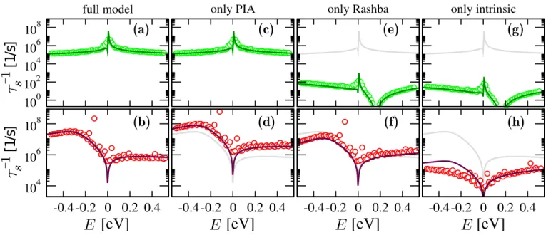
FIG. 2. (Color online) Calculated spin-relaxation rates as functions of the Fermi level for hydrogenated (upper panels) and fluorinated (lower) graphene, with impurity concentrationη = 53 ppm/carbon. Symbols represent numerical Landauer-type calculations and solid lines come from analytical T-matrix analysis. Panels (a) and (b) show total spin-relaxation rates implementing all SOC terms. Other columns show the spin-relaxation rates due to one SOC term only—PIA [panels (c), (d)], Rashba [panels (e), (f)], and intrinsic [panels (g) and (h)] couplings; for comparison the total rates are reproduced as grey lines.
The PIA coupling generally dominates over the Rashba and intrinsic ones, most pronounced for hydrogenated graphene.
To connect the two approaches we need a relation between Γs(E) and 1/τs(E). To this end we solve the Lippmann-Schwinger equation |Ψ+Ei = |inEi + G(E)T(E)|inEi. Here |inEi = |q, τ, σi is the incoming unperturbed low-energy Bloch state (normalized to the graphene unit cell), labeled with valley index τ = ±1, momentumq(measured from the Dirac pointτK), spin σ =±1, and positive energy E =~vF|q| >0; negative energies can be treated analogously. Fixing an atomic site m with a position vector Rthat lies far away from the impurity region we get for the amplitude hm|outEi of the outgoing wave|outEi=G(E)T(E)|inEi:
hm|outEi ' ei|R||q|
p|R|
X
τ0 ∈{±τ}
σ0 ∈{±σ}
eiτ0K·Rfστ00στ(q0,q, E), (3)
whereq0 =|q||R|R ,K=4π3a(1,0) (a= 2.46 ˚A is the lattice constant), and the partial amplitudes
fστ00στ(q0,q, E) =− s
√iEa 12πt3
q0, τ0, σ0 T(E)
q, τ, σ . (4) This matrix element can be obtained analytically—in the local atomic basis the T-matrix is a finite 20×20-matrix, see SM [31]. Terms entering the sum in Eq. (3) with τ0 =τ (τ0 = −τ) contribute to the intra (inter) valley scattering, while those withσ0=σ(σ0=−σ) contribute to the spin conserving (spin flip) scattering. The total spin-flip scattering cross-section for the energy E and
valley τ averaged over the incident directions then be- comes
σsτ(E) = X
τ0 ∈{±τ}
σ∈{±1}
2π
Z
0
dϕq 2π
2π
Z
0
dϕq0
f−σστ0τ (q0,q, E)
2, (5)
where ϕq(0) is the polar angle of q(0) with respect to x- axis. For a nanoribbon with a widthW σsτ the spin- flip scattering probability for the left-right charge-carriers transport equals Γs(E) = (1/2W)P
τ∈{±}στs(E). Form- ing the rate equations in terms of the T-matrix and sum- ming over all processes at given energyEwe get for the spin-relaxation rateτs−1(E) at zero temperature
τs−1(E) =2π
~ η t
πa X
τ∈{±}
στs(E) =4t
~ η W
a Γs(E). (6) Here η stands for the adatom concentration per carbon andt= 2.6 eV for the plane graphene hopping.
The main result of this paper is shown in Fig. 2.
The Landauer transport data are obtained from zig-zag nanoribbon of length L = 62a and width W = 130a, with a single adatom impurity. This corresponds to η = 53 ppm/carbon. The initial spin polarization is in the graphene plane. The agreement between the Lan- dauer (i) and the T-matrix (ii) approaches is remarkable, proving the validity of Eq. (6).
We first look at hydrogenated graphene, see Fig.2(a).
The spin relaxation rate is strongly enhanced at reso- nance, which is close to the Dirac point, following the
analogous resonance dependence as the DOS in Fig. 1.
At resonance the spin relaxation rate is an order of mag- nitude greater than off resonance. The shortest spin re- laxation time at resonance is about 100 ns. In the case of magnetic moments, the shortest spin relaxation time would be about 1 ps for this adatom concentration [22], reaching the momentum relaxation time. The spin-orbit coupling mechanism is much less effective here, since the spin-orbit energy is smaller than the resonance width.
Typical the electron spends less time on the adatom than what would be required for a spin precession by the adatom-induced SOC. For exchange coupling the sit- uation is the opposite: during the dwell on the adatom the spin can fully precess about the exchange field, so the spin flip and spin conserving scatterings are equally likely. Recently it was demonstrated using first-principles quantum transport calculations [37] that the exchange coupling due to hydrogen adatoms in graphene nanorib- bons can cause spin-flip conductance as large as the spin- conserving one, confirming the resonance model picture.
Which of the three spin-orbit coupling terms, PIA, Rashba, and intrinsic, contribute most to the spin re- laxation? We performed calculations with the individ- ual terms only and find that PIA only is responsible for the spin relaxation in hydrogenated graphene due to spin-orbit coupling. Remarkably, the contributions from Rashba and intrinsic couplings are smaller by several or- ders of magnitude. To explain this we analyzed the local DOS around the adatom site. At resonance, the electron density on carbon beneath the adatom gets strongly re- duced, see Fig.1(e). Having two carbon sites C1and C2
connected by SOC hopping Λ, the effective spin-flip prob- ability is directly proportional to|Λ|2ν(C1)ν(C2), where ν(C1) and ν(C2) stand for the local DOS at those car- bons. For the Rashba ΛRand intrinsic ΛAI SOC hoppings the affected carbon site is directly involved and hence we expect a weaker spin relaxation as compared with ΛBPIA that connects carbon atoms on the populated sublattice;
for hydrogen ΛBI and ΛAPIAvanish, see SM [31].
We now turn to fluorinated graphene. The spin-orbit terms induced by fluorine are greater by decade compared to hydrogen, so one expects the spin relaxation rate up to two decades faster. This is indeed what we find, as shown in Fig.2(b). However, the dependence of 1/τson energy looks very different from the hydrogen case. The rate has a broad peak at negative energies, vanishes at the Dirac point, and becomes rather flat at positive energies.
The broad feature at negative energies can be connected to the resonance seen in the DOS in Fig.1(d), implying resonance enhancement of the spin relaxation. Close to the Dirac point, the DOS vanishes and the scattering theory predicts a vanishing scattering probability as well (unless the resonance is close to that, as for hydrogen adatoms); this is why the spin relaxation rate has a dip there.
Resolving different spin-orbit terms uncovers a surpris-
1.6 1.7 1.8 1.9 2
anisotropy ratio
-0.4 -0.2 0 0.2 0.4
[eV]
1.6 1.7 1.8 1.9 2
anisotropy ratio
fluorinated graphene full model only PIA only Rashba hydrogenated graphene
full model only PIA only Rashba
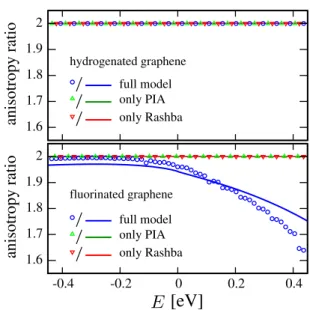
FIG. 3. (Color online) Calculated spin relaxation anisotropy as the defined ratio of 1/τsfor electron spins out- and in-plane, for hydrogenated (top panel) and fluorinated (bottom panel) graphene. For the hydrogenated graphene the anisotropy ra- tio is 2 (all lines are on top of each other), as expected for spin-orbit fields; intrinsic coupling plays no role. For the fluo- rinated graphene the anisotropy drops well below 2 at positive energies, as here also the intrinsic coupling becomes impor- tant. Symbols represent numerical calculation and solid lines come from analytical model.
ing effect ofdestructive interference between the Rashba and PIA couplings. Indeed, considered individually, the spin relaxation rate due to the PIA interaction, as in hy- drogenated graphene, is greater than the rate due to all interactions together, see Fig.2. The intrinsic term plays a minor role only, becoming important only at high pos- itive energies. The destructive interference between PIA and Rashba SOC in the case of fluorinated graphene re- duces the effective value of PIA, and with it the spin relaxation rate. We identify this destructive path as the successive Rashba (spin-flip nearest neighbor) and orbital t (spin-conserving nearest neighbor) hopping, which ef- fectively leads to a next-nearest-neighbor spin-flip, just like PIA, but with the opposite sign. Details are found in SM [31].
Finally, we consider spin relaxation anisotropy, which is an experimentally important fingerprint of the SOC mechanism. Indeed, spin-orbit fields (PIA and Rashba) lie in the graphene plane. An electron spin which points out of plane can be flipped by two independent compo- nents of a given spin-orbit field, while an electron spin lying in the plane can be flipped by only one component (perpendicular to that spin). This gives the expected 2:1 ratio of the spin relaxation for out- and in-plane spins.
This is also expected for graphene, if its spin relaxation is due to SOC. For the hydrogenated graphene case our calculations show no deviation from this expectation, see
the relaxation is due to the spin-orbit fields only. In contrast, our calculations for fluorinated graphene show marked deviations from the 2:1 expectation at positive energies. At those energies the intrinsic SOC becomes also important, deforming the spin-flip picture due to spin-orbit fields only.
In conclusion, we showed that spin-orbit induced spin- relaxation in graphene functionalized with adatoms (we gave examples of hydrogen and fluorine) can exhibit a giant enhancement at resonances and, for a sufficient adatom concentration, overcome the magnetic-moment limited spin relaxation. For both hydrogen and fluorine the PIA interaction gives the dominant contribution, al- though in fluorinated graphene it interferes destructively with the Rashba coupling. Intrinsic SOC is inhibited in the spin relaxation processes, but can become important off resonance and even strongly modify the spin relax- ation anisotropy, providing an important signature that could be tested experimentally.
This work was supported by DFG SFB 689, GRK 1570, Hans-B¨ockler-Stiftung, and by the EU Sev- enth Framework Programme under Grant Agree- ment No. 604391 Graphene Flagship.
[1] W. Han, R. K. Kawakami, M. Gmitra, and J. Fabian, Nat. Nanotechnol.9, 794 (2014).
[2] I. ˇZuti´c, J. Fabian, and S. Das Sarma, Rev. Mod. Phys.
76, 323 (2004).
[3] J. Fabian, A. Matos-Abiague, C. Ertler, P. Stano, and I. ˇZuti´c, Acta Phys. Slovaca57, 565 (2007).
[4] A. H. Castro Neto and F. Guinea, Phys. Rev. Lett.103, 026804 (2009).
[5] M. Gmitra, D. Kochan, and J. Fabian, Phys. Rev. Lett.
110, 246602 (2013).
[6] S. Irmer, T. Frank, S. Putz, M. Gmitra, D. Kochan, and J. Fabian, Phys. Rev. B91, 115141 (2015).
[7] J. Balakrishnan, G. K. W. Koon, M. Jaiswal, A. H. Cas- tro Neto, and B. ¨Ozyilmaz, Nature Physics9, 284 (2013).
[8] J. Balakrishnan, G. Koon, A. Avsar, Y. Ho, J. Lee, M. Jaiswal, S. Baeck, J. Ahn, A. Ferreira, M. Cazalilla, A. C. Neto, and B. ¨Ozyilmaz, Nature Communications 5, 4748 (2014).
[9] M. Gmitra, S. Konschuh, C. Ertler, C. Ambrosch-Draxl, and J. Fabian, Phys. Rev. B80, 235431 (2009).
[10] N. Tombros, C. Jozsa, M. Popinciuc, H. T. Jonkman, and B. J. van Wees, Nature448, 571 (2007).
[11] N. Tombros, S. Tanabe, A. Veligura, C. Jozsa, M. Popin- ciuc, H. T. Jonkman, and B. J. van Wees, Phys. Rev.
Lett.101, 046601 (2008).
[12] K. Pi, W. Han, K. M. McCreary, A. G. Swartz, Y. Li, and R. K. Kawakami, Phys. Rev. Lett. 104, 187201
M. Jaiswal, J. Samm, S. R. Ali, A. Pachoud, M. Zeng, M. Popinciuc, G. G¨untherodt, B. Beschoten, and B. ¨Ozyilmaz, Phys. Rev. Lett.107, 047206 (2011).
[14] W. Han and R. K. Kawakami, Phys. Rev. Lett. 107, 047207 (2011).
[15] A. Avsar, T.-Y. Yang, S. Bae, J. Balakrishnan, F. Volmer, M. Jaiswal, Z. Yi, S. R. Ali, G. G¨untherodt, B. H. Hong, B. Beschoten, and B. ¨Ozyilmaz, Nano Let- ters11, 2363 (2011).
[16] S. Jo, D.-K. Ki, D. Jeong, H.-J. Lee, and S. Kettemann, Phys. Rev. B84, 075453 (2011).
[17] R. G. Mani, J. Hankinson, C. Berger, and W. A. de Heer, Nature Commun.3, 996 (2012).
[18] M. H. D. Guimar˜aes, P. J. Zomer, J. Ingla-Ayn´es, J. C.
Brant, N. Tombros, and B. J. van Wees, Phys. Rev. Lett.
113, 086602 (2014).
[19] M. Dr¨ogeler, F. Volmer, M. Wolter, B. Terr´es, K. Watan- abe, T. Taniguchi, G. G¨untherodt, C. Stampfer, and B. Beschoten, Nano Letters14, 6050 (2014).
[20] M. Venkata Kamalakar, C. Groenveld, A. Dankert, and S. P. Dash, Nature Commun.6, 6766 (2015).
[21] E. J. G. Santos, A. Ayuela, and D. S´anchez-Portal, New Journal of Physics14, 043022 (2012).
[22] D. Kochan, M. Gmitra, and J. Fabian, Phys. Rev. Lett.
112, 116602 (2014).
[23] D. Kochan, S. Irmer, M. Gmitra, and J. Fabian, arXiv:1504.03898.
[24] T. O. Wehling, S. Yuan, A. I. Lichtenstein, A. K. Geim, and M. I. Katsnelson, Phys. Rev. Lett. 105, 056802 (2010).
[25] J. Bundesmann,Spin-dependent Transport in Graphene Nanostructures, Ph.D. thesis, Universit¨at Regensburg (2014).
[26] D. V. Tuan, F. Ortmann, D. Soriano, S. O. Valenzuela, and S. Roche, Nat. Phys.10, 857 (2014).
[27] O. V. Yazyev, Phys. Rev. Lett.101, 037203 (2008).
[28] X. Hong, K. Zou, B. Wang, S.-H. Cheng, and J. Zhu, Phys. Rev. Lett.108, 226602 (2012).
[29] A. Ferreira, T. G. Rappoport, M. A. Cazalilla, and A. Castro Neto, Phys. Rev. Lett.112, 066601 (2014).
[30] A. Pachoud, A. Ferreira, B. ¨Ozyilmaz, and A. H. Cas- tro Neto, Phys. Rev. B90, 035444 (2014).
[31] Supplemental Material; send on request by D.K.
[32] M.-H. Liu and K. Richter, Phys. Rev. B 86, 115455 (2012).
[33] M. Wimmer, Quantum transport in nanostructures:
From computational concepts to spintronics in graphene and magnetic tunnel junctions, Ph.D. thesis, Universit¨at Regensburg (2009).
[34] Z. F. Wang, R. Xiang, Q. W. Shi, J. Yang, X. Wang, J. G.
Hou, and J. Chen, Phys. Rev. B74, 125417 (2006).
[35] M. Sherafati and S. Satpathy, Phys. Rev. B83, 165425 (2011).
[36] F. Ducastelle, Phys. Rev. B88, 075413 (2013).
[37] J. Wilhelm, M. Walz, and F. Evers, arXiv:1504.06720.
![arXiv:1507.00928v1 [cond-mat.mes-hall] 3 Jul 2015](data:image/gif;base64,R0lGODlhAQABAIAAAP///wAAACH5BAEAAAAALAAAAAABAAEAAAICRAEAOw==)